1
Operator’s Manual
HV SERIES
Electric Motor - NG/LP fired
READ
THIS
MANUAL
This manual contains important information for the use and safe operation of
your RAMTEQ machine. FAILURE TO READ THIS MANUAL AND
FOLLOW ITS INSTRUCTIONS PRIOR TO OPERATING OR ATTEMPTING
ANY SERVICE OR MAINTENANCE PROCEDURE COULD RESULT IN
SERIOUS INJURY OR DEATH TO YOU OR OTHER PERSONS; ALSO
DAMAGE TO THE MACHINE OR TO OTHER PROPERTY.
®
RAMTEQ 14275
14275 northwest
northwest freeway
freeway
®
Houston,
Houston, TX
TX 77040
77040
phone:
phone: 713.983.6000
713.983.6000
fax:
fax: 713.983.6405
713.983.6405
300-00004-01
300-00004-01 7/06
8/05
Operator’s Manual
Page Table of Contents
Section 1
Operator’s Manual
Unpacking....................................................................2
Safety Guidelines........................................................3 Installation Instructions.............................................4
Operating Instructions...............................................5
Maintenance Instructions...........................................5
Section 2 Parts
and
Service Manual
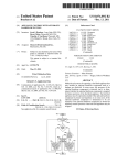
Parts Diagram.............................................................7
Parts List.....................................................................7
Hose, Wand, & Gun.....................................................11
Wiring Diagram............................................................12
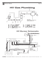
Gas Plumbing Diagram.................................................13
HV Burner Schematic..................................................13
Troubleshooting..........................................................14
Warranty................................................................15
Unpacking Instructions
INSPECTION
Carefully unpack your new RAMTEQ equipment by removing the banding
and cardboard box from pallet. Remove the pressure washer from the
pallet and check for any physical damages that may have occurred during
shipment. Check for all parts specified and shown below. Included Parts
• Pallet
• Packing Material
Outer Box
• HV Series Machine
• Operator’s Manual
• Wand / Trigger Gun
• Nozzles 0º 15º 25º 40º
• Hose 3/8” X 50’
• QC Hose Fittings
NOTICE
Information in this operator’s manual is subject to change without notice. RAMTEQ SHALL NOT BE LIABLE FOR TECHNICAL OR EDITORIAL ERRORS OR OMISSIONS CONTAINED HEREIN. This operator’s manual
contains information protected by copyright. No part of this operator’s manual may be photocopied or reproduced in any form without
prior written consent from RAMTEQ®.
© RAMTEQ®, 2005
All rights reserved. Printed in USA.
RAMTEQ 14275
®
northwest freeway
Houston, TX 77040
phone: 713.983.6000
fax: 713.983.6405
300-00004-01
7/06
Operator’s Manual
Page Safety Guidelines
�
WARNING
READ THIS FIRST! Failure to read and observe all
WARNING statements could result in severe bodily
injury or death, possible injury to other persons,
damage to machine or other property.
DO NOT operate this machine in areas where open flames are not permitted. DO NOT store or
use combustible materials on or near this machine. Use this equipment only in well ventilated
areas. Failure to follow this warning may cause carbon monoxide build up, fire or explosion, and
possible injury or death.
DO NOT operate this machinery unless the gas installation has been done by a competent
professional and the installation meets all federal, state, and local codes.
DO NOT operate this machine while under the influence of alcohol, drugs or while fatigued.
DO NOT direct discharge stream at yourself or others. Risk of injection or injury may occur.
Never put your hand or fingers over the spray tip. Do not try to stop or deflect leaks with your hand or body. Always face nozzle and wand to the ground when testing.
DO NOT operate this machine without wearing protective Eye Wear. Gloves, Hard Hat, Mask, Ear Plugs & Steel Toe Work Boots are also recommended, DO NOT wear loose clothing. Keep
your body and clothing clear of the engine and discharge stream when the machine is running.
DO NOT tie back or block trigger gun in OPEN position. Never leave the pressure washer
unattended once you have started it. If you leave, shut down machine completely.
DO NOT overreach or stand on an unstable support while operating this machine. Maintain
good footing and balance.
DO NOT permit this machine to run while unattended or for extended periods of time with
trigger gun closed. Damage to pump may occur.
DO NOT operate this machine in an unsafe manner or around unsupervised children. Keep all
other personnel clear while operating this machine. This product should only be operated by
trained personnel.
DO NOT alter original factory settings prior to operating this machine. Risk of injury to yourself or
other persons may occur.
DO NOT remove hoses, guns, nozzles or any components while this machine is still hot or while
it is running.
DO NOT attempt to service this machine before reading the service manual.
DO NOT use water with a temperature over 140 degrees Fahrenheit
DO NOT use any electrical outlet that is not properly grounded or does not comply with all
federal, state, and local laws and/or electrical codes
DO NOT operate this machine without knowing how to stop and bleed water pressures. Know all
controls before using this machine.
DO NOT spray caustic, acids or abrasive fluids through this machine.
DO NOT permit water to freeze inside this machine. Pump and plumbing damage may occur.
Use only recommended RAMTEQ parts when servicing this machine.
RAMTEQ will not be held liable for any unauthorized modifications made to this
machine. Any such action will void the warranty.
RAMTEQ 14275
®
northwest freeway
Houston, TX 77040
phone: 713.983.6000
fax: 713.983.6405
300-00004-01
7/06
Operator’s Manual
Page Installation Instructions
LOCATION & INSTALLATION GUIDELINES
Locate the machine on a solid and level surface so that engine and pump crankcase oil lubricate components properly.
Avoid areas where water can build up in the working area. Possible injury can occur caused by the surface becoming
slippery from water build up.
Locate the machine in a well-ventilated area and away from flammable materials or fumes. Be sure ventilation warnings
are observed. Keep pressure washer at least 18” away from flamable materials.
Locate the machine so the operator has easy access to the pressure washer and its controls. Locate the machine so that
it is protected from external damage.
Confer with local gas company, and with proper municipal officials regarding any specific code or regulations governing this installation. Installation must conform with all local codes prior to operation of machine.
A draft diverter hood must be installed and vented to the outside.
Check gas union located under burner ring prior to operation. Soap test gas pipe fittings for leaks once pressurized.
To prevent damage and excessive hose wear, locate the pressure washer so that the hose does not cross traffic areas
The gas line should be a separate supply direct from the meter to the burner. New pipe is recommended to be
used and located so that a minimum amount of work will be required in future servicing. The piping should be
so installed as to be durable, substantial and gas tight. It should be clear and free from cutting burrs and defects
in structure of threading. Cast iron fittings or aluminum tubing should not be used for the main gas circuit. Joint
compounds (pipe dope) should be used sparingly on male threads only and be approved for all gases.
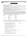
The following pipe sizes should be used between the meter and the machine:
Natural Gas
Distance from Meter Pipe Size
0 - 50’ 50’ - 100’ 100’ - 200’ 1-1/2” 1 PS
2” 1 PS
2-1/2” 1 PS
Liquid Propane Distance from Meter Pipe Size
0 - 50’ 50’ - 100’ 100’ - 200’ 1” 1 PS
1-1/2” 1 PS
1-3/4” 1 PS
Venting: A vented draft diverter hood should be used with all indoor installations. Poor draft will cause the
machine to soot and not operate efficiently. Positioning of the machine should be in such a manner so that the
stack is as straight as possible and have suffecient height to eliminate downdraft.
Natural Gas & LP Installation Checklist
Checked
Has gas supply been inspected by an authorized
contractor and meets all local codes? _____ Is machine protected from downdraft and excessive wind?
_____ Is machine shielded from moisture of water spray?
_____ Is voltage correct and circuit breaker adequate according
to specifications and serial plate notations?
_____ Is the machine electrically grounded?
_____ _____ _____ Have all flammable liquids or gases been removed
from location?
Is there adequate gas supply for BTU rating of the burner?
Is incoming gas supply pressure between 6” and 14” water column?
Has the proper gas regulator been installed with proper
pressure and volume?
Is machine properly vented allowing adequate air flow? Are the propane tanks large enough to prevent freezing? Have gas lines been checked for gas leaks?
RAMTEQ 14275
®
northwest freeway
Houston, TX 77040
_____ _____
_____
_____ _____ phone: 713.983.6000
fax: 713.983.6405
300-00004-01
7/06
Operator’s Manual
Page Operating Instructions
STARTING THE MACHINE
Following the steps below will insure successful operation:
Read this manual completely before attempting to start the machine.
Check that the Motor/Burner switches are in the "OFF" position
Check the pump oil level and fill with SAE 30w non-detergent oil if needed.
Connect water hose to pump (or float tank if equipped). Turn on water source.
Connect the power cord to a properly grounded power source.
Turn the manual gas valve to “ON” position. Adjust incoming gas to 12” wc minimum for LP unit, 5” wc minimum for NG
(maximum14”wc or 1/2psi). The correct operating manifold pressure for natural gas is 3.5” wc and 11” wc for propane.
Attach high pressure hose to base of spray gun.
Install water nozzle at the end of wand, making sure it is clear of any obstructions.
Turn pump switch to “ON”
Pull trigger on gun until a steady stream of water comes out the nozzle. This purges any air in the system.
Check for leaks in the system and cycle trigger gun to insure bypass is adjusted correctly. Repair any leaks and correct unloader adjustment if needed. Turn off machine before attempting any repairs.
Turn burner switch to "ON". Check for buner ignition.
Adjust thermostat to desired temperature appropriate to the task. Maximum temperature setting may not be needed.
Insert detergent siphoning tube into a DOT approved container and open the metering valve for detergent application.
WASHING TECHNIQUES
Washing from bottom up increases dwell time of soap and lessens vertical streaks.
Turn soap metering valve “OFF” to purge system of soap
Rinsing with cold water from top down will retard detergent reaction which will enhance the rinsing performance.
Wash at 30 to 60 degree angles to prevent splashback.
STOPPING THE MACHINE
Turn burner switch to “OFF”. Allow water to discharge for a few minutes while cooling down.
Turn pump switch to "OFF".
Disconnect water source.
Pull gun trigger to release water pressure from system.
Disconnect wand & gun assembly.
Wind up pressure hose on hose reel.
Maintenance Instructions
MAINTENANCE PRECAUTIONS
Do not permit acidic, caustic or abrasive fluids to be pumped through system.
Periodically clean detergent inlet screen. This will ensure proper flow of water to the pump.
High mineral content in water may adversely affect your machine and may require the use of a water softener
to ensure proper operation.
NEVER run the pump dry under any circumtances. Doing so will cause exteme damage to the pump.
RAMTEQ 14275
®
northwest freeway
Houston, TX 77040
phone: 713.983.6000
fax: 713.983.6405
300-00004-01
7/06
Operator’s Manual
Page �
FAILURE TO MAINTAIN HEAT EXCHANGER COIL
MAY RESULT IN A STEAM EXPLOSION WHICH
MAY CAUSE SERIOUS INJURY OR DEATH.
WARNING
EXCHANGER COIL MAINTENANCE
Hard water conditions may eventually cause clogging in the heat exchanger coil if left unattended. Scale deposits will compromise the heating efficiency and produce an unsafe condition over time. It may be necessary to descale coil.
Scale buildup from certain detergents may eventually clog up the heat exchanger coil causing an
unsafe condition. Use only recommended detergents for better cleaning efficiency. Black carbon deposits that collect on the outside wall of the heat exchanger coil may be a result of
using a poor grade of fuel or improper burner operation. Heating fuel should be void of water and
sediments to eliminate the possibility of sooting and compromising the efficiency of the coil.
MOVING, STORAGE
Place machine in covered area when not in use to protect from elements.Protect machine from
freezing in cold temperatures by storing in a heated location.
WINTERIZING
Non-float Tank Machines: To protect the machine from freezing temperatures while
storing or transporting, connect short length of garden hose (approximately 3 ft.) to
water inlet connection on machine. Remove the pressure nozzle from the wand and
insert the short garden hose end into a container of antifreeze. Place the wand into the
antifreeze container and start engine running machine until antifreeze appears from the
end of the wand. Turn engine “OFF” and replace pressure nozzle. Coil up hose and
move machine to storage area.
Float Tank Machines: Pour antifreeze into float tank and remove water nozzle from end
of wand and carefully insert into opening of float tank. Start machine and run until
antifreeze water mixture has circulated throughout the machine returning back to the
float tank.
PUMP MAINTENANCE
Fill crankcase to dot on oil gauge window per specifications with the specific oil created by the pump
manufacturer (i.e. General Pump Oil). Ensure the right oil for specific pump as it may vary.
Change oil after 40 Hour Break-in Period.
Change oil every Three Months or at 500 Hour Intervals thereafter.
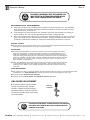
UNLOADER ADJUSTMENT
All RAMTEQ machines have the unloader
correctly set at the the factory. Setting an
unloader is a difficult job without the proper
equipment and training. Should the need arise
to change the unloader settings, please contact
your local distributor.
�
WARNING
RAMTEQ 14275
®
General
Unloader
CHANGING THE UNLOADER SETTINGS WITHOUT THE PROPER
EQUIPMENT AND TRAINING MAY RESULT IN NON-WARRANTY
DAMAGE TO THE PUMP.
northwest freeway
Houston, TX 77040
phone: 713.983.6000
fax: 713.983.6405
300-00004-01
7/06
Operator’s Manual
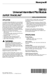
Page 8
9
7
10
11
1
6
5
Part
Part #
4
3
2
Description
Pump, Motor, and Power Plate Assembly
1
Pump Pulley, and Belts
584-00003-01
Pulley 2TB80
516-00004-01
Bushing, SP, split taper, Q1-24mm
586-00003-32
Belt, B59
2
Pump Assembly
220-00025-01
Pump, AR#XWA8G30N-SX (left handed shaft)
500-00011-05
Screw, Black oxide,Hex recess 10-1.5x18mm 513-00001-04
Washer, SS, Helical spring lock, 10mm
3
Belt Tensioner Assembly
585-00015-01
Fenner drive belt tensioner #FS0108
513-00004-01
Washer, Helical spring lock, 3/8, SAE
505-00003-04
Bolt, SS, Hex, 3/8-16x1.25"
4
Motor Pulley Assembly
584-00003-01
Pulley 2TB80
516-00006-01
Motor Bushing Q1- 1 5/8
5
Motor and Power Plate Components
200-00008-01
Motor, 15.0HP, 230/60/3, Baldor M2513T 580-00001-03
1" Romex Cable clamp
505-00010-05
1/2-13 x 1.50" hex bolt
513-00019-01
1/2 flat washers
513-00021-01
1/2 lock washers 508-00001-08
1/2 nuts 180-00217-01
HV, Powerplate, Sheet metal frame
180-00211-01
Power Plate, HV
505-00006-09
Bolt, SS, Carriage, 3/8-16x2.5"
505-00003-09
Bolt, SS, Hex, 3/8-16x2.5"
508-00001-03
Nut, SP, Hex, 3/8-16
513-00010-04
Washer, SS, 3/8"ID, 1"OD, .083"THK 513-00004-01
Washer, SS, Helical spring lock, 3/8, SAE
RAMTEQ 14275
®
northwest freeway
Houston, TX 77040
phone: 713.983.6000
fax: 713.983.6405
Qty
1
1
2
1
4
4
1
1
1
1
1
1
1
4
8
4
4
1
1
4
2
6
8
6
300-00004-01
7/06
Operator’s Manual
Page Part
Part #
Description
Float Tank and Pump Plumbing
6
Float Tank Inlet Plumbing
190-00001-01
HV, Float Tank (modified diesel tank)
180-00175-01
Strap,Tank Torsion, 304SS, 3 ga. .244"
518-00002-01
Fitting, 1/2 fpt ID x float tank bulkhead
565-00001-01
O-ring, 2-120, 70 durometer nitrile
522-00010-01
Connector, Garden hose, 3/4 swivel x 1/2 mpt close 515-00002-01
Washer, rubber for 3/4" ghf
557-00001-03
Hose clamp, SS, #126
280-00002-05
Hose, low pressure, 3/4" ID, (two pieces 6")
535-00011-01
Y, connector, 3/4" YA-34
531-00006-05
Hose barb, 3/4HB x 90°x 3/4FPT (gray PVC)
569-00030-01
Valve, Float, High capacity diaphragm type, 3/4
280-00002-03
Hose, low pressure, 1/2" ID,
557-00001-01
Hose, Clamp, SS, 0.25"-0.63" diam.
530-00002-04
Elbow, brs, 1/4mpt x 90° x 3/8hb
518-00001-01
Plug, brs, 1/4nptm hex
Float Tank Outlet Plumbing to Pump
518-00002-01
Fitting, 1/2nptf I.D.float tank bulkhead
526-00001-03
Nipple, close, brs, 1/2"nptm
554-00002-01
Fitting, inlet strainer
518-00004-02
Plug, brs, 3/8 nptm hex MODIFIED
554-00003-05
Conn, brs, 1/2nptm x 3/4barb
538-00007-01
Tee,branch,brs,1/2 npt
582-00003-02
Bushing, brass, 1/2 mpt x 1/4 fpt
554-00003-07
Connector, brass, 1/4 mpt x 1/4 hb
530-00014-06
Elbow, brass, street 1/2 90°
Float Tank Bracket
180-00214-01
Bracket, float tank HV
505-00006-03
Bolt, SS, Carriage, 3/8-16x1"
508-00001-03
Nut, SP, Hex, 3/8-16
513-00009-03
Washer, SS, 5/16"ID
513-00004-01
Washer, SS,Helical spring lock, 3/8, SAE
Pump Plumbing and Components
557-00001-03
Hose clamp, SS, #122
280-00002-05
Hose, low pressure, 3/4" ID, 200PSI, black
530-00014-04
Elbow, brass, street, 3/4"
582-00004-04
Bushing, brass, 3/4nptm x 1/2nptf
530-00004-04
Elbow, brs, 1/2"nptm x 1/2" barb, 90°
557-00001-02
Hose clamp, SS, 0.40"-0.90" diam.
281-00004-01
Swivel, brs, #8jic fem x1/2 barb
284-00012-02
1/2" Hose, 40" long crimmped fittings 528-00002-02
Elbow, street, sp, 3/8nptm x 3/8nptf, 90°
517-00002-01
Bushing, SP, 3/8 nptm x 1/4 nptf
574-00002-01
Pressure switch, GP
574-00008-01
Phoenix Valve (Flow Switch GP100329)
230-00011-01
Pulsar Unloader 3KHP
Chemical Injection
557-00001-01
Hose clamp, SS, 0.25"-0.63"diam
554-00003-07
1/4 npt x 1/4 hose barb BRASS
530-00002-02
Elbow, brs, 1/4nptm x 1/4 barb, 90°
285-00002-01
Tubing, clear, 1/4"ID, 3/8"OD
570-00002-01
Check valve, plastic, .25", w/ screen
513-00019-01
1/2 flat washer
567-00018-02
Grommet, 11/16" ID
569-00026-01
Valve, Soap control Coil Plumbing
Inlet and Outlet
524-00004-01
Pipe nipple, galv, 1/2nptm x 2.5"long
536-00006-05
Tee, box, SP,1/2nptf
554-00007-04
QC coupler socket, brs, 1/2", nptf
284-00013-01
1/2" high pressure hose, 24" long, crimped fittings
524-00002-05
Nipple, SP, 1/2 mpt
557-00001-02
Clamp, hose, .400-.900
230-00011-01
Pulsar unloader less outlet checkvalve
280-00002-02
Hose low pressure 3/8 530-00003-04
Elbow , brass, 3/8 mpt x 3/8 hb x 90°
518-00004-01
Plug, brs, 3/8nptm hex
540-00004-02
Coupling, SP, 1/2
528-00006-02
Elbow, Street, SP 1/2"
513-00022-02
Washer, SS, 7/8 ID Flat
524-00012-03
Nipple, Sch 80, 1/2 close, galv.
RAMTEQ 14275
®
northwest freeway
Houston, TX 77040
phone: 713.983.6000
fax: 713.983.6405
Qty
1
1
1
1
1
1
1
46"
1
2
2
2.6"
2
1
1
1
1
1
1
1
1
1
1
1
1
2
2
2
2
1
1
1
1
2
1
1
2
1
1
1
1
3
1
1
96"
1
1
1
1
1
2
1
1
1
1
1
55"
1
1
1
1
2
1
300-00004-01
7/06
Operator’s Manual
Part
Page Part #
Burner Ring Components
7
Burner Assembly
504-00007-02
513-00003-01
513-00009-03
508-00001-02
180-00102-02
569-00009-01
501-00004-01
285-00004-01
250-00015-01
517-00005-01
524-00006-02
524-00011-01
528-00010-02
560-00002-01
524-00011-04
524-00011-05
528-00008-12
569-00021-01
180-00209-01
505-00006-03
513-00009-03
513-00004-01
508-00001-03
Burner Roof Components Description
Qty
U-bolt, 1.5" wide x 2" long, 5/16-18 un
Washer, Helical spring 5/16"
Washer, SS, 5/16"ID
Nut, SP, Hex 5/16-18
Pilot bracket for round ring burner, for X88
Pilot, Burner assbly, #Q379A1015 Scr, SS, Slot Cap, No.12x32, .250"
Tubing, coiled, aluminum 3003
X-88 Solarflo Gas Burner Ring, #52 spuds
1 1/4" to 1" bushing steel
1" close pipe nipple Black Pipe
Nipple, Black pipe, 1"npt x 1.5"
Elbow, Black pipe 1" Union, Black pipe 1"
Nipple, Black pipe, 1"npt x 5"
Nipple, Black pipe, 1"npt x 6"
Ell, Street, 45° 1"
Valve, Regulator, NG/LP, Robertshaw #453501532
HV, Gas pipe bracket
Bolt, SS, Carriage, 3/8-16 x 1"
Washer, SS, 5/16
Washer, SS, Helical spring lock 3/8
Nut SP 3/8-16
1
2
2
2
1
1
2
2.75'
1
1
1
2
3
1
1
1
1
1
1
2
2
2
2
8
Roof Panel Hardware
180-00212-01 HV, Coil Roof
505-00006-03 Bolt, SS, Carriage, 3/8-16x1"
508-00001-03 Nut, SS, Hex, 3/8-16
513-00009-03 Washer, SS, Plain, 5/16 wide
513-00004-01 Washer, SS, Helical spring lock, 3/8, SAE
Coil
Assembly
9
Coil Hardware
155-00007-01 HV, 23 Dia.Coil, 30" tall, 6 pancake
180-00037-01 Bracket, Coil, Universal
505-00003-09 Bolt, SS, Hex, 3/8-16x2.5"
505-00003-03 Bolt, SS, Carriage, 3/8-16 x 1"
508-00001-03 Nut, SP, Hex, 3/8-16
513-00010-04 Washer, SS, 3/8"ID,1"OD, .083"THK
513-00004-01 Washer, SS, Helical spring lock, 3/8, SAE
191-00006-01 Insulation, blanket, 1", 24"wide, 4# x 6.25'
191-00006-01 Insulation, blanket, 1", 6"wide, 4# x 6.25'
180-00215-01 HV, Coil Cap
191-00006-01 Insulation, blanket, 1", 24"wide, 4#
180-00203-01 HV, Galvanized Coil Wrap
500-00004-01 #10 self drilling sheetmetal screws
Panels and Frame Assembly
10
RAMTEQ 14275
®
Stainless Panels and Hardware
180-00207-01 HV, closeout panel, large
505-00001-03 Bolt, SS, Hex, 1/4-20, 1"
513-00008-01 Washer, SS, Plain,1/4, Narrow
180-00208 -01HV, closeout panel, small
505-00001-03 Bolt, SS, Hex, 1/4-20, 1"
513-00008-01 Washer, SS, Plain, 1/4, Narrow
Corner Post Pre-Assembly
180-00201-02 HV, corner posts with openings 180-00201-01 HV, corner posts without openings 508-00002-08 Nut, SP, Cage, 1/4-20, .125-.156
567-00027-01 Plug, dome, nylon, 2.5", heyco #2790
Crossbar Pre-Assembly
180-00206-01 HV, Crossbar
Crossbars to Cornerposts
505-00006-07 Bolt, SS, Carriage, 3/8-16x2.0"
508-00001-03 Nut, SP, Hex, 3/8-16
northwest freeway
Houston, TX 77040
phone: 713.983.6000
fax: 713.983.6405
1
8
8
8
8
1
3
2
1
3
6
3
1
1
1
2'
1
5
3
24
24
1
8
8
2
2
39
1
9
18
18
300-00004-01
7/06
Operator’s Manual
Part
Part #
Page 10
Description
Panels and Frame Assembly Continued
513-00010-04
Washer, SS, 3/8"ID, 1"OD, .083"THK
513-00004-01
Washer, SS, Helical spring lock, 3/8, SAE
Leveler Bolts to Reinforcement Plates 505-00012-11
5/8-13 x 3.00" hex bolt
508-00009-05
5/8-13 Jam nuts
513-00011-01
Washer, SS, 5/8"ID
Reinforcement Plates to Crossbars & Crossbeam
180-00205-01
HV, Reinforcement Plate
505-00006-03
Bolt, SS, Carriage, 3/8-16x1"
508-00001-03
Nut, SP, Hex, 3/8-16
513-00009-03
Washer, SS, 5/16"ID, .875"OD, .083"THK
513-00004-01
Washer, SS, Helical spring lock, 3/8, SAE
Powerplate Mounting Bar To Frame
180-00215-01
HV, Powerplate, Mounting Bar
504-00002-23
Bolt, countersunk, 5/16-18x 1 513-00009-03
Washer, SS, 5/16"ID, .875"OD, .083"THK
513-00003-01
Washer, SS, Helical spring lock, 5/16, SAE
509-00001-02
Nut, SS, Hex, 5/16-18
Control
Box Assembly
11
Control Box 180-00217-01
Control Box
508-00002-08
Nut,SP,Cage,1/4-20,.125-.156
504-00002-23
Scr,cap,cntrsnk,hex sckt,5/16-18x1",blk
508-00001-02
Nut,SP,Hex,5/16-18
513-00003-01
Washer,SS,Hel Sprg Lk, 5/16,SAE
513-00009-03
Washer,SS,5/16" ID
Control Box Components
180-00217-01
Control Box
571-00001-02
Timer,shutdown,for NG,TSB2190
505-00007-05
Bolt,SS,Hex,No.10-24x1.25"
513-00007-01
Washer,SS,Plain,No.10
513-00001-02
Washer,SS,Hel Sprg Lk,No.10-24,SAE
508-00001-04
Nut,SP,Hex,#10-24
456-00001-01
Terminal Block,#600A-GP-12
505-00008-02
Screw,SS,Pan head slotted,No.6-32x.75"
512-00005-01
Washer,SP,Flat,No.6,SAE
513-00001-03
Washer,SS,Helical spring lock, No.6-32, SAE
508-00001-06
Nut,SP,Hex,#4-40
450-00001-01
Switch,rocker,low-amp
450-00007-01
Switch,momentary,Carlingswitch,24V3 455-00008-01
Pulse relay C-BATES S89R5ABD1-24
571-00006-01
Hourmeter, Hobbs, 24V BRACKET MT
451-00016-01
Contactor, 10HP, 3PH, ABB#B40C-F
451-00013-01
Overload, thermal, ABB#T75DU42
573-00004-01
Thermostat, 250 degree
574-00002-01
Pressure switch
580-00001-02
Conn, SP, cable grip, 3/4"
580-00001-03
1" Romex connector
Ignition Control Assembly
11
RAMTEQ 14275
®
Control Box and Components
430-00013-01
Cable, Pilot ignition, #394800-30
455-00003-01
Controller, #S8600M1013
180-00102-01
Pilot bracket for round ring burner
505-00001-01
Bolt, SS, Hex,1/4-20, .5"
459-00003-01
Enclosure, Vnykier #VM775CT
505-00008-02
Screw, SS, Pan head slotted, No.6-32x.75"
512-00005-01
Wshr, SP, Flat, No.6, SAE
513-00001-03
Wshr, SS, Helical spring lock, No.6-32, SAE
508-00001-06
Nut, SP, Hex, #4-40
580-00001-04
1/2" cable grips
567-00011-01
Nut, nylon, 1/2", heyco #8463
505-00003-03
Bolt, SS, Hex, 3/8-16x1"
513-00010-04
Washer, SS, 3/8"ID, 1"OD, .083"THK
513-00004-01
Washer, SS, Helical spring lock, 3/8, SAE
508-00001-03
Nut, SP, Hex, 3/8-16
430-00016-02
High temp ground lead 22 GA.
northwest freeway
Houston, TX 77040
phone: 713.983.6000
fax: 713.983.6405
Qty
18
18
4
4
4
4
16
16
16
16
3
12
12
12
12
1
3
4
4
4
4
1
1
1
2
1
1
1
4
4
4
4
2
1
3
1
1
1
1
2
1
1
1
1
1
2
1
4
4
4
4
3
3
2
4
2
2
22"
300-00004-01
7/06
Operator’s Manual
Page 11
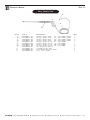
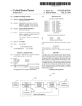
Hose, Wand & Gun
4
3
1
5
2
Ref.#
Part #
Description
Qty.
1a 270-00011-01 Nozzle, Water #9.0 0º (HV 1000, 1500) 1
1b 270-00011-02 Nozzle, Water #9.0 15º (HV 1000, 1500) 1
1c 270-00011-03 Nozzle, Water #9.0 25º (HV 1000, 1500) 1
1d 270-00011-04 Nozzle, Water #9.0 40º (HV 1000, 1500) 1
1e 270-00017-01 Nozzle, Water #11.0 0º (HV 2000) 1
1f 270-00017-02 Nozzle, Water #11.0 15º (HV 2000) 1
1g 270-00017-03 Nozzle, Water #11.0 25º (HV 2000) 1
1h 270-00017-04 Nozzle, Water #11.0 40º (HV 2000) 1
1
2 265-00001-01 36” Wand, Insulated 3 275-00001-01 ST1500 Trigger Gun 1
1
4 552-00002-01 3/8” Quick Connect, Male 5 284-00004-01 Hose 3/8” X 50” 1
RAMTEQ 14275
®
northwest freeway
Houston, TX 77040
phone: 713.983.6000
fax: 713.983.6405
300-00004-01
7/06
RAMTEQ 14275
®
northwest freeway
Houston, TX 77040
phone: 713.983.6000
Y
BLU
BLU
BLU
PUMP SW
BLU
BLU
BLU
BLU
WHT
BLU
BLU
BLK
1
2
3
Y
BLU
24 V
W
DETERGENT SW
BLU
Y
BLU
Y
BLACK
HOURMETER
BLU
BLU
O
BLK/RED STRIPE 460V
208/230V
BLU
Y
BLK
RED
BLU
BLU
BLU
BURNER SW
Y
BLK
HIGH LIMIT SWITCH
WHT
New Wiring Effective 10/01/2003
REMOTE COMMON
REMOTE 24V POWER
DETERGENT ON
REMOTE BURNER ON
REMOTE PUMP ON
BLU
BLU
DETERGENT
VALVE
(REMOTE
KIT ONLY)
ST 261 UNLOADER SW
BLK
4
TIMER
5
1
R
THERMOSTAT
P
BLK
A1
Y
Y
A2
BLU
R
BLU
96
M1
Y
OL
95
BLU
BLK
MV
3L2
T2
OL
5L3
GND
BLU
14
AUX
13
TH-W
BLU
24V
BLU
Y
CONTACTOR
G
24V
(GND)
R
PRESSURE SW
BRN
Removed for 1 PH units
T3
OL
M1
B
PV
ELEC
MOTOR
T1
OL
M1 M1
1L1
W
MV
PV
HONEYWELL S8610U
R
B
W
TR
TH
+
-
GAS
VALVE
(PROVIDED BY CUSTOMER)
LINE POWER INPUT
PILOT
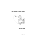
208/230 and 460 VOLT
ALL SINGLE AND THREE
PHASE UNITS
HV SERIES NG/LP
GAS UPGRADE
ELECTRICAL SCHEMATIC
Added for 1 PH units
R
SPARK
Operator’s Manual
Page 12
fax: 713.983.6405
300-00004-01
7/06
Operator’s Manual
RAMTEQ 14275
®
northwest freeway
Page 13
Houston, TX 77040
phone: 713.983.6000
fax: 713.983.6405
300-00004-01
7/06
Operator’s Manual
Page 14
troubleshooting
problem
cause
action
Low Water Pressure
Insufficient water source
Old or incorrect nozzle
Plumbing or hose leak
Obstruction in spray nozzle
Chemical valve open
Unloader valve worn
Pump valves dir ty or worn
Check hose size/water source
Replace nozzle
Tighten, repair or replace leak
Clean or replace nozzle
Close valve or submerge hose
Replace unloader
Clean or replace packing/valves
No Chemical Flow Detergent valve closed
Low detergent level
Chemical screen dir ty
Open detergent valve
Fill detergent container
Clean detergent screen
Pilot will not light Burner will not fire No fuel Burner switch turned off
Thermostat set too low
Defective pressure switch
Trigger not pulled Gas valve turned off
No voltage to valve Pilot orifice plugged
Defective ignition module
Defective transformer Defective thermostat Faulty rocker switch
Igniter not working
Ensure proper gas flow
Turn burner switch on
Reset thermostat
Replace pressure switch
Burner should fire only when trigger pulled
Turn gas valve on
Check voltage between valves
Remove orifice & clean
Check voltage to & through module.
Replace transformer
Replace thermostat
Replace switch
Test for spark and continuity between
ignition wire and ground
WARNING: High voltage ignitor can cause electrical shock.
Pilot lights, but burner will not fire Check for 24v between main valve and pilot valve
If no voltage at the valve, replace module If voltage, replace valve
Burner fires, but goes out Check for continuity between ignition cable and ground wire
Faulty ignition module
Excess draft Assure good ground
Replace module
Protect from windy conditions
Discharge water temperature
too high Faulty thermostat Water restriction Incoming gas pressure too high
Replace thermostay
Clean or replace spray nozzle
Descale coil
Check and lower gas pressure
Discharge water temperature not reaching maximum temp setting.
Worn spray nozzle
Gas pressure too low
Draft under burner manifold Replace spray nozzle with proper size
Increase gas pressure
Prevent down draft with installation
ofdraft diver ter
Burner continues to fire even when water not being sprayed Faulty pressure switch Main gas valve stuck open Replace pressure switch.
Replace main gas valve.
Pressure
Nozzle is dir ty
Defective relief valve
Unloader adjusted incorrectly
Restriction on discharge hose
Scale restricting flow in coil Clean or replace nozzle
Replace relief valve
Adjust unloader valve
Remove nozzle and flush line
Clean coil
Relief Valve Leaks Pump Motor Not Running
Pump motor switch off
GFCI tripped
No voltage to machine
Clogged water nozzle Insufficient voltage/amperage Turn on pump motor switch
Reset and test GFCI
Check power source
Clean water nozzle
Use proper drop cord
Pump Noisy
Air in suction line Pump valves dir ty Check valve springs worn
Low pump oil Pump bearings are worn
Incoming water too hot
Check inlet water fittings
Clean/replace pump valves
Replace check valves
Add SEA 30wt. non-detergent
Replace/rebuild pump
Reduce temperature/ambient
Water In Oil
High humidity environment Oil seal worn Plunger packing worn
Change oil frequently
Check and replace oil seal
Check and replace packing
Water Dripping/Pump
Plunger packing is worn
Plunger retainer oil ring worn Cracked ceramics Install new packing kit
Replace oil ring
Replace ceramics
Oil Dripping
Oil seal worn
Cracked manifold Check and replace oil seals
Replace manifold
Unloader not adjusted
Valves worn
Dir t or blockage in valves
Pump sucking air Worn plunger packing
Adjust to specifications
Replace with valve kit
Clean or replace valve
Check water/detergent supply
Replace packing kit
Extended period in bypass
Pull trigger gun for water flow
Fluctuating Pressure
Pump Head Overheating RAMTEQ 14275
®
northwest freeway
Houston, TX 77040
phone: 713.983.6000
fax: 713.983.6405
300-00004-01
7/06
RAMTEQ
Limited One Year
WARRANTY
Ramteq Incorporated ("RAMTEQ") warrants that the Product you have purchased from RAMTEQ or from an
Authorized RAMTEQ Reseller is free from defects in materials or workmanship under normal use for a period of one
(1) year from the date of purchase. This warranty extends only to you, the original Purchaser. It is not transferable to anyone who subsequently purchases the Products from you. This warranty specifically excludes expendable
items, including but not limited to hoses, seals, nozzles and gunjets. RAMTEQ manufacturers warrant certain components of the Products for periods greater than one (1) year. MOTORS, GENERATORS, PUMPS, COILS, BURNERS
AND ENGINES ARE WARRANTED BY THEIR RESPECTIVE MANUFACTURERS, AND SERVICED THROUGH THESE
MANUFACTURERS' LOCAL AUTHORIZED SERVICE CENTERS. Specific warranty details can be found on the individual manufacturers website. RAMTEQ CANNOT PROVIDE WARRANTY ON THESE ITEMS.
During the warranty period, RAMTEQ will repair or replace defective parts, at the option of RAMTEQ.
This limited warranty does not extend to any Product not purchased from RAMTEQ or from an Authorized RAMTEQ
Reseller. This limited warranty also does not extend to any Product that has been damaged or rendered defective (a)
as a result of accident, misuse or abuse; (b) by operation outside the specifications in the intended applications; (c) by
the use of parts not sold or manufactured by RAMTEQ; (d) by the modification of the Product.
Warranty Disclaimer
EXCEPT AS EXPRESSLY SET FORTH IN THIS WARRANTY, RAMTEQ MAKES NO OTHER WARRANTIES, EXPRESS
OR IMPLIED, INCLUDING ANY IMPLIED WARRANTIES OF MERCHANTABILITY AND FITNESS FOR A PARTICULAR
PURPOSE. RAMTEQ EXPRESSLY DISCLAIMS ALL AND ANY WARRANTIES NOT STATED IN THIS LIMITED
WARRANTY. ANY IMPLIED WARRANTIES THAT MAY HAVE BEEN IMPOSED BY LAW ARE LIMITED TO THE TERMS
OF THIS EXPRESS LIMITED WARRANTY.
Limitation of Remedy
RAMTEQ IS NOT LIABLE FOR ANY DAMAGES CAUSED BY THE PRODUCT OR FAILURE OF THE PRODUCT TO
PERFORM, INCLUDING INCIDENTAL AND CONSEQUENTIAL DAMAGES. THIS LIMITATION APPLIES WHETHER
DAMAGES ARE SOUGHT, OR A CLAIM MADE, AS A CONTRACT CLAIM, AS A TORT CLAIM, OR ANY OTHER
CLAIM.
THIS LIMITATION OF LIABILITY, HOWEVER, WILL NOT APPLY FOR PERSONAL INJURY.
U.S.A. State Laws
Some states do not allow limitation on how long an implied warranty lasts. In such states, the limitations or
exclusions of this Limited Warranty may not apply to you.
Some states do not allow the exclusion or limitation in incidental or consequential damages for consumer products. In
such states, the exclusion may not apply to you. This limited warranty gives you specific legal rights. You may also
have other rights that may vary from state to state. You are advised to consult applicable state laws for a full
determination of your rights.
How to Obtain Warranty Service
TO OBTAIN WARRANTY SERVICE YOU MUST CONTACT RAMTEQ or an AUTHORIZED RAMTEQ RESELLER.
RAMTEQ
®
14275 NORTHWEST FREEWAY
HOUSTON, TX 77040
PHONE: 713.983.6000
FAX: 713.983.6405
300-00001-01
1/13
Ramteq
Manufacturers Warranty Period
Click on pictures to open manufacturers website.
5 years
5 years
3 years
3 years
3 years
3 years
18 months
18/36 months
Ramteq Pressure Washers
14275 NORTHWEST FREEWAY
HOUSTON, TX 77040
1 year
PHONE: 713.983.6000
FAX: 713.983.6405
1/13