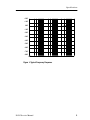
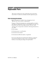
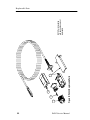
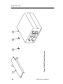
1
Service Manual P6243 1 GHz 10X Active Probe 070-9409-03 Warning The servicing instructions are for use by qualified personnel only. To avoid personal injury, do not perform any servicing unless you are qualified to do so. Refer to all safety summaries prior to performing service. www.tektronix.com Copyright E Tektronix, Inc. All rights reserved. Tektronix products are covered by U.S. and foreign patents, issued and pending. Information in this publication supercedes that in all previously published material. Specifications and price change privileges reserved. Tektronix, Inc., P.O. Box 500, Beaverton, OR 97077 TEKTRONIX, TEK, and TEKPROBE are registered trademarks of Tektronix, Inc. WARRANTY Tektronix warrants that the products that it manufactures and sells will be free from defects in materials and workmanship for a period of one (1) year from the date of shipment. If a product proves defective during this warranty period, Tektronix, at its option, either will repair the defective product without charge for parts and labor, or will provide a replacement in exchange for the defective product. In order to obtain service under this warranty, Customer must notify Tektronix of the defect before the expiration of the warranty period and make suitable arrangements for the performance of service. Customer shall be responsible for packaging and shipping the defective product to the service center designated by Tektronix, with shipping charges prepaid. Tektronix shall pay for the return of the product to Customer if the shipment is to a location within the country in which the Tektronix service center is located. Customer shall be responsible for paying all shipping charges, duties, taxes, and any other charges for products returned to any other locations. This warranty shall not apply to any defect, failure or damage caused by improper use or improper or inadequate maintenance and care. Tektronix shall not be obligated to furnish service under this warranty a) to repair damage resulting from attempts by personnel other than Tektronix representatives to install, repair or service the product; b) to repair damage resulting from improper use or connection to incompatible equipment; c) to repair any damage or malfunction caused by the use of non-Tektronix supplies; or d) to service a product that has been modified or integrated with other products when the effect of such modification or integration increases the time or difficulty of servicing the product. THIS WARRANTY IS GIVEN BY TEKTRONIX IN LIEU OF ANY OTHER WARRANTIES, EXPRESS OR IMPLIED. TEKTRONIX AND ITS VENDORS DISCLAIM ANY IMPLIED WARRANTIES OF MERCHANTABILITY OR FITNESS FOR A PARTICULAR PURPOSE. TEKTRONIX’ RESPONSIBILITY TO REPAIR OR REPLACE DEFECTIVE PRODUCTS IS THE SOLE AND EXCLUSIVE REMEDY PROVIDED TO THE CUSTOMER FOR BREACH OF THIS WARRANTY. TEKTRONIX AND ITS VENDORS WILL NOT BE LIABLE FOR ANY INDIRECT, SPECIAL, INCIDENTAL, OR CONSEQUENTIAL DAMAGES IRRESPECTIVE OF WHETHER TEKTRONIX OR THE VENDOR HAS ADVANCE NOTICE OF THE POSSIBILITY OF SUCH DAMAGES. Table of Contents General Safety Summary . . . . . . . . . . . . . . . . . . . . . . . . . . . . iii Specifications . . . . . . . . . . . . . . . . . . . . . . . . . . . . . . . . . . . . . . 1 Operating Basics . . . . . . . . . . . . . . . . . . . . . . . . . . . . . . . . . . . Maximum Non-destructive Input Voltage . . . . . . . . . . . . . . . . . Input Linear Dynamic Range . . . . . . . . . . . . . . . . . . . . . . . . . . 9 9 9 Theory of Operation . . . . . . . . . . . . . . . . . . . . . . . . . . . . . . . . Probe Head and Cable Assembly . . . . . . . . . . . . . . . . . . . . . . . Compensation Box . . . . . . . . . . . . . . . . . . . . . . . . . . . . . . . . . . . 10 10 11 Performance Verification . . . . . . . . . . . . . . . . . . . . . . . . . . . . Equipment Required . . . . . . . . . . . . . . . . . . . . . . . . . . . . . . . . . Equipment Setup . . . . . . . . . . . . . . . . . . . . . . . . . . . . . . . . . . . . Output Zero . . . . . . . . . . . . . . . . . . . . . . . . . . . . . . . . . . . . . . . . DC Attenuation Accuracy . . . . . . . . . . . . . . . . . . . . . . . . . . . . . 12 12 12 13 13 Maintenance . . . . . . . . . . . . . . . . . . . . . . . . . . . . . . . . . . . . . . . Replacing TEKPROBE Interface Pins . . . . . . . . . . . . . . . . . . Removing and Replacing the Compensation Box Covers . . . . Removing and Replacing the TEKPROBE Interface Collar . Inspection and Cleaning . . . . . . . . . . . . . . . . . . . . . . . . . . . . . . Replacement Parts . . . . . . . . . . . . . . . . . . . . . . . . . . . . . . . . . . . Preparation for Shipment . . . . . . . . . . . . . . . . . . . . . . . . . . . . . . 16 16 17 19 20 20 20 Replaceable Parts . . . . . . . . . . . . . . . . . . . . . . . . . . . . . . . . . . . 21 P6243 Service Manual i Table of Contents List of Figures Figure 1: Typical Frequency Response . . . . . . . . . . . . . . . . . . . Figure 2: Typical Linearity Error vs. VIN . . . . . . . . . . . . . . . . . Figure 3: Typical Input Impedance vs. Frequency . . . . . . . . . . Figure 4: Typical Non-Destructive Peak Voltage Derating vs. Frequency . . . . . . . . . . . . . . . . . . . . . . . . . . . . . . . . . . . . . . . Figure 5: P6243 Simplified Schematic Diagram . . . . . . . . . . . Figure 6: TEKPROBE Interface . . . . . . . . . . . . . . . . . . . . . . . . Figure 7: P6243 DC Attenuation Accuracy Setup . . . . . . . . . . Figure 8: Replacing TEKPROBE Interface Pins . . . . . . . . . . . Figure 9: Removing the Compensation Box Covers . . . . . . . . . Figure 10: Replacing the Compensation Box Cover . . . . . . . . . Figure 11: Replacing the TEKPROBE Collar . . . . . . . . . . . . . . Figure 12: P6243 Replaceable Parts . . . . . . . . . . . . . . . . . . . . . Figure 13: P6243 Standard Accessories . . . . . . . . . . . . . . . . . . Figure 14: P6243 Optional Accessories . . . . . . . . . . . . . . . . . . 3 4 5 6 10 11 14 16 17 18 19 22 24 26 List of Tables Table 1: Warranted Electrical Specifications . . . . . . . . . . . . . . Table 2: Typical Electrical Characteristics . . . . . . . . . . . . . . . . Table 3: Physical Characteristics . . . . . . . . . . . . . . . . . . . . . . . . Table 4: Environmental Characteristics . . . . . . . . . . . . . . . . . . Table 5: Certifications and Compliances . . . . . . . . . . . . . . . . . Table 6: Equipment Required for Performance Verification . . ii 1 2 7 7 8 12 P6243 Service Manual General Safety Summary Review the following safety precautions to avoid injury and prevent damage to this product or any products connected to it. Only qualified personnel should perform service procedures. Injury Precautions Avoid Electric Overload. To avoid electric shock or fire hazard, do not apply a voltage to a terminal that is outside the range specified for that terminal. Do Not Operate Without Covers. To avoid electric shock or fire hazard, do not operate this product with covers or panels removed. Do Not Operate in Wet/Damp Conditions. To avoid electric shock, do not operate this product in wet or damp conditions. Do Not Operate in an Explosive Atmosphere. To avoid injury or fire hazard, do not operate this product in an explosive atmosphere. Product Damage Precautions Use Proper Power Source. Do not operate this product from a power source that applies more than the voltage specified. Do Not Operate With Suspected Failures. If you suspect there is damage to this product, have it inspected by qualified service personnel. Do Not Immerse in Liquids. Clean the probe using only a damp cloth. The cloth must be dampened with either isopropyl alcohol or a mild detergent and water solution. Do not use any other chemicals or abrasives to clean the probe. P6243 Service Manual iii General Safety Summary Safety Terms and Symbols Terms in This Manual. These terms may appear in this manual: WARNING. Warning statements identify conditions or practices that could result in injury or loss of life. CAUTION. Caution statements identify conditions or practices that could result in damage to this product or other property. Terms on the Product. These terms may appear on the product: DANGER indicates an injury hazard immediately accessible as you read the marking. WARNING indicates an injury hazard not immediately accessible as you read the marking. CAUTION indicates a hazard to property including the product. Symbols on the Product. These symbols may appear on the product: DANGER High Voltage iv Protective Ground (Earth) Terminal ATTENTION Refer to Manual Double Insulated P6243 Service Manual Specifications The warranted specifications in Table 1 apply to a P6243 Active Probe when the probe and the host instrument are allowed to warm up for 20 minutes before measurements are taken. The warranted specifications that appear in boldface type are specifications checked in the Performance Verification section of the service manual. The specifications in Tables 2 through 5 are provided as general information for your convenience. CAUTION. Do not apply voltages beyond the non-destructive input voltage range to the probe. Damage to the probe or circuit under test may result. Refer to Figure 4 on page 6. Table 1: Warranted Electrical Specifications Analog Bandwidth (probe only) at +20 °C to +30 °C (+68 °F to +86 °F) >1.0 GHz DC Attenuation Accuracy (probe only) at +20 °C to +30 °C (+68 °F to +86 °F) 10:1 ±2% Output Zero at +20 °C to +30 °C (+68 °F to +86 °F) ±10 mV or less at output of probe Rise Time (probe only) at +20 °C to +30 °C (+68 °F to +86 °F) <350 ps P6243 Service Manual ±100 mV or less displayed on screen with TEKPROBE interface 1 Specifications Table 2: Typical Electrical Characteristics Frequency Response (probe only) See Figure 1 Linear Input Dynamic Range -- 8 V to + 8 V. (Equivalent to -- 0.8 V to + 0.8 V at the output of the probe) Linearity 4% or less of dynamic range Linearity Error vs. VIN See Figure 2 Input Resistance 1 MΩ at DC. (See Figure 3) Input Capacitance <1.0 pF Non-Destructive Input Voltage Range -- 15 V to + 15 V (DC + peak AC) (See Figure 4 on page 6) DC Offset Drift 100 V/°C or less at output of probe 1 mV/°C or less displayed on screen with TEKPROBE interface Delay Time 2 5.3 ns ±0.2 ns P6243 Service Manual Specifications +2 dB +1 dB 0 dB - 1 dB - 2 dB - 3 dB - 4 dB - 5 dB - 6 dB - 7 dB - 8 dB 1 MHz 10 MHz 100 MHz 1 GHz Figure 1: Typical Frequency Response P6243 Service Manual 3 Specifications 150 mV 100 mV Display Error 50 mV 0 mV - 50 mV - 100 mV - 150 mV - 20 V - 10 V 0V VIN 10 V 20 V Figure 2: Typical Linearity Error vs. VIN 4 P6243 Service Manual Specifications 10 MΩ 1 MΩ 100 kΩ 10 kΩ 1 kΩ 100 Ω 10 Ω 100 Hz 1 kHz 10 kHz 100 kHz 1 MHz 10 MHz 100 MHz 1 GHz Figure 3: Typical Input Impedance vs. Frequency P6243 Service Manual 5 Specifications 25 V 20 V 15 V 10V at 1 GHz 10 V 6V at 3 GHz 5V 0V 1 MHz 10 MHz 100 MHz 1 GHz Figure 4: Typical Non-Destructive Peak Voltage Derating vs. Frequency 6 P6243 Service Manual Specifications Table 3: Physical Characteristics Net Weight 63.8 g (2.25 ounces) Cable Length 1.3 meter (4.3 ft) Table 4: Environmental Characteristics Operating Temperature 0 °C to +50 °C (+32 °F to +122 °F) The environmental exposure is the procedure stated in Tektronix Design Standard 062--2847--00 for Class 5 equipment Non-operating Temperature -- 40 °C to + 71 °C (-- 40 °F to + 160 °F) The environmental exposure is the procedure stated in Tektronix Design Standard 062--2847--00 for Class 5 equipment Humidity The environmental exposure is the procedure stated in Tektronix Design Standard 062--2847--00 for Class 5 equipment Packaged Product Vibration and Shock The packaged product qualifies under the Distribution Cycle 1 Assurance Level II for packaged products 0 -- 20 lbs. Test 2 for Warehouse and Vehicle Stacking (Compression) is omitted Tektronix standard 062--2858--00, Rev. B, Class 5 Altitude P6243 Service Manual Operating: 4,572 m (15,000 ft) Non--Operating: 15,240 m (50,000 ft) 7 Specifications Table 5: Certifications and Compliances EC Declaration of Conformity Meets the intent of Directive 89/336/EEC for Electromagnetic Compatibility. Compliance was demonstrated to the following specifications as listed in the official Journal of the European Communities: EN 50081--1 Emissions: EN 55022 FCC Compliance 8 EN 60555--2 Class B: Radiated and Conducted Emissions Power Harmonics EN 50082--1 Immunity: IEC 801--2 IEC 801--3 IEC 801--4 IEC 801--5 Electrostatic Discharge RF Radiated Fast Transients Surge Emissions comply with FCC Code of Federal Regulations 47 CFR, Part 15, Subpart B, Class A P6243 Service Manual Operating Basics Please follow these operating guidelines to get optimum performance from your P6243 Active Probe. Maximum Non-destructive Input Voltage The P6243 Active Probe is electrically protected against static voltage; however, applying voltages above its design limits may damage the probe tip amplifier. Please refer to the Specifications section of this manual for the maximum non-destructive input voltage and frequency derating information. Input Linear Dynamic Range The probe head amplifier used by the P6243 Active Probe has a limited linear operating range. To keep the input linearity error less than 4% you must limit the signal input voltage to ±8 V (DC + peak AC). NOTE. The probe can tolerate input voltages of ±15 V without damage; however, the linearity error specification does not apply to input voltages exceeding ±8 V (DC + peak AC). P6243 Service Manual 9 Theory of Operation There are no user replaceable parts within the probe or the compensation box; however, this theory of operation is provided to assist you in isolating failures to either the probe or the host oscilloscope. Refer to Figure 5 for a simplified schematic of the probe. Probe Head Compensation Box Oscilloscope Probe Tip Signal Out Probe-Tip Amplifier EEPROM Probe Cable Probe ID Out Clock In +5 V -5 V Ground TEKPROBE Interface Figure 5: P6243 Simplified Schematic Diagram Probe Head and Cable Assembly The probe head assembly contains an active amplifier circuit that buffers and amplifies the input signal. The amplifier receives power from the compensation box assembly via the cable assembly. All signal amplification and buffering is performed in the probe head assembly. No further amplification takes place in the compensation box. 10 P6243 Service Manual Theory of Operation Compensation Box The compensation box contains the following circuits: H Probe identification EEPROM H TEKPROBE interface Probe Identification EEPROM The probe identification EEPROM is used to configure the oscilloscope to the probe. The EEPROM receives a clock input from the oscilloscope, and information about the probe is passed to the oscilloscope. TEKPROBE Interface The TEKPROBE interface provides a communication path between the probe and the oscilloscope. Contact pins provide power, signal, and data transfer for the probe identification EEPROM. Figure 6 shows the TEKPROBE interface pin functions. Refer to the service documentation of your oscilloscope for more detailed specifications. -5 V Ground Signal Data Clock +5 V Figure 6: TEKPROBE Interface P6243 Service Manual 11 Performance Verification This section contains the procedures for verifying the performance of the P6243 Active Probe. Equipment Required Table 6: Equipment Required for Performance Verification Item Description Performance Requirement Recommended Example Oscilloscope TEKPROBE interface Tektronix TDS 744A TEKPROBE Power Supply Tektronix 1103 DC Power Supply 10.00 ±.01 VDC at 1 mA Tektronix PS281 DC Voltmeter 0.5% accuracy at 2 VDC Tektronix CDM250 Feedthrough Termination 50 Ω ± 0.50 Ω 011-0129-00 BNC to BNC coaxial cable 50 Ω coaxial cable 012-1342-00 BNC to Banana adapter BNC Female to Dual Banana 103-0090-00 Equipment Setup 1. Connect the probe to the oscilloscope. 2. Connect a Y-lead adapter with KlipChip adapters attached to the P6243 probe head. 3. Turn on the oscilloscope and enable the channel. 4. Turn on the power supply and set to +2.00 VDC. 5. Turn on the 1103 power supply. 6. Allow 30 minutes for the equipment to warm up. 12 P6243 Service Manual Performance Verification NOTE. If your oscilloscope has a probe calibration routine, run it before making any of the following checks. Refer to the instruction manual of the oscilloscope for more information. Output Zero Use this procedure to verify the output zero of the probe is within specified limits. 1. Ground the probe tip by connecting the probe tip to the probe ground socket. (Connecting the two KlipChip adapters together is recommended.) 2. Set the oscilloscope input coupling channel to ground and adjust the vertical position to center screen. 3. Set the oscilloscope input coupling channel to DC and set the vertical scale to 100 mV/division. 4. Measure the displayed DC level. The displayed DC level should be 0.00 V ±100 mV. (±10 mV when measured directly without the probe attenuation factor.) DC Attenuation Accuracy Use this procedure to verify the DC attenuation accuracy of the probe. Before beginning, read the procedure through completely. 1. Connect the test equipment as shown in Figure 7. 2. Attach the probe to a TEKPROBE interface on the 1103 power supply. 3. Set the 1103 offset VAR/0V to 0V. 4. Set the multimeter to read DC volts. P6243 Service Manual 13 Performance Verification 5. Connect the probe tip and ground to the power supply using the Y-lead and KlipChip adapters. Digital Multimeter + BNC to Dual Banana Adapter 1103 Power Supply Power Supply -- -- + 50 Ω Precision Terminator Figure 7: P6243 DC Attenuation Accuracy Setup 6. Set the power supply to +2.000 V. (This setting will be referred to later on as Vmax). 7. Record the value measured by the multimeter as M1. (With the 10X attenuation of the probe, the voltage measured will be about +0.200 V.) 8. Set the power supply to - 2.000 V. (This setting will be referred to later on as Vmin). 9. Record the value measured by the multimeter as M2. (With the 10X attenuation of the probe, the voltage measured will be about - 0.200 V.) 14 P6243 Service Manual Performance Verification NOTE. If you are unable to set the power supply precisely, record the settings displayed on the power supply and determine the absolute difference. |Vmax - Vmin| = difference. Divide the difference by 10 to account for the ideal attenuation factor of the probe. For example, 0.42 is the difference between +2.200 and - 2.000, divided by 10. Use this calculated value in place of the denominator of the formula that follows. 10. Determine the percent error by using the formula below: %Error = [M1 − M2 − 1] × 100% 0.4 The calculated error should be ≤2%. NOTE. An unacceptable error value may result if a low tolerance termination is substituted for the recommended termination. P6243 Service Manual 15 Maintenance This section details the maintenance, repair, and troubleshooting procedures for the P6243. Replacing TEKPROBE Interface Pins TEKPROBE interface pins can stick and fail to make contact after time. Periodically check to see that each of the interface pins move freely and fully extends out of the interface. If any pin fails to move freely and fully extend, it should be replaced. To remove a TEKPROBE interface pin, firmly grasp the pointed tip with pliers and pull the pin out of the connector. See Figure 8. No tools are required to install a replacement pin. Insert a new pin into the connector socket as far as possible using finger pressure. If necessary, seat the pin into the connector by pressing the tip gently but firmly against a hard surface, such as a wood block or table top. Figure 8: Replacing TEKPROBE Interface Pins 16 P6243 Service Manual Maintenance Removing and Replacing the Compensation Box Covers Follow these steps to open the compensation box. 1. Press the optional release tool pins into the compensation box cover catches and gently lift the cover off a small distance. Refer to Figure 9. 2. Hold the open edge apart, and use the tool to open the other side of the compensation box. 3. With both sides of the box open, gently separate the two halves of the compensation box. Cover Catches Figure 9: Removing the Compensation Box Covers P6243 Service Manual 17 Maintenance To replace the covers, follow these steps: 1. Align the TEKPROBE interface and the strain relief notches with the tabs on the cover. Refer to Figure 10. 2. Press the cover catches in so that the cover can be lowered. 3. Slide the tab into the notch. 4. Firmly press the pieces together until the cover catches snap into place. Tab Figure 10: Replacing the Compensation Box Cover 18 P6243 Service Manual Maintenance Removing and Replacing the TEKPROBE Interface Collar To remove the TEKPROBE interface collar, firmly grasp the compensation box body with one hand, and the TEKPROBE interface collar with the other hand. Firmly pull the interface collar off. To replace the collar, first note the pin configuration on the compensation box, and their holes in the interface collar. The group of three pins fit through the smaller of the two holes in the interface collar. See Figure 11. Align the tab to the slot and gently press the two pieces together. See Figure 11. Once installed, the TEKPROBE collar should rotate freely to lock and unlock. Tab Slot Figure 11: Replacing the TEKPROBE Collar P6243 Service Manual 19 Maintenance Inspection and Cleaning To prevent damage to probe materials, avoid using chemicals that contain benzine, benzene, toluene, xylene, acetone, or similar solvents. Do not immerse the probe or use abrasive cleaners. Dirt may be removed with a soft cloth dampened with a mild detergent and water solution, or isopropyl alcohol. Replacement Parts Refer to the Replaceable Parts section for a list of customer replacement parts. Due to the sophisticated design of the P6243, there are no user replaceable parts within the probe. Preparation for Shipment If the original packaging is unfit for use or not available, use the following packaging guidelines: 1. Use a corrugated cardboard shipping carton having inside dimensions at least one inch greater than the probe dimensions. The box should have a carton test strength of at least 200 pounds. 2. Put the probe into a plastic bag or wrap to protect it from dampness. 3. Place the probe into the box and stabilize it with light packing material. 4. Seal the carton with shipping tape. 20 P6243 Service Manual Replaceable Parts This section contains a list of the replaceable parts for the P6243 Active Probe. Use this list to identify and order replacement parts. Parts Ordering Information Replacement parts are available from or through your local Tektronix, Inc. service center or representative. Changes to Tektronix instruments are sometimes made to accommodate improved components as they become available and to give you the benefit of the latest circuit improvements. Therefore, when ordering parts, it is important to include the following information in your order: H Part number H Instrument type or model number H Instrument serial number H Instrument modification number, if applicable If a part you order has been replaced with a different or improved part, your local Tektronix service center or representative will contact you concerning any change in the part number. P6243 Service Manual 21 22 Figure 12: P6243 Replaceable Parts 1 2 3 3 NOTE: Parts illustrated with dashed lines are not replaceable Replaceable Parts P6243 Service Manual P6243 205-0191-XX 131-3627-01 200-4276-00 -1 -2 -3 Tektronix Part No. 12 Fig. & Index No. Serial No. Effective Dscont 1 1 1 1 Qty COVER,COMP BOX:TOP AND BOTTOM, W/LABELS & RELEASE TOOLS CONTACT,ELEC:GOLD PLATED TIP SHELL,ELEC CONN:BNC,ABS,DOVE GRAY PROBE, FET ACT:>1.5 GHZ,10X,<1PF,TDS SERIES 12345 Name & Description 80009 80009 80009 80009 Mfr. Code 200-4276-00 131-3627-01 205-0191-XX P6243 Mfr. Part No. Replaceable Parts P6243 Service Manual 23 24 5 Figure 13: P6243 Standard Accessories 6 1 4 3 2 Replaceable Parts P6243 Service Manual P6243 Service Manual 2 1 1 1 1 1 131-- 5638-- 11 214-- 4227-- 00 131-- 5777-- 00 206-- 0364-- XX 070-- 9408-- XX 070-- 9409-- XX 070-- 9410-- XX 070-- 9411-- XX 070-- 9412-- XX -3 -4 -5 -6 1 1 1 MANUAL,TECH:INSTRUCTION,SPANISH,DP,P6243 MANUAL,TECH:INSTRUCTION,GERMAN,DP,P6243 MANUAL,TECH:INSTRUCTION,FRENCH,DP,P6243 MANUAL,TECH:SERVICE,DP,P6243 MANUAL,TECH:INSTRUCTION,ENGLISH,DP,P6243 TIP,PROBE:MICROCKT TEST CONN,CONTACT SPRING ADAPTER:RIGHT ANGLE PROBE,TIP:PACKAGE OF 10 MARKER KIT,ID:CABLE MARKER BAND,2 EACH, VARIOUS COLORS 016-- 1315-- 00 -2 1 LEAD,SET:ONE 3.0 L; ONE 6.O L;STRD,22 AWG & ONE 3.0 L BLACK & WHITE 22 AWG,JACK TIP,TERM CONN MALE PIN;TWO Z-- LEAD 1 12345 Name & Description 196-- 3425-- 00 Qty -1 Serial No. Effective Dscont STANDARD ACCESSORIES Tektronix Part No. 13 Fig. & Index No. TK2548 TK2548 TK2548 TK2548 TK2548 80009 80009 80009 80009 80009 80009 Mfr. Code 070-9412-XX 070-9411-XX 070-9410-XX 070-9409-XX 070-9408-XX 206-0364-XX 131-5777-00 214-4227-00 131-5638-11 016-1315-00 196-3425-00 Mfr. Part No. Replaceable Parts 25 26 Figure 14: P6243 Optional Accessories 1 2 3 4 Replaceable Parts P6243 Service Manual P6243 Service Manual 1103 -4 SMG50 SF502 -3 13-- 4 SF503 003-1383-00 Tektronix Part No. -2 14-1 Fig. & Index No. Serial No. Effective Dscont 1 1 1 1 1 Qty PKG OF 20 TEKPROBE IF PS:W/OFFSET 2 CONN ADAPTER,SUREFOOT:25 MIL JEDEC,PKG OF 12 ADAPTER,SUREFOOT:0.5 MM EIAJ,PKG OF 12 RLSE TOOL,COVER:COMP BOX, POLYCARBONATE OPTIONAL ACCESSORIES 12345 Name & Description 80009 80009 80009 80009 80009 Mfr. Code SMG50 1103 SF502 SF503 003-1383-00 Mfr. Part No. Replaceable Parts 27 28 XEROX BUSINESS SERVICES DIV OF XEROX CORPORATION TEKTRONIX INC 80009 Manufacturer TK2548 Mfr. Code 14150 SW KARL BRAUN DR PO BOX 500 14181 SW MILLIKAN WAY Address CROSS INDEX - MFR. CODE NUMBER TO MANUFACTURER BEAVERTON OR 97077-- 0001 BEAVERTON OR 97077 City, State, Zip Code Replaceable Parts P6243 Service Manual