1
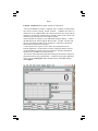
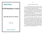
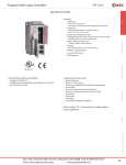
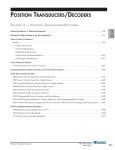
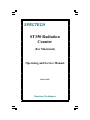
SPECTECH
ST350 Radiation
Counter
(For Macintosh)
Operating and Service Manual
March 2003
Spectrum Techniques
Page 1
Model ST350 RADIATION COUNTER
The ST350 Radiation Counter brings new dimensions to Nuclear Science
instruction and Health Physics training. By incorporating a specialized
microcontroller, many of the features previously found only in multiple
products are now combined in a single inexpensive instrument.
The classical nuclear scaler function has now been extended to include a
timer, preset counter, digital ratemeter with alarm, computer interface and a
battery option for field applications. When constant counting statistics are
required, the preset count mode can be extremely useful and the digital
ratemeter is ideal for contamination survey work. An alarm level may be set to
any pre-selected value and if the count rate exceeds this level, the audible
alarm is sounded warning of a high activity condition.
High voltage is fully variable from 0 to +1200 volts, allowing operation with
many types of GM tubes. The supply is fully regulated and controlled by the
processor for digital accuracy and readout on the display. Extra large LED's are
used for the digital display for clear visual readout under widely differing
ambient light conditions with leading zero suppression for clarity.
Classroom demonstrations and nuclear experiments may now be run directly
from a Macintosh computer using the on-line serial data link built into the
ST350 and LabLink emulation software. All functions of the Radiation
Counter are accessible and may be controlled from the computer, including the
high voltage setting for the GM tube. The Radiation Counter software supplied
produces computer screen displays of all functions including analog emulation
of the ratemeter mode. Real-time data is automatically transferred to the
computer and stored in spreadsheet compatible files. Data analysis and
graphical presentation is now possible using many common spreadsheet
programs bringing new techniques to Nuclear Science education.
Optional batteries may be installed in the ST350 making the instrument fully
portable. An AC to DC line converter/charger is supplied for continuous
benchtop operation with or without the batteries installed.
Page 2
Specifications.
Input: BNC connector. Accepts standard Geiger tubes.
High voltage: 0 to +1200 volts, digitally selectable in 25 volt
increments.
Display: 6-decade LED, 1 in. numerals. Displays counts, preset counts,
time, preset time, CPM, CPS, alarm level, and high voltage.
Modes: Count for preset time, count for preset count, counts/min., counts/
sec., set alarm level 0-999999 cps, set high voltage 0-1200v,and remote.
Audio: Piezo alerter if countrate exceeds preset level.
Data Link: DB-9 female connector accepts DIN cable.
Power: Input 7.5 volt DC, at 500mA from AC line/charger.
Specify 110-120, 220-240 VAC at time of order. Battery option requires
installation of 4 x C size NiCd rechargeable batteries (not supplied).
Dimensions: 12 in. W, x 8 in. H, x 4.5 in. D.
Software supplied: Macintosh software runs under Multi-Finder on System
6.0 and later and also runs on System 7x. Provides real-time display of
simulated analog ratemeter with auto-ranging, digital ratemeter in CPM or
CPS, count, elapsed time, preset count, preset time, high voltage setting,
acquisition time, and run number. Data is loaded into spreadsheet
compatible files for transfer.
Bi-directional LabLink offers full control of all
functions including preset count, preset time, countrate in CPM or CPS,
alarm level, high voltage, start, stop, reset, and data transfer. All
operations may be run directly from the computer with spreadsheet
compatibility.
Page 3
Operation.
CAUTION
Never operate the ST350 Radiation
Counter with the GM probe
disconnected. Dangerous voltages can
exist at the probe connector so ensure
the instrument is in the OFF position
and the high voltage is set to zero before
disconnecting or reconnecting the GM
probe.
General.
The ST350 Radiation Counter may be operated with or without the optional
rechargeable batteries installed by connecting the AC power supply/charger
module supplied. If batteries are installed, it may be necessary to supply an
initial overnight charge before operating away from the power source.
A LOW BATTery indicator is included to alert the operator before the
batteries become fully exhausted and the instrument ceases to function. If this
indicator is illuminated, discontinue use until the unit has been reconnected to
the charger. To maintain good battery life and condition, rechargeable batteries
should be discharged and fully recharged periodically.
Detectors.
Geiger-Mueller tubes produce electrical pulses when ionizing radiation events
occur within their sensitive volume. For proper operation, these detectors
should be run at a predetermined operating voltage specified by the
manufacturer or derived empirically. To improve sensitivity to alpha and beta
particle radiation, many GM tubes have extremely thin entrance windows
which require considerable care in handling. Do not remove protective caps
unless necessary and never touch the window.
The ST350 is designed to accommodate many types of GM probes and
includes a fully adjustable high voltage power supply to cover a wide range of
applications. The high voltage level may be displayed on the digital readout by
moving the DISPLAY FUNCTION switch to the HIGH VOLTAGE position.
Adjustments to the high voltage may now be made using the UP/DOWN
buttons in 25 volt increments.
Page 4
Operating Modes and Controls.
Each mode may be selected by the DISPLAY FUNCTION switch.
DISPLAY OFF. Turns off the digital display to conserve power. Mainly used
when operating on internal battery power. The ST350 continues to operate in
the last mode selected.
COUNTS. This is the normal operating mode where the display registers the
number of radiation events detected by the GM tube. Before starting a count, a
preset count value or preset time may be entered using the UP/DOWN buttons.
If this feature is selected, once started the unit will continue to count until the
preset count or preset time level is reached. Preset count mode can be very
useful when constant counting statistics are required.
TIME. If the operator wishes to count radiation events for a predetermined
time, select this position and with the unit in the STOP mode enter the required
counting time in seconds using the UP/DOWN buttons. When a preset time is
entered the preset count mode is reset and disabled
RATEMETER. This mode provides a digital display of the instantaneous
count rate. It can be very useful for survey applications particularly when used
in conjunction with the ALARM feature.
ALARM SET. An alarm level in counts per second may be preloaded into the
ST350. Whenever the incoming count rate exceeds this level, an audible alarm
will sound. To select this feature set the FUNCTION switch to ALARM SET
and enter the required level using the UP/DOWN buttons. The ST350 may
now be set to other modes with the alarm level retained.
HIGH VOLTAGE. This position of the function switch displays the value of
the high voltage setting for the GM tube. The high voltage may be adjusted in
25 volt increments using the UP/DOWN buttons between 0 and 1200 volts.
REMOTE. The REMOTE feature is used with the optional LabLink computer
control software. In this mode all front panel control are transferred to the
computer screen. The LED indicators and numerical display will continue to
show mode information being selected by the computer. When using the
LabLink emulator software supplied with the ST350, the function switch must
be set to the REMOTE position.
Page 5
Operation.
Basic operation of the model ST350 Radiation Counter is straightforward and
intuitive.
First set the high voltage to the recommended value for the GM tube using the
HIGH VOLTAGE function and the PRESETS buttons.
If no other presets are required, return the function switch to the COUNT
position. Operation may now be controlled with the START, STOP, and
RESET buttons. Setting the function switch to COUNTS will display the
number of radiation events detected by the GM tube, or selecting TIME will
display the acquisition time in seconds.
To count for a preset time, select TIME on the function switch and enter the
required counting time in seconds using the UP/DOWN buttons. Once set this
time will remain until changed with the PRESET. Set the function switch to
COUNTS, press RESET and start the count with the COUNT button. The
count may be interrupted before the preset time is reached by pressing the
STOP button and continued with the COUNT button. Once the preset time is
reached the counter will stop accumulating data. At this point it is only
necessary to press COUNT to restart the next cycle as the preset will
automatically be restored and the count register reset to zero.
Using the preset count mode is similar to the preset time. Set the function
switch to COUNTS and load the preset count value with the UP/DOWN
buttons and press COUNT to start accumulating events. The acquisition time
or the event register may be selected for display using the function switch. The
STOP button may be used to interrupt a count without losing current data.
Once the preset value has been reached, counting will stop automatically. To
recycle simply press COUNT.
In the RATEMETER mode CPS or CPM may be selected using the UP/
DOWN buttons.
Convenient indicator lights show the currently selected mode to assist
operation. An ACTIVITY indicator is also included which monitors incoming
events independent of the selected mode even in the stopped condition.
Page 6
GM Plateau.
The correct operating voltage for the Geiger-Mueller tube may be determined
experimentally using a small radioactive source such as Cs-137 or Co-60. A
properly functioning tube will exhibit a "plateau" effect, where the counting
rate remains nearly constant over a range of applied voltage. Place the
radioactive source close to the window of the GM probe and slowly increase
the high voltage until radiation events just begin to be detected. Now increase
the voltage in 25 volt steps recording the counting rate at each increment. The
rate should remain fairly constant over a range of voltage and then increase
rapidly as the high voltage is further raised indicating that the tube is entering
the breakdown region. Do not continue to operate the tube in this breakdown
condition but reduce the high voltage and make a plot of the counting rate
versus the applied voltage. The recommended operating voltage may now be
determined as the center of the plateau region.
Page 7
Resolving Time.
Geiger-Mueller tube exhibit dead time effects due to the recombination time
of the internal gas ions after the occurrence of an ionizing event. The actual
dead time depends on several factors including the active volume and shape of
the detector and can range from a few microseconds for miniature tubes, to
over 1000 microseconds for large volume devices.
When making absolute measurements it is important to compensate for dead
time losses at higher counting rates. If the resolving time of the detector is
known, the true counting rate may be calculated from the measured rate using
the following expression:
n= m/1-mt
where n is the true counting rate, m the measured rate, and t the detector
resolving time.
If the detector resolving time is unknown, it may be determined
experimentally using two radioactive sources. Maintaining constant counting
geometry is important throughout the experiment. A special source split into
two halves is available for making the measurement, but good results may be
obtained by careful positioning of two standard check sources. With the high
voltage correctly set for the GM tube, position the two sources (a+b) side by
side to obtain a count rate of at least 10,000 CPM. Accurately record the
countrate as R(a+b). Remove source (b) and record the count rate as R(a).
Carefully replace source (b) to its original position, remove source (a) and
record the count rate of source (b) as R(b). The resolving time is given by
R(a)+R(b)-R(a+b)
T=
2R(a).R(b)
The resolving time of the ST350 RADIATION COUNTER is very short and
is not a significant factor compared to that of the GM tube.
Page 8
Applications.
In its basic configuration, battery operation, audible alarm and the ability to
interchange GM probes allows the ST350 to be used for a variety of
applications some of which are listed below.
Surface contamination measurement.
Personnel monitoring.
Plotting a GM plateau.
Radiation background measurement.
Natural radioactivity.
GM resolving time.
Detector efficiency.
Radiation absorption studies.
Backscattering.
Inverse square law.
Isotope half life.
Radiation properties.
Counting statistics.
Low level environmental measurements of naturally occurring radioactivity
may be performed more effectively by surrounding the detector assembly with
1-2" of lead. This will have the effect of reducing the detector background,
thus improving the lower limit of detection.
Page 9
LabLink ST350 Radiation Counter Software for Macintosh
Your ST350 Radiation Counter is supplied with a computer communication
and control software package named LabLink. Command and data are
transferred via the supplied DIN cable connected between the ST350 and the
computer’s modem port. LabLink allows counting control of the ST350 from
either the front panel buttons or the computer system.
Install LabLink 350 software to your Macintosh computer desktop. Connect
the Macintosh to the ST350 using the RS-232 cable. The RS– 232 cable will
connect from either the printer or the modem port of the Mac to the RS-232
Macconnector on the ST350 rear panel.
Connect the ST350 to a power source, turn it ON, and open the ST350
LabLink application. An introductory window will appear with the software
version information. Click the Okay screen button to complete initialization
and proceed to the Scaler screen shown below.
The software will automatically determine which port the ST350 is connected
and perform the necessary initializations. A small box in the upper right-hand
corner will read No Response until communication is established and then
read Stopped.
Page 10
The Analog Rate Meter mode (shown below) provides a large screen
display of the instrument meter which can be very useful for classroom
demonstrations of basic radioactivity.
For more precise readings, the digital ratemeter mode (shown below) may be
preferred. When in a rate meter mode, use the View pull down menu to select
display in CPM or CPS.
Page 11
Software Operation
Once the software is executed, it defaults to the Scaler view. Above
the ST350 program window are the main menu headings. From left
to right they are File, Edit, View, Presets, Display, Options, and
Font.
When in Scaler view, the top half of the ST350 program window displays information in four different sections. These are Counts, Data
Table, Elapsed Time, and Remaining Runs.
In Digital Rate Meter View, only the counts are displayed in this upper section. The Analog Rate Meter View simulates an analog meter by displaying a meter and a moving needle in this upper section.
Immediately below the upper section of the program window are
push-button icons, which represent the Count, Stop, and Reset buttons on the ST350.
In the lower portion of the software window 12 types of information
can be viewed simultaneously. These are: Preset Time, Elapsed
Time, Pause Time, Preset Count, CPS, CPM, Time Left, Alarm,
Ramp, Voltage, and Runs.
Note: When connected to a Macintosh and running the application software, the ST350's controls will NOT function, allowing it to only be controlled from the Mac.
However, once the ST350 program is closed or the
unit is disconnected from the Mac, the user will regain use of the ST350's controls.
Menus
This section describes the menus and their contents. The menus
are File, Edit, View, Presets, Display, Options, and Font.
File Menu
The File menu contains New, Save As, Page Setup, Print, and
Quit.
Page 12
New
Selecting New will reset the Data Table section of the display deleting all of the data. If this section contains data that
has not been saved, a box appears asking if changes are to
be saved. Selecting Yes allows the data to be saved before
it is deleted. Selecting No will delete the data without saving
it.
Save / Save As
Save allows the user to save the data contained in the Data
Table section. If the data has been saved previously it will
use the same file name. If the data has not been saved, it
will prompt the user for a file name and allow a location to
be selected. Save As always ask for a file name, whether or
not the file has been previously saved.
Page Setup / Print
Page Setup opens the standard Macintosh page setup box
allowing the user to select the page size, scaling, and the
orientation. Print opens the standard Macintosh page setup
box allowing the user to configure the printing properties.
Selecting OK will print a text representation of the data displayed in the Data Table.
Quit
Selecting Quit will close the program and return control back
to the ST350’s hardware controls.
Edit Menu
The Edit menu contains the Copy Data Table, Clear Data Table,
and Show Clipboard selections.
Copy Data Table
Selecting Copy Data Table copies the Data Table's contents
to the clipboard.
Clear Data Table
Selecting Clear Data Table erases the Data Table. Information copied to the clipboard is not affected when the Data
Table is erased.
Show Clipboard
This displays the contents of the clipboard.
Page 13
View Menu
The View menu contains the three main views of the ST350 program: Scaler, Digital Rate Meter, and Analog Rate Meter. The
View menu also enables selection of Counts per Second, Counts
per Minute and Counts.
Scaler
When the ST350 program first runs, it defaults to the Scaler
view. When in this view, the top half of the ST350 program
window displays the Counts, Data Table, Elapsed Time, and
Remaining Runs sections. When Scaler and Counts are selected in the View menu, the Counts section displays the
current number of radioactive events captured in the most
recent data acquisition. When Scaler and Counts per Second are selected, the Counts section displays the count rate
in counts per second. When Scaler and Counts per Minute
are selected, the Counts section displays the count rate in
counts per minute.
Digital Rate Meter
The Digital Rate Meter view displays the counts in countsper-second or in counts-per-minute. However, unlike when
in Scaler view, the Digital Rate Meter view does not show
the Data Table, Elapsed Time, or Remaining Runs sections.
The Counts per Second view is identical to the ST350's display when it is in Rate mode. The Counts per Minute display
is only available using the ST350 software.
Analog Rate Meter
The Analog Rate Meter view simulates an analog meter by
displaying a meter and a moving needle. The meter is also
auto-ranging and automatically sets it's self to the correct
scale, regardless of the count rate. As with the Digital Rate
Meter view, the Analog Rate Meter view can show the count
rate in Counts per Second or in Counts per Minute.
Presets Menu
The Presets menu allows the Preset Time, Preset Counts, Preset
Runs, Pause Time, High Voltage, and Rate Alarm to be set before counting takes place.
Page 14
Preset Time
Preset Time opens a box that displays the available preset
time settings in seconds. The setting range is in decades
from 0 to 900,000 with zero being OFF. To change the setting, click on a number. When the setting is reached, the
counting will stop automatically.
Preset Counts
Preset Counts opens a box that displays the available preset counts settings. The setting range is in decades from 0
to 900,000 with zero being OFF. To change the setting, click
on a number. When the setting is reached, the counting will
stop automatically.
Preset Runs
Preset Runs opens a box that displays the available preset
run settings with zero being OFF. To change the setting,
click on a number.
Preset Runs is used in conjunction with Preset Time. The
Preset Runs setting determines the number of times a count
cycle is automatically repeated. Once all the runs have executed, counting will automatically stop. During this operation, the Remaining Runs section of the main view displays
the remaining runs.
When used with the Ramp feature, Runs allows the user to
automatically graph a detector's plateau.
Pause Time
Pause Time is used in conjunction with Preset Time and
Runs. It causes the counting to pause for a predetermined
number of seconds between runs. When Pause Time is selected, a box appears allowing the Pause Time to be selected.
High Voltage
High Voltage opens a box that displays the available high
voltage settings in 25-volt increments with zero being OFF.
Clicking on a number will immediately turn the high voltage
On and set it to the selected value.
Page 15
Rate Alarm
Rate Alarm opens a box that displays the available alarm
rate settings with zero being OFF. The settings are given in
counts per second. When the count rate exceeds this limit,
an audio warning will sound until the count rate falls below
the limit.
Display Menu
The Display menu enables the Macintosh to change the ST350's
hardware display. For example, if Counts is selected from the
Display menu, the ST350 display will switch to the Counts mode.
Options Menu
The Options menu consist of Voltage Ramp On, Voltage Ramp
Off, HV Limit, Start Counting, Stop Counting, Reset, Serial Relink, Serial Port, Scale Up, Scale Down, Format Times and Show
Date.
Voltage Ramp On
Causes the high voltage to automatically increment in steps
of 25 volts from the current setting until the preset number of
runs has completed.
Voltage Ramp Off
Disables the Voltage Ramp feature.
Start Counting
Functions the same as the Count button.
Stop Counting
Functions the same as the Stop button.
Reset
Functions the same as the Reset button.
Serial Relink
Causes a re-initialization of the serial connection link. This
Command is only used when a serial connection has been
inadvertently broken and an I/O Error is reported in the
Status field.
Serial Port
Allows either the Modem Port or the Printer Port to be
manually selected for serial communications. Otherwise, the
port is selected automatically from all available ports when
the application is started.
Page 16
Auto Scale
Enable/disable automatic scaling of the Analog Rate Meter
display.
Scale Up
If not in Auto Scale mode, this command will adjust the meter scaling Up to the next range. The >> Scale icon located
at the top of the display may be used to perform the same
function.
Scale Down
If not in Auto Scale mode, this command will adjust the meter scaling Down to the next range. The << Scale icon located at the top of the display may be used to perform the
same function.
Format Times
This changes the preset and elapsed time formats from seconds to hours:minutes:seconds.
Show Date
Enable/disable showing of the date along with time in the
upper most right corner of the software display.
Font
This menu displays the available printer fonts for your computer.
The default font used is 'Times'. Font changes are limited to the
Scaler and Rate Meter software selected displays.
Command Button Icons:
The Command Button Icons consists of the Count, Stop, and Reset icons and function the same as the hardware buttons on the
ST350.
Selecting the Count icon begins counting.
Selecting the Stop icon stops counting.
Selecting the Reset icon erases accumulated counts, elapsed time
and remaining run values. The Data Table is not affected by this
function.
Page 17
Information Display Sections:
The Scaler view has four sections for displaying information: Counts,
Run Data, Elapsed Time, and Remaining Runs.
Counts Section
The Counts section displays either the current number of counts
or the count rate, depending on how it is set. As stated earlier,
this setting can be changed by going to the View menu and selecting Counts Per Second, Counts Per Minute or Counts.
Another way of changing views is by "clicking" the area with the
mouse. When the cursor is placed over this section, it changes
shape and the word SET appears below it. When this area is
clicked once, it changes to display the rate in counts per second.
When this area is clicked a second time, it displays the rate in
counts per minute. When it is clicked a third time, the display
changes back Counts.
Data Table Section
The Data Table section displays information for each data acquisition. This information includes Run, HV (high voltage setting),
Counts, Time (elapsed time in seconds), and the Time Of Day
and Date the data was acquired.
Page 18
Elapsed Time Section
The Elapsed Time section displays the time elapsed during
counting. The elapsed time will reset to zero when either the Reset button is pressed or when counting is re-started after the end
of a preset time. If a preset time is not set, or counting is interrupted with the Stop command, the elapsed time will not reset
and will continue running when Count is selected again.
As described earlier, the Time format can be changed by selecting Format times under the Options menu. Another way of
changing the time format is by "clicking" the Elapsed Time area
with the mouse. When the cursor is placed over this section, it
changes shape and the letters SET appears below it. When this
area is clicked, the time format will toggle between seconds and
hours:minutes:seconds.
Remaining Runs Section
The Runs Remaining section displays the remaining number of
runs set by the Preset Runs function.
Lower Display Section:
The lower display section shows a summary of various data and
presets. These are Preset Time, Elapsed Time, Pause Time, Count,
CPS (counts per second), CPM (count per minute), Time Left
(remaining Preset Time), Alarm (OFF or ON), Ramp (OFF or ON),
Voltage (High Voltage setting), Runs, and Preset Count.
If the mouse pointer is clicked over the Elapsed Time, the time format will toggle between seconds and hours:minutes:seconds.
Clicking the mouse pointer over Ramp, toggles it between OFF and
ON.
Page 13
Maintenance.
CAUTION
Dangerous voltages can exist inside the
ST350 from the high voltage power supply.
Before removing the cover ensure the
instrument is in the OFF position and the
high voltage is set to zero. Only qualified
technicians should attempt any repairs.
Your ST350 has been built with care using quality parts and should not require
any routine service. In the unlikely event of a malfunction, the unit may be
returned to the factory for repair. We will gladly supply a cost estimate if the
warranty period has expired.
Battery installation is straightforward and involves removing the rear cover
which is held in place by four screws. Ensure the instrument is in the OFF
position and the high voltage set to zero! Replacement requires standard C
size Nickel-Cadmium batteries, preferably with a 2000 mAh rating.
A complete list of parts is included for your convenience. Please contact our
customer service department for pricing and availability. In many instances
substitute parts may be used providing they meet or exceed the original
specifications.
Warranty
Spectrum Techniques warrants products of our manufacture against defects in
workmanship or material for a period of one year from date of shipment. We
will repair or replace at our option, any instrument that is deemed to be
defective during this period. This warranty fully covers all replacement parts
and labor. The instrument must be returned to our factory prepaid and we in
turn will pay the cost of return shipping .
This warranty does not cover damage caused by mishandling or misuse. GM
tubes with broken windows are specifically excluded from this warranty.
Accessory items not manufactured by Spectrum Techniques but supplied as
part of our systems will be subject to the original manufacturers warranty.