1
D
BLDG、
SHINJUKU,TOKYO,JAPAN
DATE September
REV.
ぼ
200-007
Q︶
NO.
[ヒ
T
HEADOFFICE;SUBARU
鋸臨躊溜躊鋸
ー
nK
目︶
Q]
UJI
C目l
2Z
−
剱
Y
E
H
F
SERVICE NEWS
30, 1987
DATE
(SUPERSEDES
NO.
(SUPERSEDES
NOj
)
)
REASON
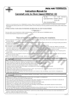
The Partia1 Revision
for FA-200 Service Manual and Parts Catalogue
(Part
Since FA-200MAIN
2)
WHEEL ASSY was added, FA-200 Service Manual and Parts Catalogue
has been modified, so we will inform you of the modified contents.
We attached Service Manual and Parts Catalogue separately. Please use them according
to the following attached documents.
1.Service
(1)
(2)
2.Parts
Attached Service Manua1 Page
Manua1 N0.
200-010003A
200-010013
●
●
●
●
麹
菌
●
■
‐
個
‐
●
●
●
PAGE
3
PAGE
7
6
心
10
(9-6A,
9-7、
9-8)
●
PAGE
H
12
(4・
PAGE
13
14
(4・
II
00
●
●
9。︲9。
︲
恥刳YOUNANICHOME,UTSUNOMIYATOCHIGIJAPAN
320-8564 TEL 028(684)7253,FAX028(684)7260
●
●
44
AEROSPACECOMPANY
●
9。
●
●菌麹菌
1
●
9。
200-0100H
9-8)
1
︻ 一
200-010001B
(2)
9-7、
Attached Parts Catalogue Page
Cata訪gue No.
(1)
(9-6A,
SERviCE
NEWS 200-007
PAGE
1
0F
14
[BLANK]
SERVICE
PAGE
2
NEWS 200-007
0F
14
尚尚◎四グ
・FUJI
FA-200
SERVICE
MANUAL
account.
(5)lnstall and tighten the wheel attaching bolts as fbllows
a.9532522
whee1
Position countersunk
washer under bolt with countersink toward bolt head. Then insert the bolt with
bolt head inboard.
lnstaU nut and one plain washer on the bolt.
First,tighten three nuts to 30 in-lbs torque. Next, tighten them to 60 in-lbs torque,andthen,tighten
them to 83 in-1bs torque.
b.9532522-1 wheel
After applying antiseize compound
(MIL-T-5544)tothreadpartofbolt,contact
washer,self-1ocking nut, countersunk
same proceduTes as 9532522
washer and plain washer, instan and tighten the nut by the
instamng
42FLW-428
−
nut on 9532522 wheel, referto
proper bolt tightening procedure fbr 9532522-1
ISSUED : SEPTE囲ER
and
wheel.
−CAUTION
When
area ofbo比head
whee1.
9−6A
1987
SERvlCE
NEWS 200・007
PAGE
3 0F
14
[BLANK]
sEnvlcE
PAGE
NEws 200・007
4
0F
14
`詞藻弾奏
FtJJI Fか200
SERVICE
MANUAL
(6)Enminatethewrinklesofthetubebyinflatinganddenatingit.Aftersettingittothetirerim,
innate the tireto the specined alrpressure.
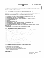
9・3-10 DISASSEMBLING
OF MAIN
GEAR
SHOCK
STRUT
(SEE
The11〕nowing procedures areapplicable to the shock struts removed
landing gear struct cover and fairing to be removed
FIG. 9・5)
from the airplane. (The wheel,
per applicable instructions.)
(1)With the airvalve cap 削l removed,discharge aircompletelyfiom thecore (12).
(2)Remove the airvalve body (13)from the plug {16}.
(3)Withthesnapr㎞g
05〕removed,relnovethe stopper (19),plugand“0'jring (17).
(4)Pun out the orificet ube (18).
(5)Drainoil.
(6)Remove theix3rqueknee {28}.
(7)Wlth the bolt {32}removed,disconnect the piston (25)liom the socket (26).
(8)PuU out the pistonfyom the upper end ofthe cylinder.
(9)Withthesnap rhlg (24)ofthe cyhder skirt8ectionren!oved,remove the adapteH23)and
scraperring(22).
(10)Remove the“○'j
ring C201andoilpad{33}をom inside the cylinder.
9・3・11 ASSEMBLING
OF I【AIN GEAR
SHOCK
STRUT
(1)After deaning allparts properly, check them fbry乙earand damage. Replace defbctive parts.
Replace “O" rings withnelvones.
(2)lnstan “O" ring and oilpad inside the cylinder.
(3)lnstan
the scraper ring and adapter on the cylinder skirt with thesnap
ring・
(4)lnsert the piston fyom the upper side of the cynnder.
(5)lnstan
the piston and socket with bolts.T址hten the boks to 270 ∼300 in-lb.
(6)lnstan
the torque knee.
(7)lnstan
the ori丘cetube.
(8)Lubricate
the strutinaccordancewithpara.3-2-2.
(9)lnstall the“O" ring, stopperand
(10)lnstan
(n)Charge
9・4 NOSE
plug with the snap ring・
the“○"ring and valve body on the plug・
airinaccordance
LANDING
GEAR
with para. 3-2-12 and install the valve cap・
(SEE
FIG. 9・6)
9-4-1 REMOVALANDINSTALLATIONOFNOSELANDINGGEAR
(1)Remove也eu卯erengine
(2)Lift
a.1ifting the fbrward
b.jacking
lss屈D
cownng・
the nose gear ofr the ground
fuselage using
either by
the engine
hoist ring, o『
up the airplane per para.2-2.
: sllTEnn
1987
9−7
SERVICE
NEWS 200,007
PAGE
5 0F
14
FUj】FA-2no
SERVICE
MANUAL
犬ベド゛グ
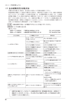
l.
Cap
valve core
Body
4. “O”ring
Snap ring
Plug
“O”ring
Stopper
orificetude
“OI’ring
on pad
Cylinde7
Adapter
Scraper ring
Snap ring
Piston
Torquelik
Torque link
Pin
phl
C扨ter pir1
Bolt
Spacer
24.Washer
25.Nut
26.Bushing
27.Socket
28.BOlt
29.Spacer
2.
3.
心 旧
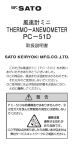
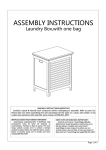
FIG 9-5 MAIN
9-8
SERVICE
NEWS 200-007
PAGE
6
0F
14
GEAR
SHOCK
STRUT
AND
TORQUE
LINK
ISSUED:APRIL1972
`四瘤四グ
FUJI
FA-200
SERvlCE
MANUAL
account.
(5)lnstaU and tighten the wheel attaching bolts as 訟lows:
a.9532522
wheel
Position countersunk washer under bolt with countersink toward bolt head. Then insert the bolt with
bolt head inboard.
lnstan nut and one plain washer on the bolt.
First,tightenthree nuts to 30 in-lbs torque,Next, tighten them to 60 in-lbs torque,andthen,tighten
them to 83 in-lbs torque.
b.9532522-1
whee1
Afler applying antiseize compound
(MIL-T-5544)to
washer,self-1ocking nut,countersunk
thread part ofbolt,contactareaofbolt
head and
washer and plain washer, installand tighten the nut by the
same procedul・es as 9532522 wheel.
一CAUTION
When
installing 42FLW-428
−
nut on 9532522
wheel, referto
proper bolt tightening procedure fbr 9532522-1
wheel.
9−6A
ISSIBD : SEF7E掴皿1987
SERVICE
NEWS 200-007
PAGE
7
0F
14
[BLANK]
SERvtCENEWS
PAGE
8
0F
200・007
14
`鯛ヨドダ
RJJI
Fλ-200
SERVICE
MANUAL
(6)Eliminatethewrinklesofthetubebyinnatinganddenatingit.Aftersettingittothetirerim,
innate the tireto the speci丘edairpressure.
9-3-10 DISASSEMBLING
OF MAIN
GRAR
The fbnowing procedures areappUcable
SHOCK
STRUT
(SEE
to the shock struts removed
landing gear struct cover and fairingto berenloved
FIG. 9-5)
from the airplane. (The wheel,
per applicable instructions.)
(1)With the airvalve cap (H)removed,discharge aircompletely肋mthecore (12).
(2)Remove the air valvebody (13)fyom the plug (16).
(3)Withthesnap ring (15)removed,relnovethe stopper (19),plugand“O" ring (17).
(4)Pun out the orificet ube (18).
(5)Drainoil.
(6)Remove the torque knee (28).
(7)With the bolt (32)removed,disconnect the piston (25)fyom the socket (26).
(8)Pun out the pistonfrom the upper end ofthe cylinder.
(9)Withthesnap ring (24)ofthecynnderskirtsectionremoved,remove the adapter (23)and
scraperring(22).
(10)Remove the“O" ring (20)andoilpad(33)from inside the cylinder.
9-3-11 ASSEMBLING
(1)After deaning
OF MAIN
GEAR
SHOCK
STRUT
allparts properly, check them for wear and damage. Replace defbctive parts.
Replace “O" rings with new ones.
(2)lnsta11“O" ring and on pad inside the cylinder.
(3)lnstall the scraper ring and adapter on the cylinder skirt with the snap ring・
(4)lnsert the piston from the upper side of the cylinder.
(5)lnstall the pistonand
socket with bolts.Tighten bolts to 30 to 40 in-lbs.
(6)lnstall the torque knee.
(7)lnstan the ori丘cetube.
(8)Lubricate
the strut in accordance with para. 3-2-2.
(9)lnstall the“O" ring, stopper and plug with the snap ring,
(10)lnstan the“O≒ing and valve body on the plug・
(11)Charge
9・4 NOSE
airin accordance with para, 3-2-12 and install the valve cap・
LANDING
9-4-1 REMOVALAND
(1)Remove
(2)Lift
the upper
GEAR
(SEE FIG. 9-6)
INSTALLATION
engine
up the airplane
LANDING
GEAR
cowling・
the nose gear o江the ground
a.lifting the f1)rward fuselage using
b.」acking
OF NOSE
either by
the engine
hoist ring, o「
per para.2-2.
9−7
1SSUED: SEPTEMBER1987
SERviCE
PAGE
9
NEWS 200-007
0F
14
FUjl
FA-200
SERVJCE
MAN U A L
一一一一一一
一 溥゛ぢ
 ̄ぶ
1.
2.
3,
4.
Cap
valve core
Body
“O”ring
Snap ring
Plug
“o”ring
Stopper
orificetude
“O’lring
on pad
Cylinde?
Adapter
Scraper ring
Snap ring
Piston
Torquelik
Torque link
Cotter
Bolt
Spacer
Wasller
Nut
26.Bushing
27.Socket
28.BOlt
29.Spacer
心 哨
FIG 9・5 MAIN
9-8
SERVICE
、E吸GE
NEWS 200-007
10
0F
14
GEAR
SHOCK
STRUTAND
TORQUE
LINK
pin
ミ
㎜
|
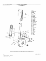
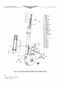
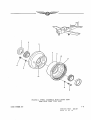
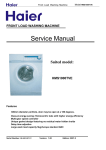
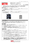
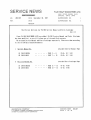
14. W11EEL
(USE
ISS狸D:NOVE圓ER
ASSEMBLY.MAIN
WITH
TUBE
ITyPE
LADING
jy
軋レ
FIGURE
GEAR
TIRE3
4−19
1970
SERviCE
XEWS 200-007
PAGE
n
oF
14
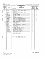
SECTION
IV
LANDING
GEAR
WREEL
GROUP
ASSEMBL¥,MAIN
FIG&
PART
INDEX
DESCRIPTION
1234567
14-
USABLE
PER
ON
ASS゛Y
CODE
9532522
WHEEL
9532522-1
WHEEL
ASSYI MAIN
LANDING GEAR・・・……;…………
A B
|
1
(U.S.G.Y)
3
|
5
一
6
・・・‥‥‥‥‥‥‥‥
・NUT,SELF
LOCKING
42FLW-428
MS20002-4
・NUT,SELF
LO・
・WASHER………………………………
●油奉●●●●
NAS144-23
・BOLT…………・・・・・一一・・・一一
*MS20002C4
*9525391
・WASHER,COUNTERSUNK
・PLATE,DATA
ADHESIVE
INBOARD‥‥‥‥‥‥‥‥‥‥‥
*5008252
・PLATE,DATA
ADHESIVE
INBOARD‥‥‥‥‥‥‥‥‥‥‥
*9525392
DATA
●●●●●●●
・・・‥‥‥
●あ●●●灸4
ADHESIVE
−?
−8
13830
‥CUP,BEARING・・・……
−9
MS20426DD6-6
9525059
・一一RIVET‥‥‥‥‥‥‥‥‥‥‥‥
●一●●●●●
・・・・・・・・・−・・,
CYMQ
・‘CLIP.DISC
●噛●a●●●●●●●●●●●●●●●■●●■●■■■■■■■‐●■■■■■●j
一¶●●●●●
13830
*AN504-8R8
・・CUP,BEARING・・・‥‥‥‥‥‥‥‥‥‥
*9524491
一一CLIP,VALVE・・−・・・・・・・…−−・・−・−……………..…−.…
*9524877
・・・・・・・・…・……・・・
KITI WHEEL (ORDER
11
9524318
-12
・・SCREW
11
SUBASSEMBLY,0UTBOARD…………………
-11
'WHEEL
BALANCE
1
WEIGHT
●●●●●●●
SEPARATELY)
・CLIP,BALANCE WEIGHT DISC・・・………………………
*AN520-10-1C
・SCREWI
*NAS6?9A3W
・NUT,BALANCE
・DISC,BALANCE
BALANCE
B・
4-20
SERVICE
NEWS 200・007
1脇GE 12 0F 14
j●●●I●●・●●■・●・■●・・・・■・●・■・・・・
WEIG]
●●●●●●●●●
2
WEIGI
ILLUSTRATED
A………………FOR
|
WEIGI
BALANCE・・
CQ C4
・WEIGHT,LEAD
ち`り1
*9524876
*9524875
*9S24858
*NOT
11
OUTBOARD
………………
‘PLATEI
ADHESIVE
OUTBOARD‥‥‥‥‥‥‥‥‥
‘PLATE,DATA
SUBASSEMBLY,INBOARD‥‥‥‥‥‥‥‥‥‥‥‥‥
’WHEEL
*5008253
9524201
-10
・・・…・
ABAB
一
・CONE,BEARING
22珂H-428
Qり1111
4
GEAR…………………
・・・・−・一一一一一一一一・
Q︶Qり
−
9524218
13889
ASSYI MAIN LANDING
BEARING
AB
ー
2
・SEAL,・
CyMQ
ミ
1
Cg N
−
GIAR
UNITS
NO.
NO.
LANDING
FOR
9532522
9532522-1
WHEEL
WHEEL
ASSY
ASSY
ISSIEI
: SEFTE
・露i987
屋
●
犬愉か
|
2
||
∧
4
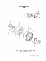
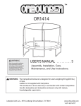
14. WHEEL
(USE
ASSEMBLY.MAIN
WITHTUaE
TYPE
LADING
‰ド
軋レ
FIGURE
GEAR
TIRE)
4−19
SERvtCE
PAGE
XEWS 200-007
13
0F
14
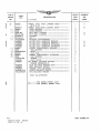
UNITS
‘FIG&
PART
INDEX
DESCRIPTION
ON
ASS゛Y
CODE
NO.
NO.
1234567
9532522
14-
WHEEL
ASSY, MAIN LANDING GEAR………;…………
A B
|
1
(U.S.G.Y)
ー
2
3
9532522-1
WHEEL
9524218
13S89
・SEAL、BEARING・・・‥‥‥‥‥‥‥‥‥‥‥‥‥‥‥‥‥‥‥
221ミH-428
4
5
NAS144-23
=
6
*MS20002C4
*95S391
*9525392
・NUT,SELF
LOCKING ・・・・・・一一,………………………………
・WASHER・・・…………
●■●●■・●■■●■●●・●●●・I●●
・BOLT・・・・…・・・・・・・・・・・・−・・・・
・WASHER,COUNTERSUNK…………………………………
・PLATE,DATA
‘PLATE,DATA
・PLATE,DATA
ADHESIVE
INBOARD
・・・‥‥‥‥‥‥‥‥‥
ADHESIVE
INBOARD
・・・・・・・・・・‥‥‥‥‥‥
ADHESIVE OUTBOARD
ADHESIVE
OUTBOARD
・・・・‥‥‥‥‥‥‥
‘PLATE,DATA
SUBASSEMBLY,INB£)ARD・・・‥‥‥‥‥‥‥‥‥‥‥
‘WHEEL
−9
MS20426DD6-6
・・・RIVET…・・・・・・・・・・−・・……・
-10
9525059
9524318
・・CLIP,DISC‥‥‥‥
13830
*AN504-8R8
‥CUP,BEARING………………………………………………
*9524491
・‘CLIP,VALVE・・・……・
-11
-12
*9524877
‥CUP,BEARING・‥‥‥‥
・WHEEL
一一SCREW
・・・・・・・・・・・・・・・・・.j・…・.=…・・・・・・……..................…...
KITj WHEEL・
憚・●●●●●
BALANCE
WEIGHT一一・s・・・・・・・・…・・・・…・・…・・・
SEPARATELY)
・CLIP,BALANCE
WEIGHT
・DISC,BALANCE
WEIGI
*AN520-10-10
*NAS679A3W
・SCREW、BALANCE
DISC…………………………
・WEIGHT,LEADBALANCE…………………………………
WEIGHT・
4-20
SERVICE
1戮GE
2
ILLUSTRATED
A・…‥・‥・り・・・FOR9 532522 WHEEL
B……………FOR
9532522-I WHEEL
|
●●●●●●●
・NUT,BALANCEWEIGHT…………………………………
*NOT
NCM
*9524876
*9524875
*9524858
1
Q︸1
(ORDER
●●●●●參摯
SUBASSEMBLY,0UTBOARD‥‥‥‥‥‥‥‥‥‥‥
11
9524201
13830
CyM9 11
−8
11
15008253
−7
‘NUT,SELF
●●S・●・●
・・・‥‥‥・‥‥‥‥‥‥‥‥‥‥‥
AB
*5008252
●・I●・●●・・●I●●・●・■●●●●●■●●・●●■●●■●●■●●■・・・■I
LOCKING
AB
∼
・CONE,BEARING・−・・
GEAR………,……………
CYMQ︷`り1111
42FLW-428
MS20002-4
|
ASSY,MAIN LANDING
AB
ミ
1
MQUUQQ
一
USABLE
PER
ASSY
ASSY
ISSⅢD : SEMllBER
14
NEWS 200-007
0F
14
1987