1
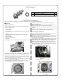
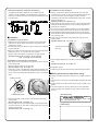
Instruction Manual for
Camshaft only for Bore Upped INNOVA 125
CO
:01−08−0004
Applicable Models :HONDA ANF125
Item No.
Innova 125
※but excluding PGM-FI
・Thank you for purchasing one of our TAKEGAWA’s products. Please strictly follow the following instructions in installing and using the products.
・Before fitting the products, please be sure to check the contents of the kit. Should you have any questions about the products, please kindly contact
your dealer.
◎ Please note that, in some cases, the illustrations and photos may vary from the actual hardware.
∼ Features ∼
The cam profile is cut and machined by a CNC camshaft grinding machine so it best suits our TAKEGAWA’s bore up.
A standard decompression equipment can be installed.
Read all instructions first before starting the installation.
PY
◎ We do not take any responsibility for any accident or damage whatsoever arising from the use of the kit not in conformity with the instructions in this
Instruction Manual.
◎ We shall be held free from any responsibility or compensation whatsoever for any glitch in the parts other than ours if the glitch takes place after the
installation and use of the kit.
◎ Fix this product correctly, referring to a genuine service manual for an above-mentioned suitable model.
◎ For installation, please prepare suitable tools and work with reference to the installation instructions with enough care. Besides, this instruction manual and a genuine service manual are prepared with those in mind who have basic skills and knowledge. Therefore, we recommend those who
have never installed the parts or those who do not have sufficient tools to ask a technically-reliable specialist shop for the work.
◎ The installation of this product requires processing to the cylinder head. Therefore, process the cylinder head referring to the “Processing of the Cylinder Head.”
◎ Please note that this kit is designed for exclusive use in the compatible models and frame numbers as mentioned above only and that it cannot be
mounted on any other models.
◎ Bolts, nuts, and packings will be reused. However, be sure to replace worn-down or severely-damaged ones with new ones.
The following show the envisioned possibility of injuries to human bodies and property damage as a result of disregarding the
CAUTION following cautions.
・Work only when the engine and muffler are cool. (Otherwise, you will get burned.)
・Do the installation with right tools. (Otherwise, breakage of parts or injuries to you may take place.)
・Always use a torque wrench to screw bolts and nuts tight and securely to the specified torque.
(Otherwise, these parts may get damaged or fall off, resulting in accidents.)
・As some products and frames have sharp edges or protruding portions, please work with your hands protected.
(Otherwise, you will suffer injuries.)
・Before riding, always check every hardware like screws for slack. If you find slack ones, screw them securely up to the specified torque.
(Otherwise, improper tightening may cause parts to come off.)
・Always use new gaskets and packings. And check those parts, to be reused, for wear and damage. If you find worn or damaged parts, replace them with new ones.
The following show the envisioned possibility of human death or serious injuries to human bodies as a result of disregarding the
WARNING following warnings.
・Always start the engine in a well-ventilated place, and do not turn on the engine in an airtight place.
(Otherwise, you will suffer from carbon monoxide poisoning.)
・When you notice something abnormal with your motorcycle while riding, immediately stop riding and park your motorcycle in a safe place to check what has gone wrong. (Otherwise, the malfunction could lead to accidents.)
・Before doing work, make sure your motorcycle is secure on level ground for safety’s sake.
(Otherwise, your motorcycle could overturn and injure you while you are working.)
・Check or carry out maintenance of your motorcycle correctly according to the procedures in the instruction manual or service manual.
(Improper checking or maintenance could lead to accidents.)
・If you find damaged parts when checking and performing maintenance of your motorcycle, do not use these parts any longer, and replace them
with new ones. (The continued use of these damaged parts as they are could lead to accidents.)
◎ Please be informed that, mainly because of improvement in performance, design changes, and cost increase, the product specifications and prices are subject to change without prior notice.
◎ This manual should be retained for future reference.
-1-
Mar./03/’
09
∼ Kit Contents ∼
1
CO
2
No.
Part Name
Qty
1
CAMSHAFT COMP.
1
2
BEARING、RADIAL BALL、6902Z
1
∼ Installation Procedures ∼
※ Secure your bike on level, safe ground. Do the work hereafter only when the engine and muffler are cool.
◇ Holding the flywheel, unscrew two bolts on the camsprocket to
remove the camsprocket.
◇Remove a sealing screw and O-ring on the camchain tensioner lifter. And turn the shaft all the way clockwise to lock the lifter.
◇ Detach the stopper plate from the cylinder head in order to remove the
camshaft.
◇ Loosen four head nuts and two head bolts diagonally in a few steps to
remove them. And remove four washers and cylinder head.
●Removal
①Removal of hardware:
◇ Referring to a genuine service manual, remove the following parts: a. Cover, main pipe, upper
b. Cover, center
c. Cover, front top
PY
d. Cover, under
e. Left leg shield cover, left leg shield inner cover, left main pipe side cover
f. Right left shield cover, right leg shield inner cover, and right main
pipe side cover
g. Exhaust muffler
h. Intake manifold, carburetor
i. Spark plug
◇ Disconnect the tube running from an air suction valve to air feed pipe.
○Processing of cylinder head:
・As the cam top and cylinder head inner wall interfere with each other, process the interfering potions on the cylinder head.
Remove components like a valve before starting processing. And after
the processing, clean the cylinder head with water, and remove the chips with an air blow apparatus.
・The Photograph 1 shows the part to be processed when seen from the
cylinder head side cover, and the photograph 2 shows the same part when seen from the exhaust side of the tappet adjusting hole cover. However, the part to be processed and the extent of processing vary among cylinder heads. Therefore, before using the camshaft, recheck
carefully whether there is no more interference with the cam top and inner wall of the cylinder head.
Exhaust cam interrence part B
○○
②Removal of a camsprocket, camshaft and cylinder head:
◇ Remove a tappet adjusting hole cover on intake and exhaust sides.
◇ Remove an A.C. generator cap and O-ring of the left-side crankcase
cover, and a crankshaft hole cap and O-ring.
◇ Remove a bolt and sealing washer on the right side of a cylinder head
Intake cam interrence part
Photograph1
to remove a left cylinder head side cover.
◇ Turn the flywheel counterclockwise, and align the “O” mark on the camsprocket with the notch on the cylinder head.
Cam setting plunger
Exhaust cam interrence part A
Exhaust cam interrence part B
Photograph2
-2-
Mar./03/’
09
○About decompression equipment and bearing
③Adjustment of valve clearance:
・A standard decompression equipment can be installed onto this
camshaft. For easy installation of the decompression equipment, a
bearing on one side is not fixed. So, before using the camshaft, be sure
to fix the bearing.
◇Set the “T” mark on the flywheel to mesh with the notch on the left crankcase cover, and the “O” mark on the camsprocket with the notch
on the cylinder head. Adjust the adjusting screw so the valve
clearances on the intake and exhaust sides are 0.05mm both, and then
tighten the adjusting nut.
Specified torque: 9 N・m (0.9 kgf・m)
CO
※ When setting the marks as above, never turn the camshaft clockwise.
Otherwise, the decompressor cam will work, making it impossible to adjust the valve clearance.
※ If you have turned the camshaft clockwise, turn it counterclockwise once more. And align the marks, and then adjust the valve clearance.
◇ Fix the gaskets and left-side cylinder-head side cover to the cylinder head, and put the bolt and sealing washer into the cylinder head from its
right, and tighten them.
●Installation
①Installation of cylinder head:
◇ Degrease the mating surfaces of the cylinder and the cylinder head with thinner or the like. Attach two dowel pins and cylinder head
gaskets to the cylinder.
◇ Fix the cylinder head, and tighten for now four head nuts, four washers
and two head bolts.
★ Attach the copper washers at the lower left of the cylinder head when
viewed from you (or, on your lower left of the cylinder).
◇ Tighten up the nuts diagonally in a few steps, and then the bolts.
Specified torque: 20 N・m (2.2 kgf・m) for head nut,
12 N・m (1.2 kgf・m) for head bolt
②Installation of camshaft and camsprocket:
◇ Check that “T” mark on the flywheel is meshing with the alignment mark
on the crankcase cover. And attach the camsprocket to the camchain so
the “O” mark on the camsprocket meshes with the notch on the cylinder
head.
“O” MARK / CUT-OUT
Left-side cylinder-head
side cover
PY
◇Apply engine oil to the camshaft cam top and bearing, and then fix them
to the cylinder head.
◇ Attach the stopper plate to the cylinder head.
Specified torque: 12 N・m (1.2 kgf・m)
“T” MARK / CUT-OUT
★ At this point, set the left-side cylinder-head side cover at the anti rotation stopper.
Specified torque: 12 N・m (1.2 kgf・m)
Tab and stopper
◇ Attach a tappet adjusting hole cover each on the intake and exhaust sides.
Specified torque 12 N・m (1.2 kgf・m)
④ Installation of parts:
◇ Referring to the genuine service manual, install all the removed parts.
●Safety precautions to take before riding:
◇ Always check every hardware for slack in them including screws and
nuts.
◇ Start and warm up the engine in a well-ventilated safe place with great
care.
◇Check that there is no unusual noise from the engine or oil leak in every
gasket.
◇ Turn off the engine first, and only after the engine has cooled down, check once again every hardware for slack in them including screws and nuts.
Manufactured by
L.CRANKCASE COVER
Co.,Ltd.
◇ Fit the camsprocket into the dowel pin of the camshaft, and fix them 3-5-16 Nishikiorihigashi Tondabayashi Osaka Japan
URL : http://www.takegawa.co.jp
with two bolts.
Specified torque: 9 N・m (0.9 kgf・m)
◇ Turn the shaft of the camchain tensioner lifter counterclockwise a little,
and unlock the push rod. Then attach a sealing screw and O-ring to the
camchain tensioner lifter.
Specified torque: 4 N・m (0.4 kgf・m)
Distributed by
-3-
Mar./03/’
09