1
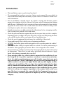
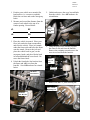
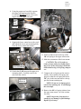
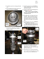
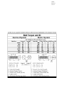
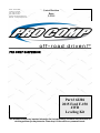
62206 Revised 2.23.15 400 W. Artesia Blvd. Compton, CA 90220 Fax: (310) 747-3912 Ph: 1-800-776-0767 E-Mail: [email protected] Website: www.procompusa.com Latest Revision Date: 2.23.15 PRO COMP SUSPENSION Part # 62206 2015 Ford F-150 4WD Leveling Kit This document contains very important information that includes warranty information and instructions for resolving problems you may encounter. Please keep it in the vehicle as a permanent record. 62206 Revised 2.23.15 Part # Description Qty. 61-40161 UPPER STRUT SPACER 2 61-40162 PRELOAD SPACER 2 90-6638m HARDWARE PACK 10MM - 1.5 10.9 METRIC FLANGE NUTS 1 6 62206 Revised 2.23.15 Introduction: This installation requires a professional mechanic! We recommend that you have access to a factory service manual for your vehicle to assist in the disassembly and reassembly of your vehicle. It contains a wealth of detailed information. Prior to installation, carefully inspect the vehicle’s steering and driveline systems paying close attention to the tie rod ends, ball joints, wheel bearing preload, pitman and idler arm. Additionally, check steering-to-frame and suspension-to-frame attaching points for stress cracks. The overall vehicle must be in excellent working condition. Repair or replace all worn or damaged parts! Read the instructions carefully and study the illustrations before attempting installation! You may save yourself a lot of extra work. Check the parts and hardware against the parts list to assure that your kit is complete. Separating parts according to the areas where they will be used and placing the hardware with the brackets before you begin will save installation time. Check the special equipment list and ensure the availability of these tools. Secure and properly block vehicle prior to beginning installation. ALWAYS wear safety glasses when using power tools or working under the vehicle! Use caution when cutting is required under the vehicle. The factory undercoating is flammable. Take appropriate precautions. Have a fire extinguisher close at hand. Foot pound torque readings are listed on the Torque Specifications chart at the end of the instructions. These are to be used unless specifically directed otherwise. Apply thread lock retaining compound where specified. Please note that while every effort is made to ensure that the installation of your Pro Comp lift kit is a positive experience, variations in construction and assembly in the vehicle manufacturing process will virtually ensure that some parts may seem difficult to install. Additionally, the current trend in manufacturing of vehicles results in a frame that is highly flexible and may shift slightly on disassembly prior to installation. The use of pry bars and tapered punches for alignment is considered normal and usually does not indicate a faulty product. However, if you are uncertain about some aspect of the installation process, please feel free to call our tech support department at the number listed on the cover page. We do not recommend that you modify the Pro Comp parts in any way as this will void any warranty expressed or implied by the Pro Comp Suspension company. 62206 Revised 2.23.15 1. Position your vehicle on a smooth, flat, hard surface (i.e. concrete or asphalt). Block the rear tires and set the emergency brake. 5. Unbolt and remove the sway bar end links from the vehicle. Save OE hardware for reinstallation. 2. Measure and record the distance from the center of each wheel to the top of its fender opening. Record below. LF: RF: LR: RR: 3. Place the vehicle in neutral. Place your floor jack under the front crossmember and raise the vehicle. Place jack stands under the frame rails and lower the frame onto the stands. Remove the jack and place the vehicle back in gear, set the emergency brake, and place blocks both in front and behind the rear wheels. Remove the front wheels 4. Unbolt the front brake line bracket from the frame and ABS wire from the knuckle. Save OE hardware for reinstallation. Sway Bar End Link 6. Using the proper tool carefully separate the outer tie rod end from the knuckle. Remove the retaining nut and remove the outer tie rod end from the knuckle. Outer Tie rod end Knuckle OE Brake Line Bracket 7. Remove the OE CV joint retaining nut. OE CV Joint Retaining Nut OE Brake Line Bracket 62206 Revised 2.23.15 8. Using the proper tool carefully separate the upper ball joint from the knuckle. Loosen but DO NOT remove the retaining nut from the upper ball joint. Upper Ball Joint Knuckle 9. Support the lower control arm with a jack and unbolt the lower strut mounting bolts from the lower control arm mount. OE Strut Removed Lower A-arm 11. Scribe an index mark on the top of the OE coil spring to the upper strut mount. 12. Mark the orientation of the lower mount. Lower Strut Mount 10. Unbolt the (3) OE nuts on the upper strut mounting studs. Carefully remove the strut from the vehicle. Upper Strut Mount Nut CAUTION: The coil is under extreme pressure and severe bodily injury may occur if the coil spring is disassembled without using a coil spring compressor. 13. Compress the coil spring on the strut assembly with a suitable coil spring compressor so that the coil spring has about 3/8” play in the strut and remove the upper strut mount retaining nut. NOTE: Do not use an impact gun to remove the retaining nut. It will damage the strut shaft. 14. Remove the OE coil spring isolator from the upper strut mount. Save the isolator for reuse. NOTE: Inspect the front shock assembly for any damage or fluid leakage. Replace if necessary. 62206 Revised 2.23.15 15. Carefully remove the coil spring from the strut. 16. Insert the OE spring isolator into the supplied preload spacer (61-40148). 18. Install the preload spacer (61-40162) assembly and OE upper strut mount using the OE retaining nut. 19. Torque the upper strut mounting plate retaining nut to 20 ft./lbs. NOTE: Failure to properly tighten the upper strut mounting nut will result in suspension noise. 20. Decompress the coil spring on the strut assembly. Make sure that the spring is seated correctly into the strut assembly and aligned with the previously scribed index mark on the upper strut mounting plate. Preload Spacer 61-40148 OE Spring Isolator 21. Install the upper strut spacer (61-40161) onto the OE studs on the strut. NOTE: Because this kit retains the use of the OE studs the vehicle can easily be returned to it’s stock form. 17. Reinstall the compressed coil spring onto the strut assembly using the reference marks as a guide. Strut Spacer 61-40149 Preload Spacer 61-40148 Strut Assembly OE Strut Assembly 22. Install the strut assembly into the strut tower and secure using the supplied 10mm flange nuts. Leave the bolts hand tight only at this point. 23. Reinstall the lower strut mount onto the lower control arm mount and secure using the previously removed OE hardware. 62206 Revised 2.23.15 bar. Torque according to manufacturers specifications. Strut Tower Strut Assembly 29. Reinstall the front brake line bracket to the frame and knuckle using the previously removed OE hardware. 30. Repeat the steps 5 Through 29 On the remaining side of the vehicle. 31. Install the front tires/wheels and lower the vehicle onto the ground. 32. Torque all bolts to factory specifications. Re-torque all bolts after 500 miles. IMPORTANT! BE SURE TO BRING THE VEHICLE IMMEDIATELY TO A REPUTABLE ALIGNMENT SHOP TO BE ALIGNED! 24. Torque the upper and lower strut mounting hardware to manufacturers specifications. 25. Slide the CV joint into the knuckle and reinstall the knuckle to the upper ball joint. Torque the upper ball joint nut to manufacturers specifications. NOTE: It may be necessary to pry the upper control arm down, using a pry bar inserted into the coil spring, to force the ball joint stem into the spindle. 26. Reinstall the OE CV joint retaining nut. Torque according to manufacturer’s specifications. NOTE: Be sure the CV joint is properly installed or damage to the locking hub may occur. 27. Reinstall the outer tie rod end to the knuckle. Torque the outer tie rod end nut to manufacturers specifications. 28. Reinstall the sway bar end link to the lower control arm and secure top the sway Finished Assembly 62206 Revised 2.23.15 62206 Revised 2.23.15 Revision Page: 62206 Revised 2.23.15 The PRO COMP PROMISE WARRANTY At Pro Comp, we know you have many choices when selecting products to personalize your vehicle. You should demand nothing but the highest quality available and have total confidence that the products you selected are the best in the industry. It is for these reasons that Pro Comp Suspension products are backed by the best warranty in the industry...the Pro Comp Promise! Pro Comp promises that its products will last a lifetime or we will replace it free of charge. It’s that simple! Because of our commitment to quality and manufacturing excellence, we are able to stand behind our products. FOREVER. It is Pro Comp’s Promise that if one of our suspension products breaks not due to misuse, neglect or vandalism, we will replace it. Whether you are the original purchaser or not, you can be assured that we will make it right. The Pro Comp Promise covers all suspension products including shocks and steering stabilizers. Buy Pro Comp Suspension today and enjoy it for the rest of your life! That’s our Pro Comp Promise! Notice to Owner, Operator, Dealer and Installer: Vehicles that have been enhanced for off-road performance often have unique handling characteristics due to the higher center of gravity and larger tires. This vehicle may handle, react and stop differently than many passenger cars or unmodified vehicles, both on and off–road. You must drive your vehicle safely! Extreme care should always be taken to prevent vehicle rollover or loss of control, which can result in serious injury or even death. Always avoid sudden sharp turns or abrupt maneuvers and allow more time and distance for braking! Pro Comp reminds you to fasten your seat belts at all times and reduce speed! We will gladly answer any questions concerning the design, function, maintenance and correct use of our products. Please make sure that the Dealer / Installer explains and delivers all warning notices, warranty forms and instruction sheets included with Pro Comp product. Warranty and Return Policy: Pro Comp warranties its full line of products to be free from defects in workmanship and materials for the life of the product. Pro Comp’s obligation under this warranty is limited to repair or replacement, at Pro Comp’s option, of the defective product. Any and all costs of removal, installation, freight or incidental or consequential damages are expressly excluded from this warranty. Pro Comp is not responsible for damages and / or warranty of other vehicle parts related or non-related to the installation of Pro Comp product. A consumer who makes the decision to modify his vehicle with aftermarket components of any kind will assume all risk and responsibility for potential damages incurred as a result of their chosen modifications. Warranty coverage does not include consumer opinions regarding ride comfort, fitment and design. Warranty claims can be made directly with Pro Comp or at any factory authorized Pro Comp dealer. IMPORTANT! To validate the warranty on this purchase please be sure to mail in the warranty card. Claims not covered under warranty * Parts subject to normal wear; this includes bushings, bump stops, ball joints, tie rod ends and heim joints. * Finish after 90 days. * Damage caused as a result of not following recommendations or requirements called out in the installation manuals. Pro Comp MX Series coil-over shocks are considered a serviceable shock with a one-year warranty against leakage only. Rebuild service and replacement parts will be available and sold separately by Pro Comp. Contact Pro Comp for specific service charges. Pro Comp accepts no responsibility for any altered product, improper installation, lack of or improper maintenance or improper use of our products. E-Mail: [email protected] Website: www.procompusa.com Fax: (310) 747-3912 Ph: 1-800-776-0767 PLACE WARRANTY REGISTRATION NUMBER HERE: __________________