1
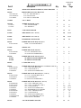
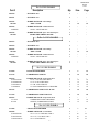
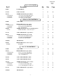
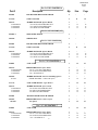
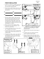
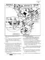
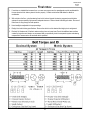
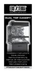
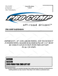
400 W. Artesia Blvd. Compton, CA 90220 Fax: (310) 747-3912 Ph: 1-800-776-0767 E-Mail: [email protected] Website: www.procompusa.com Latest Revision 7.22.2013 PRO COMP SUSPENSION Important: On some vehicles the driver’s side OE chassis wire harness that connects to the ABS wire may be shorter, from the factory, than others. If the line needs to be extended GM #19149296 (ACD#PT2232) can be installed into the chassis wire harness. IMPORTANT!: This system is designed for installation on both 4WD and 2WD models. For installation on 2WD models, disregard any and all steps involving the front differential & mounts, frame cutting, front driveshaft and C.V. shaft removal or installation. Part # K1154B/K1154BMX/ K1154BP/K1154BPS/K1154BPX 51014B/51014BMX/ 51014BP/51014BPS/51014BPX 6” 2014 & Up Chevrolet Silverado 4WD/2WD Lift Kit W/ Steel Knuckles Part # K1155B/K1155BMX/ K1155BP/K1155BPS/K1155BPX 51015B/51015BMX/ 51015BP/51015BPS/51015BPX 6” 2014 & Up Chevrolet Silverado 4WD/2WD Lift Kit W/Aluminum Knuckles This document contains very important information that includes warranty information and instructions for resolving problems you may encounter. Please keep it in the vehicle as a permanent record. 51014B/51015B Revised 7.22.13 Box 1 of 6-PN 51014B-1 Part # 90-3341 90-6299 70-0311001500 72-03100100512 73-03100030 Description REAR AXLE BRAKE LINE RELOCATION BRACKET HARDWARE PACK: Rear Brake Line 5/16” X 1” GR.5 HEX BOLT 5/16” NYLOCK NUT 5/16” SAE FLAT WASHER Qty. Illus. 1 - 1 2 2 4 - Page - 13-90087 9/16” U-BOLT 4 19 21 20-65302 13-30330 13-10423 HARDWARE PACK: U-Bolts 9/16” FLAT WASHER 9/16” HIGHNUT 1 8 8 19 19 21 21 95-501 5” REAR LIFT BLOCK 2 19 21 91-9480 DIFF MOUNT: Drvr– 4WD only 1 4,8 11,13 91-9483 DIFF MOUNT: Pass– 4WD only 1 5,8 11,13 91-2645 REAR BUMP STOP SPACER 2 20 22 90-6521 70-0311001800 HARDWARE PACK: Bump Stop Spacer 10mm-1.5 X 75mm HEX BOLT 1 2 - 91-9486 SKID PLATE 1 17 19 90-6939 70-0371001800 73-03700042 HARDWARE PACK: Skid Plate 3/8”-16 X 1 HEX BOLT GR. 8 3/8” SAE FLAT WASHER GR. 8 1 4 4 17 17 19 19 90-6940 90-9487 90-9488 HARDWARE PACK: Skid Plate Spacer OE SKID PLATE SPACER ROUND OE SKID PLATE SPACER 1 1 1 - - 90-4077 CV SPACER– 4WD only 2 11 14 90-6513 70-0311001800 72-031100816 73-04300034 HARDWARE PACK: Diff Mount Drvr Crossmember– 4WD only 1 5/16”-18 X 1 HEX BOLT GR. 4 5/16”-18 NYLOCK NUT . 4 5/16” SAE FLAT WASHER GR. 8 8 8 8 8 13 13 13 90-6514 70-0501751800 72-050100816 73-05000034 HARDWARE PACK: Diff Mount Drvr – 4WD only 1/2"-13 X 1 3/4" HEX BOLT GR. 8 1/2"-13 STOVER NUT 1/2" SAE FLAT WASHER GR. 8 1 2 2 4 6 6 6 12 12 12 90-6251 70-0564001800 70-0561751800 72-056100816 73-05600034 73-05600034 70-0563001800 72-056100816 73-05600034 71-100601251000 73-01008840 HARDWARE PACK: Differential – 4WD only 9/16”-12 X 4" HEX BOLT GR. 8 9/16”-12 X 1 3/4" HEX BOLT GR. 8 9/16”-12 STOVER NUT 9/16” SAE FLAT WASHER GR. 8 9/16” HARDENED FLAT WASHER 7/16”-14 X 3” HEX BOLT GR. 8 7/16”-14 STOVER NUT 7/16” SAE FLAT WASHER GR. 8 M10-1.5 X 60 HEX BOLT GR. 10.9 M10 USS FLAT WASHER 2 5/16” REAR SPRING SPACER 1 1 2 3 4 2 1 1 2 16 16 8 6 6,8 6,8 6,8 3 3 3 3 3 13 12 12,13 12,13 12,13 10 10 10 10 10 4 19 21 90-3957 - 51014B/51015B Revised 7.22.13 Box 2 of 6-PN 51014B-2 Part # Description Qty. Illus. Page 90-4570 KNUCKLE: Drvr 1 - - 90-4571 KNUCKLE: Pass 1 - - 90-6522 90-3240 HARDWARE PACK: Adel Clamps ADEL CLAMP 1 2 14 16 90-6439 .160FNFJZ HARDWARE PACK: Tie Rod Jam Nut 16mm-1.5 HEX JAM NUT 1 2 - - 90-6709 90-3950 HARDWARE PACK: Spare Tire Wheel Spacer SPARE TIRE WHEEL SPACER 1 2 - - Or Box 2 of 6-PN 51015B-2 90-4573 KNUCKLE: Drvr 1 - - 90-4574 KNUCKLE: Pass 1 - - 90-6522 90-3240 HARDWARE PACK: Adel Clamps ADEL CLAMP 1 2 14 16 90-6439 .160FNFJZ HARDWARE PACK: Tie Rod Jam Nut 16mm-1.5 HEX JAM NUT 1 2 - - 90-6709 90-3950 HARDWARE PACK: Spare Tire Wheel Spacer SPARE TIRE WHEEL SPACER 1 2 - - Box 3 of 6-PN 51014B-3 91-9490 REAR CROSSMEMBER 1 9 14 91-2319 COMPRESSION STRUTS 2 16 18 90-6234 70-0501251800 70-0504001800 72-050100816 73-05000034 HARDWARE PACK: Compression Strut 1/2" X 1 1/4" GR. 8 HEX BOLT 1/2" X 4" GR. 8 HEX BOLT 1/2" GR. 8 STOVER NUT 1/2" SAE HARDENED FLAT WASHER 1 2 4 4 1 16 16 16 16 18 18 18 18 90-3353 COMPRESSION STRUT NUT PLATE 2 16 18 91-1104 COMPRESSION STRUT MOUNT 2 16 18 90-6263 15-11148 90-2109 HARDWARE PACK: Compression Struts COMPRESSION STRUT BUSHING SLEEVE, COMPRESSION STRUT 1 8 4 16 16 18 18 Box 4 of 6-PN 51014B-4 91-3684 FRONT CROSSMEMBER 1 7 12 90-6284 70-0624501800 70-0625501800 72-06200100512 HARDWARE PACK: Crossmember 5/8"-11 x 4 1/2" HEX BOLT GR. 8 5/8"-11 X 5 1/2" BOLT GR. 8 5/8"-11 STOVER NUT 1 2 2 4 10 10 10 14 14 14 3 51014B/51015B Revised 7.22.13 Part # 73-06200030 Description 5/8" SAE FLAT WASHER Qty. Illus. Page 8 10 14 90-6498 71-100301251000 73-01010930 72-043100816 70-0432501800 72-043100816 73-04300034 HARDWARE PACK: Sway Bar Drop 10mm-1.5 X 30mm 10.9 HEX BOLT 10mm 10.9 FLAT WASHER 10mm STOVER NUT 7/16"-14 X 2 1/2" GR. 8 HEX BOLT 7/16"-14 STOVER NUT 7/16" SAE FLAT WASHER 1 4 8 4 4 4 8 15 15 15 15 15 17 17 17 17 17 91-3632 SWAY BAR DROP– Drvr 1 15 17 91-3635 SWAY BAR DROP– Pass 1 - 90-7734 90-7735 FRONT BRAKE LINE DROP BRACKET– Drvr FRONT BRAKE LINE DROP BRACKET– Pass 1 1 14 14 16 16 90-6517 70-0313751800 73-03100830 72-031100816 70-0251001800 73-02500830 72-025100816 -Not used-Not used-Not used-Not used- HARDWARE PACK: Brake Line Bracket 5/16" X 1" GR. 8 HEX BOLT 5/16" FLAT WASHER 5/16" GR. 8 STOVER NUT 1/4" X 1.0" GR. 8 HEX BOLT 1/4" FLAT WASHER 1/4" GR. 8 NYLOCK NUT #10-24 X 3/4" PHILLIPS MACHINE SCREW #10-24 PLATED NYLOCK WASHER #10 WASHERS #8 X 3/4" HEX BOLT (w/ loose "fender" washer on bolt) 1 2 4 2 4 8 4 4 4 8 8 14 14 14 14 14 14 14 14 14 14 16 16 16 16 16 16 16 16 16 16 90-6515 15-11148 90-2108 HARDWARE PACK: Front Differential Support Bracket– 4WD only 1 BUSHING, DIFFERENTIAL MOUNT 2 SLEEVE, DIFFERENTIAL MOUNT-2.39” 1 3 3 10 10 90-6941 91-9489 HARDWARE PACK: Front Diff Mount Tabs – 4WD only FRONT DIFFERENTIAL MOUNT TABS 1 2 8 13 91-3692 FRONT DIFFERENTIAL SUPPORT BRACKET– 4WD only 1 3 10 90-6942 90-9496 72-025100512 72-025100512 HARDWARE PACK: ABS Bracket ABS LINE RELOCATION BRACKET 1/4” SAE FLAT WASHER 1/4” NYLOCK NUT 14 14 14 16 16 16 1 2 4 4 - Box 5 of 6-PN 51099B-5 13127-1 ADD-A-LEAF 2 90-3825 97-380 8337-1 98-00250-1 98-00250-2 HARDWARE PACK: Add-a-leaf 3/8” X 4 1/2” CENTER BOLT 3/8” CENTER BOLT LOCK NUT 2 1/2” SPRING CLAMP 2 1/2” SPRING PLATE 1 2 2 4 4 4 19 19 19 19 19 21 21 21 21 21 51014B/51015B Revised 7.22.13 Box 6 of 6-PN 51007B-6 Part # Description Qty. Illus. Page 928001 ES 9000 SHOCK 2 - - 91-2614 STRUT SPACER 2 13 15 90-6317 72-043200810 73-04300830 73-04300836 HARDWARE PACK: Spacer Mount 7/16-20 GR. 8 PLATED HEX NUT 7/16 SAE FLATWASHER ZINC 7/16 SPLIT LOCK WASHER 1 6 6 6 13 13 13 1 12 15 1 2 4 2 1 4 12 12 12 12 15 15 15 15 15 15 15 Or Box 6 of 7-PN 51007BMX-6 624000 90-6327 72-0432501800 73-04300830 73-04300816 90-6492 90-2433 COIL OVER HARDWARE PACK: Spacer Mount 7/16” X 2 1/2” GR. 8 HEX BOLT 7/16” SAE FLATWASHER ZINC 7/16” STOVER NUT HARDWARE PACK: Coil over mounting spacers UPPER SPACERS: -10 Mono Ball Spacer 91-3712 COIL OVER MOUNT: Upper Bracket 1 12 15 90-6317 72-043200810 73-04300830 73-04300836 HARDWARE PACK: Spacer Mount 7/16-20 GR. 8 PLATED HEX NUT 7/16 SAE FLATWASHER ZINC 7/16 SPLIT LOCK WASHER 1 6 6 6 12 12 12 15 15 15 MX6098 MX6 SHOCKS 1 - - 1 2 12 15 1 12 15 HARDWARE PACK: Spacer Mount 7/16” X 2 1/2” GR. 8 HEX BOLT 7/16” SAE FLATWASHER ZINC 7/16” STOVER NUT 1 2 4 2 12 12 12 15 15 15 90-3010 COIL OVER WRENCH LARGE 1 - - 90-3011 COIL OVER WRENCH SMALL 1 - - 90-6318 70-0502751800 73-05000830 72-050100816 HARDWARE PACK: Coil Over Mount 1/2"-13 X 2 3/4" BOLT 1/2" SAE FLATWASHER ZINC 1/2-13 UNITORQUE NUT GR. C Z 1 2 4 2 12 12 12 15 15 15 91-3712 COIL OVER MOUNT: Upper Bracket 1 12 15 MX6098 MX6 SHOCKS 1 - - 90-6587 91-3956 HARDWARE PACK: Coil Over Spacer 1/4” Spacer Box 7 of 7-PN 51007BMX-7 624000 90-6327 72-0432501800 73-04300830 73-04300816 COIL OVER 5 51014B/51015B Revised 7.22.13 Box 6 of 6-PN 51007BPS-6 Part # Description Qty. Illus. Page ZX2001 PRO RUNNER MONOTUBE SHOCK 2 - - 91-2614 STRUT SPACER 2 13 15 90-6317 72-043200810 73-04300830 73-04300836 HARDWARE PACK: Spacer Mount 7/16-20 GR. 8 PLATED HEX NUT 7/16 SAE FLATWASHER ZINC 7/16 SPLIT LOCK WASHER 1 6 6 6 13 13 13 15 15 15 Box 6 of 6-PN ZX2002 (x2) ZX2002-1 MONOTUBE SHOCK 1 - - 90-4449 SPRING SEAT 1 - - Box 6 of 6-PN 51007BP-6 ZX2001 PRO RUNNER MONOTUBE SHOCK 2 - - 91-2614 STRUT SPACER 2 13 15 90-6317 72-043200810 73-04300830 73-04300836 HARDWARE PACK: Spacer Mount 7/16-20 GR. 8 PLATED HEX NUT 7/16 SAE FLATWASHER ZINC 7/16 SPLIT LOCK WASHER 1 6 6 6 13 13 13 1 12 15 1 2 4 2 12 12 12 15 15 15 15 15 15 Box 6 of 7-PN 51007BPX-6 624000 90-6327 72-0432501800 73-04300830 73-04300816 COIL OVER HARDWARE PACK: Spacer Mount 7/16” X 2 1/2” GR. 8 HEX BOLT 7/16” SAE FLATWASHER ZINC 7/16” STOVER NUT 90-6492 90-2433 HARDWARE PACK: Coil over mounting spacers UPPER SPACERS: -10 Mono Ball Spacer 1 4 12 15 91-3712 COIL OVER MOUNT: Upper Bracket 1 12 15 90-6317 72-043200810 73-04300830 73-04300836 HARDWARE PACK: Spacer Mount 7/16-20 GR. 8 PLATED HEX NUT 7/16 SAE FLATWASHER ZINC 7/16 SPLIT LOCK WASHER 1 6 6 6 12 12 12 15 15 15 ZX2001 PRO RUNNER MONOTUBE SHOCK 1 - - 1 2 12 15 1 12 15 1 2 4 2 12 12 12 15 15 15 90-6587 90-3956 HARDWARE PACK: Coil Over Spacer 1/4” Spacer Box 7 of 7-PN 51007BPX-7 624000 90-6327 72-0432501800 73-04300830 73-04300816 COIL OVER HARDWARE PACK: Spacer Mount 7/16” X 2 1/2” GR. 8 HEX BOLT 7/16” SAE FLATWASHER ZINC 7/16” STOVER NUT 6 51014B/51015B Revised 7.22.13 Part # Description Qty. Illus. Page 90-3010 COIL OVER WRENCH LARGE 1 - - 90-3011 COIL OVER WRENCH SMALL 1 - - 90-6318 70-0502751800 73-05000830 72-050100816 HARDWARE PACK: Coil Over Mount 1/2"-13 X 2 3/4" BOLT 1/2" SAE FLATWASHER ZINC 1/2-13 UNITORQUE NUT GR. C Z 1 2 4 2 12 12 12 15 15 15 91-3712 COIL OVER MOUNT: Upper Bracket 1 12 15 ZX2001 PRO RUNNER MONOTUBE SHOCK 1 - - Optional Equipment Available from your Pro Comp Distributor! 51246: 2007-2009 & 2014 Driveshaft: 37.8” Long* 51247: 2010-2013 Driveshaft: 36.8” Long* Also, check out our outstanding selection of Pro Comp tires to compliment your new installation! On some vehicles the driver’s side OE chassis wire harness that connects to the ABS wire may be shorter, from the factory, than others. If the line needs to be extended GM #19149296 (ACD#PT2232) can be installed into the chassis wire harness. Front end and head light realignment is necessary! Speedometer and ABS recalibration will be necessary if larger tires (10% more than stock diameter) are installed. Due to differences in manufacturing, dimensions and inflated measurements, tire and wheel combinations should be test fit prior to installation. Tire and wheel choice is crucial in assuring proper fit, performance, and the safety of your Pro Comp equipped vehicle. For this application, we recommend a 17” or larger wheel not to exceed 8” in width with a maximum backspacing of 4.5” must be used. Additionally, a quality tire of radial design, not exceeding 35” tall X 12.5” wide is also recommended. Please note that the use of a 35” X 12.5” tire may require modification to the front valance. Violation of these recommendations will not be endorsed as acceptable by Pro Comp Suspension and will void any and all warranties either written or implied. 7 51014B/51015B Revised 7.22.13 Introduction: This installation requires a professional mechanic! We recommend that you have access to a factory service manual for your vehicle to assist in the disassembly and reassembly of your vehicle. It contains a wealth of detailed information. Ensure that your work space is of adequate size and the work surface is level. Place the vehicle in neutral. Place your floor jack under the front cross member and raise vehicle. Place jack stands under the frame rails behind the front wheel wells and lower the frame onto the stands. Remove the jack and place the vehicle back in gear, set the emergency brake, and place blocks both in front and behind the rear wheels. Prior to installation, carefully inspect the vehicle’s steering and driveline systems paying close attention to the tie rod ends, ball joints, wheel bearing preload, pitman and idler arm. Additionally, check steering-to-frame and suspensionto-frame attaching points for stress cracks. The overall vehicle must be in excellent working condition. Repair or replace all worn or damaged parts! Read the instructions carefully and study the illustrations before attempting installation! You may save yourself a lot of extra work. Check the parts and hardware against the parts list to assure that your kit is complete. Separating parts according to the areas where they will be used and placing the hardware with the brackets before you begin will save installation time. Check the special equipment list and ensure the availability of these tools. Secure and properly block vehicle prior to beginning installation. ALWAYS wear safety glasses when using power tools or working under the vehicle! Use caution when cutting is required under the vehicle. The factory undercoating is flammable. Take appropriate precautions. Have a fire extinguisher close at hand. Foot pound torque readings are listed on the Torque Specifications chart at the end of the instructions. These are to be used unless specifically directed otherwise. Apply Loctite® retaining compound where specified. Please note that while every effort is made to ensure that the installation of your Pro Comp lift kit is a positive experience, variations in construction and assembly in the vehicle manufacturing process will virtually ensure that some parts may seem difficult to install. Additionally, the current trend in manufacturing of vehicles results in a frame that is highly flexible and may shift slightly on disassembly prior to installation. The use of pry bars and tapered punches for alignment is considered normal and usually does not indicate a faulty product. However, if you are uncertain about some aspect of the installation process, please feel free to call our tech support department at the number listed on the cover page. We do not recommend that you modify the Pro Comp parts in any way as this will void any warranty expressed or implied by the Pro Comp Suspension company. SPECIAL EQUIPTMENT Please refer to your service manual for more information. These tool may be purchased at your local GM dealer. 1. A special removal tool is required for safe removal of the tie rods. (Tie rod puller # J6627-A) 2. A special removal tool is required for safe removal of the ball joints. (Ball joint separator tool # J23742) You may be able to rent any of these tools at your local parts store. 8 51014B/51015B Revised 7.22.13 FRONT INSTALLATION: 1. Position your vehicle on a smooth, flat, hard surface (i.e. concrete or asphalt). Block the rear tires and set the emergency brake. 4WD ONLY! Illustration 1 Crossmember Removal 2. Measure and record the distance from the center of each wheel to the top of its fender opening. Record below. LF: LF: LR: LR: RF: RF: RR: RR: OE Crossmember Brace 3. Place the vehicle in neutral. Place your floor jack under the front axle and raise the vehicle. Place jack stands under the frame rails and lower the frame onto the stands. Remove the jack and place the vehicle back in gear, set the emergency brake, and place blocks both in front and behind the rear wheels. 4. Remove the front wheels from the vehicle. 5. Unbolt and remove the OE skid plate. Save hardware for reinstallation. NOTE: Be very careful to not damage the rubber line in any way during it’s removal from the bracket. 6. Unclip the ABS bracket from coil bucket and Aarm. Unplug the ABS connector. 9. Unbolt the brake line bracket from the upper Aarm. 7. Unbolt the ABS strap from the steering knuckle. Secure the ABS wire out of the work area. Discard the bracket. 10. Using the proper tool carefully separate the outer tie rod end from the knuckle. 8. Using pliers carefully open the a-arm brake line retaining bracket. Remove the rubber brake hose from the bracket. Using a cut off wheel, cut the bracket at the bend. 11. Remove the brake caliper and caliper bracket assembly and the rotor. Secure them clear from the work area. DO NOT let the caliper hang by Illustration 2a Frame Cut Picture 3 1/2” 3” Driver Side Rear Lower Control Arm Mounting Pocket Cut Pieces 4WD ONLY! 9 Passenger Side Rear Lower Control Arm Mounting Pocket Illustration 2b 1/4” 51014B/51015B Revised 7.22.13 Front Differential Case Trim 1/4” Are to be Trimmed 2 3/8” Min Front Differential Illustration 3 4WD ONLY! Front Differential Support Bracket Install Sleeve 96-2108 7/16” X 3” Bolt Front Differential Support Bracket 91-3692 Bushing 15-11148 Front Differential 10mm X 60mm Bolt 10 51014B/51015B Revised 7.22.13 Illustration 4 91-9480 Driver Diff Drop Bracket 14. Unbolt the CV axle from the differential. Drvr Side Differential Drop Bracket Install 15. Using the proper tool carefully separate the upper ball joint from the knuckle. Loosen but DO NOT remove the retaining nut from the upper ball joint. 16. Support the lower control arm with a jack and unbolt the lower strut mounting bolts from the lower control arm mount. 17. Unbolt the lower control arm retaining bolts 18. Unbolt the previously loosened upper ball joint retaining nut and remove the lower control arm, knuckle and CV axle assembly from the vehicle. 19. Remove the clips that hold the ABS wire to the upper strut mounting studs. OE Hardware 20. Unbolt the nuts on the upper strut mounting studs. Carefully remove the strut from the vehicle. 4WD ONLY! 21. Unbolt the front driveshaft from the differential and secure it out of the way of the work area. Save the hardware for reuse. the brake line or damage may result. 12. Mark the orientation of the sway bar and remove it from the vehicle. 22. Unplug the differential wiring harness clips and vent tube. 13. Unbolt and remove the sway bar end links from the vehicle. 23. Remove the factory rear crossmember support brace from the vehicle and discard. See ILLUSTRATION 1. 4WD ONLY! 24. Support the differential with a jack and unbolt the driver and passenger side mounts (2 per side). Carefully remove the differential from the vehicle. 91-9483 Pass Diff Drop Bracket 25. On the driver side, measure out from the edge of the rear factory crossmember brace mount approximately 3 1/2” and scribe a line. See ILLUSTRATION 2a. OE Hardware 26. On the passenger side, measure out from the edge of the rear factory crossmember brace mount approximately 3” and scribe a line. See ILLUSTRATION 2a. 27. Referring to ILLUSTRATION 2b, mark the driver side fin portion of the front differential. This fin area will need to be trimmed to provide adequate clearance once the differential is reinstalled. Illustration 5 4wd Pass Side Differential Drop Install 28. Using a suitable cutting tool, (abrasive cutoff wheel, Sawz-all, etc.), carefully trim off the 11 51014B/51015B Revised 7.22.13 Illustration 6 4WD ONLY! marked fin area. Do not cut into the housing. See ILLUSTRATION 2b. 4wd Differential Install 91-9483 Pass Diff Drop Bracket 29. Using a suitable cutting tool, (abrasive cutoff wheel, Sawz-all, etc.) cut the frame along the previously marked lines as shown in ILLUSTRATION 2. 91-9480 Drvr Diff Drop Bracket 30. Assemble the front differential support bracket (91-3692) using the supplied bushings (1511148) and sleeves (90-2108) from hardware pack (90-6515). See ILLUSTRATION 3. 31. Rotate the front differential until the case bolt heads are oriented up. Carefully remove the factory bolts from the differential as shown in ILLUSTRATION 3. NOTE: You may notice some differential oil seeping from the area where the bolts are removed. This is normal and not something to worry about. If you do not stand the differential as directed, you will see a LOT more oil on your floor. Differential 9/16” Hardware 1/2” X 1 3/4” Bolts 9/16” X 1 3/4” Bolts Illustration 7 OE Bolt Front Crossmember Install 32. Place front differential support bracket (913692) on the front differential as shown in ILLUSTRATION 3. Secure support bracket using the supplied 10mm X 60mm bolts and washers, 7/16” X 3” bolt and hardware from pack 906251. Torque these fasteners to 32 ft. lbs. See ILLUSTRATION 3. 33. Install the driver side differential drop (919480) into the factory frame location using the OE bolts and hardware. Hand tighten only. ILLUSTRATION 4. 34. Using the OE hardware, install the passenger side differential drop (91-9483) to the factory frame location as shown in ILLUSTRATION 5. IMPORTANT: The bracket is slightly tapered. The short end of the taper is oriented toward the rear of the vehicle. OE Bolt 35. Secure the differential to the previously installed drop brackets (91-9480 Drvr and 91-9483 Pass) using the supplied hardware. Snug all differential mounting hardware to secure the differential location at this time, but DO NOT torque at this time. See ILLUSTRATIONS 6. 90-3684 Front Crossmember 36. Check clearance between the differential and the trimmed area of the frame. If needed, remove 12 51014B/51015B Revised 7.22.13 Illustration 8 Mount to Upper Holes In Front Crossmember Mount Tabs Front Differential Mount Tab Install 9/16” X 4” Bolt 91-9489 Front Diff Mount Tab 9/16” X 4” Bolt 5/16” X 1” Bolt 91-9489 Front Diff Mount Tab 5/16” X 1” Bolt 5/16” X 1” Bolt 4WD ONLY! Finished View more material until adequate clearance is achieved. ber frame mounting pockets. NOTE: On 2WD model, sandwich the lower mounting portion of the skid plate in between the frame and the front crossmember. 37. After verifying there is an adequate amount of clearance, thoroughly clean and paint the trimmed areas with a good quality paint to prevent rust. 39. Install the front differential tabs (91-9489), from hardware pack (90-6941), to the upper holes in the welded mounting tabs on the front crossmember using the supplied 5/16” X 1” bolts and hardware. See ILLUSTRATION 8. 38. Install the front crossmember (91-3684) into the front mounting pockets by sliding one end of the crossmenber into the driver side mounting pocket from the outside. Push the installed end of the crossmember as far as it will go to the passenger side in the mounting pocket. Swing the crossmember up into the passenger side pocket. Center the crossmember in the mounting pockets and secure using the OE bolts. See ILLUSTRATION 7. NOTE: Be sure to bolt the tabs (90-3691)to the outside of the welded crossmember mounting tabs. 40. Secure the diff mount tabs to the front differential support bracket (91-3692) using the using the 9/16” X 4” bolt and hardware. 41. Install the rear crossmember (91-9490) into the NOTE: DO NOT cut the front crossmem13 51014B/51015B Revised 7.22.13 OE Bolt 5/8” X 5 1/2” Bolt 91-9490 Rear Crossmember 5/8” X 4 1/2” Bolt Illustration 10 Illustration 9 Lower A-Arm Install Rear Crossmember rear mounting pockets using the OE bolts. See ILLUSTRATION 9. 45. Separate the knuckle from the lower control arm and remove the OE knuckle. 46. Disassemble the OE knuckle on your work bench, remove the bearing hub assembly from the OE knuckle by removing the OE bolts. Save the mounting bolts, bearing, and dust shield for re-use. Discard the OE knuckles NOTE: Be sure to check for clearance against the frame. 42. Reinstall the front driveshaft to the front differential using the previously removed OE hardware. 47. Reassemble the bearing hub and brake dust shields into the new Pro Comp steering knuckle (For kit 51014B: 90-4570 Drvr and 90-4571 Pass For kit 51015B: 90-4573 Drvr and 904574). Make sure that the ABS wiring is oriented in exactly the same position as it came from the OE knuckle and out of the way of the tire. NOTE: The OE aluminum knuckles come equipped with a spacer plates. The spacer plates will not be reinstalled to new knuckles. 43. Reattach the wiring harness, wiring clips and the vent tube to the differential. IMPORTANT: Secure the vacuum line out of the way of the steering rack. NOTE: The differential vent tube may need to be carefully pulled down to provide more slack for it’s new mounting position. 44. Unbolt the CV axle retaining nut and remove the CV axle from the OE knuckle. Illustration 11 10mm X 60mm Bolts (6) Outer CV Axle 90-4077 CV Spacer 4WD ONLY! 14 51014B/51015B Revised 7.22.13 Illustration 12 7/16” Hardware 1/2” X 2 3/4” Bolt Coil Over Install Be Sure the Location Tab is Facing Out Coil Over Mount 91-3712 Coil Over Spacer 91-3956 Coil Over Lower Mount Lower A-Arm Coil Over Mount 91-3712 2X2 1/2” Bolt 7/16” X 2 1/2” 624000 Coil Over Shock 624000 Coil Over Shock Illustration 13 7/16” Hardware Strut Spacer Install Be Sure the Location Tab is Facing Out OE Hardware 91-2614 Coil Spacer Installed View OE Strut 15 51014B/51015B Revised 7.22.13 to CV axle. Torque this nut to factory specifications. (See your GM service manual for details) 48. Torque the bearing to the knuckle with the OE bolts. Torque to 133 ft./lbs. Repeat on the other side. 54. WITH THE COIL OVERS, insert the mono ball spacers (90-2433) from pack (90-6492) in the top of the coil over as shown in ILLUSTRATION 12. 49. Install the lower A-arms into the crossmember mounting pockets. Secure using the supplied 5/8” X 4 1/2” bolts and hardware in the front pocket and the supplied 5/8” X 5 1/2” bolts and hardware in the rear pocket. NOTE: The spacers are a tight fit. A press might be needed to fit the spacers into the mono balls. 50. Install the new knuckle to the lower ball joint. Torque the lower ball joint nut 74 ft./lbs. 55. Install the new Pro Comp coil over shock (624000) to the coil over mount upper bracket (91-3712) with the supplied 1/2” X 2 3/4” hardware from hardware pack (90-6318). 51. Secure the CV axle and the CV spacer (904077) to the differential using the supplied 10mm X 60mm bolts and washers. See ILLUSTRATION 11. 56. Install the 1/4” spacer (91-3956) onto the upper coil over mount upper bracket studs. See ILLUSTRATION 12. 52. Install the new knuckle to the upper ball joint. Start the nut and leave hand tight until Coil over installation is complete. NOTE: Be sure that the locating tab on the coil spacer is facing toward the outside of the vehicle. 53. Reinstall the CV shaft washer and retaining nut Illustration 14 Brake Line Relocation Bracket Install and Routing 1/4” Hardware Front Brake Line Drop Bracket 90-7734 drvr and 90-7735 pass 58. Secure the lower coil over shock cross pin to the lower A-arm using the supplied 7/16” X 2 1/2” bolts and hardware. Torque according to the chart on page 24. See ILLUSTRATION 12. Mounting Studs NOTE: Supplemental instructions for MX coil over installation are located in box 51007BMX-6/51207BMX-1. ABS Relocation Bracket 90-9496 5/16” X 1” Bolt 2014 & Up ABS Line Mounting Holes 57. Fasten upper bracket to the vehicle using the supplied 7/16” hardware on the top from hardware pack (90-6317) and torque to 45-50 ft./lbs. See ILLUSTRATION 12. IMPORTANT!: Be sure the OE wiring harness clips are reinstalled to the strut spacer studs. Failure to do so may result in the wiring harnesses being damaged by the steering column. OE Brake Line 59. WITH THE STRUT SPACERS, attach the strut spacer (91-2614) to the top of the strut using the OE hardware. Torque to manufacturers specifications. 60. Fit the strut and spacer assembly into the stock mounting locations. Fasten using the supplied hardware on the top from hardware pack (906317) torque to 45-50ft./lbs. See ILLUSTRATION 5. NOTE: Be sure that the locating tab on the top ring of the strut spacer is facing toward the outside of the vehicle. 16 51014B/51015B Revised 7.22.13 Illustration 15 Sway Bar Drop Bracket Install Sway Bar Drop Bracket 913632 drvr and 91-3635 pass rub or contact anything. 10mm X 30mm Bolts 69. Install the ABS line relocation bracket (909496) studs, from the bottom, into the existing holes in the rear of the upper control arm pocket. Install the brake line relocation bracket (90-7734 drvr and 90-7735 pass) to the ABS relocation bracket mounting studs. Secure using the supplied 1/4” washers and nuts. See ILLUSTRATION 14. (4) 7/16” nut or 10mm nut 70. Bolt the brake line to the previously installed brake line relocation bracket (90-7734 drvr and 90-7735 pass) using the supplied 5/16” X 1” bolt. See ILLUSTRATION 14. For 2007-2009 models: Use the 7/16” X 2 1/2” bolts For 2010-2011 models: Use the OE bolts and 10mm washers and 10mm nuts 71. Reinstall the rotors and brake calipers to the new knuckle using the previously removed OE bolts. Be sure to use thread locker on the caliper bracket mounting bolts. Torque to factory specifications. NOTE: It may be necessary to carefully bend the caliper banjo fitting slightly up to provide adequate slack for the brake line. Be very careful not to damage the banjo fitting or brake line in any way. Check tightness of banjo bolt after modification. IMPORTANT!: Be sure the OE wiring harness clips are reinstalled to the strut spacer studs. Failure to do so may result in the wiring harnesses being damaged by the steering column. 61. Secure the lower strut cross pin to the lower Aarm using the OE bolts. Torque the bolts according to the manufacturers specifications. See ILLUSTRATION 5. 72. Route the ABS wire through the factory clips on the upper A-arm. Secure the ABS line to the (2) lower mounting holes in the relocation bracket (90-9496). The ABS line plastic push pin will install to one hole and the locating tab will install into the remaining hole. See ILLUSTRATION 14. 62. Repeat 54 through 58 (for use with coil over) or 59 through 61 (for use with OE strut) on the remaining side of the vehicle. 63. Torque the upper ball joint nut to 37 Ft./lbs. 64. Be sure to re-clip the previously removed upper strut mount wiring away from any moving parts, steering shaft or exhaust manifolds. NOTE: On some vehicles the driver’s side OE wire harness that connects to the ABS wire may be shorter, from the factory, than others. If the line needs to be extended GM #19149296 (ACD#PT2232) can be installed into the chassis wire harness. 65. Work on one side of the vehicle at a time. 66. Torque all the differential, upper crossmember bolts and coil over hardware according to the torque chart on page 24 or to factory specifications. DO NOT torque the lower A-arm until the vehicle is on the ground. 73. Reattach the ABS wiring and secure it to the top hole on the knuckle using the supplied Adel clamp and supplied OE bolt and washer. See ILLUSTRATION 14. 67. Unbolt the rubber brake line bracket from the upper coil bucket. Discard the OE bolt. NOTE: The Adel clamp has a flat side and a rounded side, make sure the flat side is facing out toward the tire. 68. Unclip the OE metal brake lines from the frame clips and carefully bend to provide enough slack in the line for it’s new position. NOTE: Be sure that the metal lines do not 74. On both sides of the vehicle loosen the jam nut and remove the outer tie rod ends and jam nuts. 17 51014B/51015B Revised 7.22.13 Illustration 16 Compression Strut Install Transmission Crossmember 1/2” X 4” Bolt 91-1104 Compression Strut Mount 1/2” X 1 1/2” Bolt (4) 90-2109 Sleeve 91-3688 Rear Crossmember 1/2” X 4” Bolt 90-3353 Nut Plate (8) 15-11148 Bushings 91-2319 Compression Strut Transmission Crossmember Mount Locating marks 91-1104 Compression Strut Mount Center Punch Tool 2WD ONLY! Transmission Crossmember 7/16” Drill Bit 7/16” X 1 1/4” Bolt 90-3353 Nut Plate inner tie rods. Thread the jam nut and outer tie rod ends on as far as they will go on the inner tie rods with the stud facing down. 75. The inner and outer tie rod ends may need to be shortened. Measure in 9/16” from the end of the inner tie rod end and scribe a line. Measure in 7/16” from the end of the outer tie rod end and scribe a line. Using a suitable cutting tool, (abrasive cutoff wheel, Sawz-all, etc.) cut the ends along the previously marked line. Be sure the cut is made straight and square or else the jam nut will not hold it’s torque properly. 77. Reinstall the outer tie rod ends onto the inner tie rod ends. Thread them on as far as they will go with the stud facing down. 78. Insert from the top and secure the tie rod end to the knuckle and torque to factory specifications. Be sure to clean the threads and use thread 76. Install the supplied 16mm jam nuts onto the 18 51014B/51015B Revised 7.22.13 Illustration 17 Skid Plate Install 85. On 4WD models: Using the existing outer holes attach the compression strut mounts (911104) to the transmission crossmember. Use the supplied 1/2” X 1 1/2” bolt and nut plate (90-3353) to secure the mounts to the crossmember. See ILLUSTRATION 16. 86. On 2WD models: Rotate the compression strut up to contact the transmission crossmember. Use the bracket as a template and scribe the outline of the mount on the transmission crossmember. See ILLUSTRATIONS 16. 3/8” X 1” Bolts 87. Carefully lower the compression strut from the transmission crossmember. 88. Unbolt the compression strut mount (91-1104) from the compression strut. See ILLUSTRATIONS 16. Skid Plate (91-9486) 89. Using the previously scribed locating marks on the transmission crossmember as a guide, place the compression strut mount inside the locating marks. Mark the hole for drilling. See ILLUSTRATIONS 16. locking compound on the tie rod end nut. 79. Install the sway bar drop brackets (91-3632 drvr and 91-3635 pass) to the original sway bar mounting holes in the frame, angled toward the rear of the vehicle, using the supplied 10mm-1.5 X 30mm bolts and hardware. See ILLUSTRATION 15. 90. Center punch and drill out the previously applied mark in the transmission crossmember to 7/16”. See ILLUSTRATIONS 16. 91. Secure the compression strut mount (91-1104) to the drilled hole in the transmission crossmember using the supplied 7/16” X 1 1/4” bolt and nut plate (90-3553). See ILLUSTRATION 16. 80. Using the previously made sway bar orientation markings as a guide, flip the sway bar 180 degrees and reinstall it to the sway bar drop brackets using the supplied 7/16” X 2 1/2” bolts and hardware for 2007-2009 models or the previously removed OE bolts and 10mm flat washers and 10mm nuts for 2010-2012 models. Leave hardware loose at this time. See ILLUSTRATION 15. 92. 2WD and 4WD models: Rotate the compression struts up and secure them to the crossmember mounts using the supplied 1/2” X 4” bolt and hardware. See ILLUSTRATION 16. NOTE: The wires can be trimmed off the end of the comp strut nut plates at this time. 81. Install the previously removed OE sway bar end links into their original location on the lower A-arms. See ILLUSTRATION 15. 93. Torque compression strut hardware according to the torque chart on page 24. 82. Reconnect the sway bar end links to the sway bar. 94. On both sides of the vehicle, check the routing of the brake lines and the ABS wire harnesses. There must be no pinching, rubbing, or stretching of either component. Use zip ties to secure these items to the steering components. At full droop, cycle the steering from lock to lock while observing the reaction of these components. Reposition them if needed. 83. Torque the sway bar hardware according to the torque chart on page 24. 84. Install the bushings (15-11148) and sleeves (902109) from hardware pack (90-6263) into the compression struts (91-2319). 19 51014B/51015B Revised 7.22.13 Illustration 18 97. Install the skid plate (91-9486) to the mounting holes on the front and rear crossmembers using the supplied 3/8” X 1” bolts and hardware. See ILLUSTRATION 17. 98. Reinstall the OE skid plate using the previously removed OE bolts and provided spacers (90-9487 and 90-9488). OE Skid Plate Trim Pic NOTE: The OE skid plate will need to be trimmed in order to be reinstalled. See ILUSTRATION 18. 99. Lower the vehicle to the ground. Torque the lug nuts according to the wheel manufacturers recommendations. 100.With the truck on the ground torque the lower A-arm bolts according to the torque chart on page 24. 101.Center the steering wheel and lock it in place. Set the toe by adjusting the tie rod ends properly. IMPORTANT!: If the steering wheel and front wheels are not centered properly it will trigger the anti-lock brake and traction control warning lights. 102.Lock the outer tie rod ends by tightening the 16mm jam nuts. 103.Recheck all hardware for proper installation and torque at this time. 95. On some vehicles the driver’s side OE wire harness that connects to the ABS wire may be shorter, from the factory, than others. If the line needs to be extended GM #19149296 (ACD#PT2232) can be installed into the chassis wire harness. Check the harness at full droop, if it is too tight it may cause the ABS light to activate. IMPORTANT! BE SURE TO BRING THE VEHICLE IMMEDIATELY TO A REPUTABLE ALIGNMENT SHOP TO BE ALIGNED! NOTES: On completion of the installation, have the suspension and headlights re-aligned. 96. With the front wheels installed cycle the steering from lock to lock to check to make sure the front wheels have enough clearance in the wheel well. If the wheel contacts the front or rear of the wheel well some trimming will be necessary. Check the caliper banjo fitting to ensure the line has the proper amount of slack. NOTE: Remove OE rotor/drum retaining clips from wheel studs before installing the wheels. After 100 miles recheck for proper torque on all newly installed hardware. Recheck all hardware for tightness after off road use. 20 51014B/51015B Revised 7.22.13 REAR INSTALLATION: 5. Unclip the rubber ABS line from the frame rails. 1. Raise the rear of the truck enough for the tires to clear the ground and use jack stands on the frame to support the truck. Remove the rear tires and wheels. 6. Unbolt the rear brake line bracket from the rear axle differential housing. Save the OE bolt for reuse. 2. Carefully remove the OE shock absorbers. It may be necessary to raise the differential housing slightly to facilitate their removal. 7. One side at a time, support the differential housing on the side being modified. Remove the “U” bolts from that axle end and discard. Carefully lower the differential away from the OE springs. Remove and discard the OE riser block from its mount pad. Take careful note of the position of the factory spring packs. 3. Unbolt the OE bump stops from the frame. Save the bump stops for reuse. 4. Unbolt the driver side emergency brake line hanger from the frame rail. Save the OE bolt for reuse. Illustration 19 Rear Leaf Spring Assembly 13-90087 U-Bolts Install the add a leaf (13127-1) in the factory spring pack, above a leaf that is shorter and below one that is longer than the new one. Follow the enclosed instructions. Depending on your truck this may fall in a spot other than shown. 97-380 Center Pin Bolt Helper leaf assembly. Do not install in or below this assembly. 5/16” Rear Spacers 91-3957 5” Lift Block PN 95-501 High Nuts and Washers PN 20-65302 Front of vehicle 21 51014B/51015B Revised 7.22.13 Illustration 20 Frame Rear Leaf Spring Assembly Frame Mounting Cup 91-2645 Bump Stop Extension OE Bump Stop the add-a-leaf, place it in the spring assembly as described in the note above, and reassemble the leaf springs using the “C” clamps. Insert the new center bolt (97-380) and the (2 per side) 5/16” spacer plate (91-3957) under the factory overload spring. Torque the center bolt nut to 20 ft./lbs. With a hacksaw, cut the center bolt even with the top of the nut. NOTE: The short side of the spacer will face toward the front of the vehicle. 11. Loosely assemble the complete spring assemblies into their respective axle mounts. As shown in ILLUSTRATION 19, place the 5” (95-501) blocks in position. Make sure the pin in the block is in the hole of the axle housing spring pad. The short end of the block goes toward the front of the vehicle. Install the block so the pinion moves up. NOTE: The block pin may need to be ground down so that the block sits flat on the perch if you are not installing traction bars at this time. 10mm X 75mm Allen Head Bolt ADD-A-LEAF (13127-1) INSTALLATION NOTE: In order to properly install the add-a-leaf spring, it will be necessary to contain the elasticity in the leaf spring with “C” clamps when the center bolt is removed. Some springs have a factory helper spring consisting of one or more flat leaves installed at the bottom of the leaf pack. DO NOT install the add-a-leaf spring in or below the helper spring. 12. Install the new “U” bolts (13-90087) over the leaf spring assembly and using the new washers and nuts supplied along with the existing spring plates, torque the U-bolt nuts to 105 ft./lbs. See Illustration 19. 13. Repeat these steps on the other side of the vehicle. 14. Reattach the emergency brake line hanger to the frame rail using the previously removed OE bolt. 8. Hold the spring assembly securely together with “C” clamp. If necessary remove any spring leaf alignment clamps. Remove the spring center bolt. A hammer and drift punch may be used to drive it out if necessary. 15. Bolt the rear brake line extension bracket (903341) to the rear axle differential housing using the previously removed OE bolt. 9. Carefully remove “C” clamps and lay unassembled leaves aside. NOTE: Add-a-leaf will be placed in the spring assembly progressively according to length. For example, if the existing leaves are 32” long and 25” long and the add-a-leaf is 28” long, place the add-a-leaf between the existing leaves. 16. Carefully rotate the rubber brake line factory bracket assembly toward the rear of the vehicle and bolt it to the newly installed extension bracket (90-3341) using the supplied 5/16” X 1” bolt and hardware from pack (90-6299). NOTE: Be sure that the metal lines do not rub or contact the rear end housing. 10. Apply a small amount of grease to the end of 17. Bolt the OE rear bumps stop and supplied 22 51014B/51015B Revised 7.22.13 bump stop spacer (91-2645) to the original frame mounting position using the supplied 10mm X 75mm Allen head bolt and washer. See ILLUSTRATION 20. 18. Before installing your new Pro Comp shock absorbers, it is necessary that you check for adequate clearance. Temporarily install your Pro Comp shocks (928001, MX6098, or ZX2001) into the shock mounts. Carefully check for clearance issues. If there are areas that come in contact with or are very close to your new shocks, carefully remove sufficient material to ensure trouble free operation. Pay particular attention to the area around the lower shock mount. When all clearance issues have been resolved, install your new Pro Comp shock absorbers and recheck all fasteners for proper installation and torque. You can install the MX6 or ZX shocks either shaft up or shaft down. 19. Install your wheels and tires and lower the vehicle to the ground. NOTE: Remove OE rotor/drum retaining clips from wheel studs before installing the wheels. 20. After installation is complete, double check that all nuts and bolts are tight. Refer to the chart at the end of this document for torque specifications. (Do not retighten nuts and bolts where thread locking compound was used). NOTES: On completion of the installation, have the suspension and headlights re-aligned. After 100 miles recheck for proper torque on all newly installed hardware. Recheck all hardware for tightness after off road use. If upon completion the vehicle sit higher than desired, height can be taken out by removing one of the 5/16” spacers from the rear spring pack. 23 Final notes: 51014B/51015B Revised 7.22.13 1. If new tires are installed that are more than 10% taller than original tires, the speedometer must be recalibrated for the rear wheel anti-lock brake system to function properly. Contact an authorized GM dealer for details on recalibration. 2. With vehicle on the floor, cycle the steering from lock to lock and inspect the steering, suspension and driveline systems for proper operation, tightness and adequate clearance. Recheck brake hose/fittings for leaks. Be sure all brake lines are long enough for safe operation. 3. Have headlights readjusted to the proper settings. 4. Realign front end to factory specifications. Be sure the vehicle is at the desired ride height prior to realignment. 5. Recheck ALL fasteners at 100 miles to make sure they have not come loose. Due to the additional wear and tear created by larger tires and wheels, we recommend that you periodically check the suspension system and steering components to ensure service life and safe vehicle operation. 24 51014B/51015B Revised 7.22.13 Revision Page: 25 51014B/51015B Revised 7.22.13 The PRO COMP PROMISE WARRANTY At Pro Comp, we know you have many choices when selecting products to personalize your vehicle. You should demand nothing but the highest quality available and have total confidence that the products you selected are the best in the industry. It is for these reasons that Pro Comp Suspension products are backed by the best warranty in the industry...the Pro Comp Promise! Pro Comp promises that its products will last a lifetime or we will replace it free of charge. It’s that simple! Because of our commitment to quality and manufacturing excellence, we are able to stand behind our products. FOREVER. It is Pro Comp’s Promise that if one of our suspension products breaks not due to misuse, neglect or vandalism, we will replace it. Whether you are the original purchaser or not, you can be assured that we will make it right. The Pro Comp Promise covers all suspension products including shocks and steering stabilizers. Buy Pro Comp Suspension today and enjoy it for the rest of your life! That’s our Pro Comp Promise! Notice to Owner, Operator, Dealer and Installer: Vehicles that have been enhanced for off-road performance often have unique handling characteristics due to the higher center of gravity and larger tires. This vehicle may handle, react and stop differently than many passenger cars or unmodified vehicles, both on and off–road. You must drive your vehicle safely! Extreme care should always be taken to prevent vehicle rollover or loss of control, which can result in serious injury or even death. Always avoid sudden sharp turns or abrupt maneuvers and allow more time and distance for braking! Pro Comp reminds you to fasten your seat belts at all times and reduce speed! We will gladly answer any questions concerning the design, function, maintenance and correct use of our products. Please make sure that the Dealer / Installer explains and delivers all warning notices, warranty forms and instruction sheets included with Pro Comp product. Warranty and Return Policy: Pro Comp warranties its full line of products to be free from defects in workmanship and materials for the life of the product. Pro Comp’s obligation under this warranty is limited to repair or replacement, at Pro Comp’s option, of the defective product. Any and all costs of removal, installation, freight or incidental or consequential damages are expressly excluded from this warranty. Pro Comp is not responsible for damages and / or warranty of other vehicle parts related or non-related to the installation of Pro Comp product. A consumer who makes the decision to modify his vehicle with aftermarket components of any kind will assume all risk and responsibility for potential damages incurred as a result of their chosen modifications. Warranty coverage does not include consumer opinions regarding ride comfort, fitment and design. Warranty claims can be made directly with Pro Comp or at any factory authorized Pro Comp dealer. IMPORTANT! To validate the warranty on this purchase please be sure to mail in the warranty card. Claims not covered under warranty * Parts subject to normal wear; this includes bushings, bump stops, ball joints, tie rod ends and heim joints. * Finish after 90 days. * Damage caused as a result of not following recommendations or requirements called out in the installation manuals. Pro Comp MX Series coil-over shocks are considered a serviceable shock with a one-year warranty against leakage only. Rebuild service and replacement parts will be available and sold separately by Pro Comp. Contact Pro Comp for specific service charges. Pro Comp accepts no responsibility for any altered product, improper installation, lack of or improper maintenance or improper use of our products. E-Mail: [email protected] Website: www.procompusa.com Fax: (310) 747-3912 Ph: 1-800-776-0767 PLACE 26 WARRANTY REGISTRATION NUMBER HERE: __________________