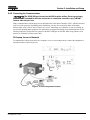
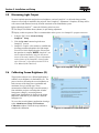
Download Link / Lien - FreeDCP.net

Transcript
CP2210
SETUP GUIDE
020-100524-02
CP2210
SETUP GUIDE
020-100524-02
NOTICES
COPYRIGHT AND TRADEMARKS
© 2010 Christie Digital Systems USA, Inc. All rights reserved.
All brand names and product names are trademarks, registered trademarks or trade names of their respective holders.
REGULATORY
The product has been tested and found to comply with the limits for a Class A digital device, pursuant to Part 15 of the FCC Rules. These limits
are designed to provide reasonable protection against harmful interference when the product is operated in a commercial environment. The
product generates, uses, and can radiate radio frequency energy and, if not installed and used in accordance with the instruction manual, may
cause harmful interference to radio communications. Operation of the product in a residential area is likely to cause harmful interference in which
case the user will be required to correct the interference at the user’s own expense.
This Class A digital apparatus complies with Canadian ICES-003.
Cet appareil numérique de la classe A est conforme à la norme NMB-003 du Canada.
이 기기는 업무용 (A 급 ) 으로 전자파적합등록을 한 기기이오니 판매자 또는 사용자는 이점을 주의하시기 바라며 , 가정 외의 지역에서 사용하는 것을
목적으로 합니다 .
GENERAL
Every effort has been made to ensure accuracy, however in some cases changes in the products or availability could occur which may not be
reflected in this document. Christie reserves the right to make changes to specifications at any time without notice. Performance specifications
are typical, but may vary depending on conditions beyond Christie's control such as maintenance of the product in proper working conditions.
Performance specifications are based on information available at the time of printing. Christie makes no warranty of any kind with regard to this
material, including, but not limited to, implied warranties of fitness for a particular purpose. Christie will not be liable for errors contained herein
or for incidental or consequential damages in connection with the performance or use of this material.
The product is designed and manufactured with high-quality materials and components that can be recycled and reused. This symbol
means that electrical and electronic equipment, at their end-of-life, should be disposed of separately from regular waste. Please dispose of the
product appropriately and according to local regulations. In the European Union, there are separate collection systems for used electrical and
electronic products. Please help us to conserve the environment we live in!
Canadian manufacturing facility is ISO 9001 and 14001 certified.
WARRANTY
For complete information about Christie’s limited warranty, please contact your Christie dealer. In addition to the other limitations that may be
specified in Christie’s limited warranty, the warranty does not cover:
a. Damage occurring during shipment, in either direction.
b. Projector lamps (See Christie’s separate lamp program policy).
c. Damage caused by use of a projector lamp beyond the recommended lamp life, or use of a lamp supplied by a supplier other than Christie.
d. Problems caused by combination of the product with non-Christie equipment, such as distribution systems, cameras, video tape recorders,
etc., or use of the product with any non-Christie interface device.
e. Damage caused by misuse, improper power source, accident, fire, flood, lightening, earthquake or other natural disaster.
f. Damage caused by improper installation/alignment, or by product modification, if by other than a Christie authorized repair service
provider.
g. For LCD projectors, the warranty period specified applies only where the LCD projector is in “normal use.” “Normal use” means the LCD
projector is not used more than 8 hours a day, 5 days a week. For any LCD projector where “normal use” is exceeded, warranty coverage
under this warranty terminates after 6000 hours of operation.
h. Failure due to normal wear and tear.
PREVENTATIVE MAINTENANCE
Preventative maintenance is an important part of the continued and proper operation of your product. Please see the Maintenance section for
specific maintenance items as they relate to your product. Failure to perform maintenance as required, and in accordance with the maintenance
schedule specified by Christie, will void the warranty.
Table of Contents
1: Introduction
1.1 Using this Manual........................................................................................................................1-1
1.1.1 Typographical Notations......................................................................................................1-1
1.2 Safety Warnings and Guidelines .................................................................................................1-2
1.2.1 Labels and Marking .............................................................................................................1-2
1.2.2 General Precautions .............................................................................................................1-2
1.2.3 AC/Power Precautions .........................................................................................................1-3
Power Cords and Attachments .............................................................................................1-3
1.2.4 Lamp Precautions ................................................................................................................1-3
Wear Protective Clothing .....................................................................................................1-3
Cool the Lamp Completely ...................................................................................................1-4
1.3 Purchase Record and Service Contacts .......................................................................................1-4
1.4 Projector Overview......................................................................................................................1-5
1.4.1 Key Features ........................................................................................................................1-5
1.4.2 How the Projector Works ....................................................................................................1-6
1.4.3 Air Filter Cover and Air Filter.............................................................................................1-6
1.4.4 Douser..................................................................................................................................1-7
1.4.5 Adjustable Feet ....................................................................................................................1-7
1.4.6 Lamp Door and Lamps ........................................................................................................1-7
1.4.7 LED Status Indicators ..........................................................................................................1-7
1.4.8 Optional - Motorized Auxiliary Lens Mount (MALM).......................................................1-7
1.4.9 Projection Lens ....................................................................................................................1-7
1.4.10 Security Locks ..................................................................................................................1-7
1.4.11 Source and Communication Panel ....................................................................................1-8
PIB Faceplate Connections ...................................................................................................1-8
PIB Faceplate Status Indicators ............................................................................................1-8
ICP Faceplate Connections ...................................................................................................1-9
1.4.12 Touch Panel Controller (TPC)..........................................................................................1-10
1.4.13 List of Components...........................................................................................................1-10
2: Installation and Setup
2.1 Permanent Power Connection .....................................................................................................2-1
2.2 Tools Required for Installation....................................................................................................2-1
2.3 Installation Instructions ...............................................................................................................2-2
2.3.1 Step 1: Position the Projector...............................................................................................2-2
2.3.2 Step 2: Adjust Tilt/Leveling ................................................................................................2-3
2.3.3 Step 3: Mount Touch Panel Controller (TPC) .....................................................................2-3
2.3.4 Step 4: Connect Exhaust Ducting (Optional) ......................................................................2-4
2.3.5 Step 6: Install Lens ..............................................................................................................2-5
Primary Zoom Lens Installation ...........................................................................................2-5
Anamorphic Lens Installation ..............................................................................................2-6
Wide Converter Lens (WCL) Installation ............................................................................2-6
Motorized Auxiliary Lens Mount (MALM) Installation (Optional) ....................................2-6
2.3.6 Step 7: Install First Lamp.....................................................................................................2-7
2.3.7 Step 8: Connect to Power.....................................................................................................2-8
CP2210 Setup Guide
020-100524-02 Rev. 1 (11-2010)
i
Table of Contents
2.3.8 Step 9: Connect Sources ......................................................................................................2-9
2.4 Connecting Sources .....................................................................................................................2-10
2.4.1 Cinema Servers ....................................................................................................................2-10
2.4.2 Connecting for Communications .........................................................................................2-11
PC/Laptop, Server or Network .............................................................................................2-11
2.5 Maximizing Light Output ............................................................................................................2-12
2.6 Calibrating Screen Brightness (fL) ..............................................................................................2-12
2.7 Basic Image Alignment ...............................................................................................................2-13
2.7.1 Basic Optical Alignment Procedure.....................................................................................2-13
2.8 Offset and Boresight Alignment ........................................................................................................... 2-13
2.8.1 Adjust Offset ........................................................................................................................2-13
2.8.2 Adjusting Left/Right Boresight............................................................................................2-14
Lens Mount Vertical Boresight .............................................................................................2-14
Lens Mount Horizontal Boresight ........................................................................................2-15
2.8.3 Add Anamorphic Lens .........................................................................................................2-16
2.8.4 Wide Converter Lens ...........................................................................................................2-16
2.9 Fold Mirror and Convergence Adjustments ................................................................................2-17
2.9.1 DMD Convergence ..............................................................................................................2-17
2.9.2 Fold Mirror Adjustment .......................................................................................................2-17
2.10 Calibrating the System...............................................................................................................2-18
2.10.1 Color Calibration...............................................................................................................2-18
2.10.2 Electronic Screen Masking ...............................................................................................2-18
3: Basic Operation
3.1 Powering Up/Powering Down the Projector................................................................................3-1
3.1.1 Powering Up the Projector ...................................................................................................3-1
3.1.2 Powering Down the Projector ..............................................................................................3-2
3.2 Using the Touch Panel Controller (TPC) ....................................................................................3-2
4: Maintenance
4.1 Maintaining Proper Cooling ........................................................................................................4-1
4.1.1 Ventilation............................................................................................................................4-1
4.2 Preventative Maintenance............................................................................................................4-1
4.2.1 Light Engine Air Filter (P/N: 003-002311-xx) ....................................................................4-1
4.2.2 Radiator Filter ......................................................................................................................4-1
4.2.3 Liquid Cooling System ........................................................................................................4-2
Filling the Coolant Reservoir ................................................................................................4-2
4.2.4 Optional: Exhaust Duct (P/N: 119-103105-xx) ...................................................................4-2
4.3 Maintenance and Cleaning...........................................................................................................4-3
4.3.1 Lamp ....................................................................................................................................4-3
4.3.2 Optical ..................................................................................................................................4-3
Optical Component Cleaning Supplies .................................................................................4-3
4.3.3 Cleaning the Lens.................................................................................................................4-4
4.3.4 Cleaning the Lamp Reflector ...............................................................................................4-4
4.3.5 Other Components ...............................................................................................................4-5
ii
CP2210 Setup Guide
020-100524-02 Rev. 1 (11-2010)
Table of Contents
Lamp Blower ........................................................................................................................4-5
4.3.6 Lamp Replacement ..............................................................................................................4-5
4.3.7 Rotating the Lamp ...............................................................................................................4-7
4.3.8 Air Filter Replacement.........................................................................................................4-8
Light Engine Air Filter .........................................................................................................4-8
Radiator Filter Cleaning .......................................................................................................4-8
4.4 Lens Replacement........................................................................................................................4-9
4.4.1 Remove Lens .......................................................................................................................4-9
4.4.2 Install New Lens ..................................................................................................................4-10
5: Troubleshooting
5.1 Power ...........................................................................................................................................5-1
5.1.1 Projector Does Not Power ON.............................................................................................5-1
5.2 Lamp ............................................................................................................................................5-2
5.2.1 Lamp Does Not Ignite..........................................................................................................5-2
5.2.2 Lamp Suddenly Goes OFF ..................................................................................................5-2
5.2.3 Flicker, Shadows Or Dimness .............................................................................................5-3
5.2.4 LampLOC™ Does Not Seem to Work................................................................................5-3
5.2.5 LiteLOC™ Does Not Seem to Work...................................................................................5-3
5.3 ILS ...............................................................................................................................................5-3
5.3.1 Reset the ILS........................................................................................................................5-3
5.3.2 Calibrate the ILS..................................................................................................................5-4
5.4 TPC..............................................................................................................................................5-4
5.5 Ethernet........................................................................................................................................5-4
5.5.1 Trouble Establishing Communication with Projector .........................................................5-4
5.6 Displays .......................................................................................................................................5-4
5.6.1 Blank Screen, No Display of Cinema Image .......................................................................5-4
5.6.2 Severe Motion Artifacts.......................................................................................................5-5
5.6.3 Image Appears Vertically Stretched or ‘Squeezed’ into Center of Screen..........................5-5
5.6.4 No Image, Just a Black Screen ............................................................................................5-5
5.6.5 No Image, Just Pink Snow...................................................................................................5-5
5.6.6 Colors in the Display are Inaccurate....................................................................................5-5
5.6.7 Display is Not Rectangular ..................................................................................................5-5
5.6.8 Display is “Noisy” ...............................................................................................................5-6
5.6.9 Display has Suddenly Frozen ..............................................................................................5-6
5.6.10 Data is Cropped from Edges .............................................................................................5-6
5.6.11 The Projector is ON, but There is No Display..................................................................5-6
5.6.12 The Display is Jittery or Unstable.....................................................................................5-6
5.6.13 The Display is Faint..........................................................................................................5-7
5.6.14 The Upper Portion of the Display is Waving, Tearing or Jittering...................................5-7
5.6.15 Portions of the Display are Cut OFF or Warped to the Opposite Edge............................5-7
5.6.16 Display Appears Compressed (Vertically Stretched) .......................................................5-7
5.6.17 Display Quality Appears to Drift from Good to Bad, Bad to Good .................................5-7
CP2210 Setup Guide
020-100524-02 Rev. 1 (11-2010)
iii
1 Introduction
1.1
Using this Manual
USERS/OPERATORS: This manual is intended for trained users authorized to operate professional highbrightness projection systems, located in restricted areas, such as projection rooms in theatres. Such users may
also be trained to replace the lamp and air filter, but cannot install the projector or perform any other functions
inside the projector. NOTE: Only personnel trained specifically by Christie on lamp replacement and lamp
safety may handle the lamp.
SERVICE: Only qualified Christie trained service technicians knowledgeable about all potential hazards
associated with high voltage, ultraviolet exposure and high temperatures generated by the lamp and associated
circuits are authorized to 1) assemble/install the projector and 2) perform service functions inside the projector.
This manual contains the following sections:
•
•
•
•
•
Section 1 Introduction
Section 2 Installation and Setup
Section 3 Basic Operation
Section 4 Maintenance
Section 5 Troubleshooting
Disclaimer: Every effort has been made to ensure the information in this document is accurate and reliable. However, due
to constant research, the information in this document is subject to change without notice. Christie Digital Systems
assumes no responsibility for omissions or inaccuracies. Updates to this document are published regularly, as required.
Please contact Christie Digital Systems for availability.
1.1.1 Typographical Notations
The following notations are used throughout this manual:
• References to specific areas of the document appear italicized and underlined. When viewed online the text
appears in blue indicating a direct link to that section. For example, Section 2 Installation and Setup.
• References to other documents appear italicized and bold, such as Service Manual.
• References to software menus and available options appear bold, such as Main panel, Preferences.
• User input or messages that appear on screen, in status display units or other control modules appear in
Courier font. For example. “No Signal Present”, Login: christiedigital.
• Error codes, LED status appear in bold, e.g. LP, A1 etc.
• Operational states of modules appear capitalized, such as power ON/OFF.
CP2210 Setup Guide
020-100524-02 Rev. 1 (11-2010)
1-1
Section 1: Introduction
1.2
Safety Warnings and Guidelines
1.2.1 Labels and Marking
Observe and follow any warnings and instructions marked on the projector.
DANGER Danger symbols indicate a hazardous situation which, if not avoided, will result
in death or serious injury. This signal word is to be limited to the most extreme situations.
WARNING Warning symbols indicate a hazardous situation which, if not avoided, could
result in death or serious injury.
Caution symbols indicate a hazardous situation which, if not avoided, could
result in minor or moderate injury.
NOTICE! Addresses practices not related to personal injury.
NOTICE! Observe and follow any warnings and instructions marked on the projector.
The exclamation point within the equilateral triangle indicates related operating/maintenance instructions
in the documentation accompanying the projector.
The lightning flash and arrowhead symbol within the equilateral triangle indicates non-insulated
“dangerous voltage” within the projector's enclosure that may be of sufficient magnitude to constitute a risk of
electric shock.
1.2.2 General Precautions
WARNING Never look directly into the projector lens or at the lamp. The extremely high
brightness can cause permanent eye damage. For protection from ultraviolet radiation, keep all
projector housings intact during operation. Protective safety gear and safety goggles are recommended
when servicing.
WARNING FIRE HAZARD! Keep hands, clothes, and all combustible material away from the
concentrated light beam of the lamp.
Position all cables where they cannot contact hot surfaces or be pulled or
tripped over.
1) The American Conference of Governmental Industrial Hygienists (ACGIH)
recommends occupational UV exposure for an 8-hour day to be less than 0.1 microwatts per square
centimeters of effective UV radiation. An evaluation of your workplace is advised to assure employees
are not exposed to cumulative radiation levels exceeding the government guidelines for your area. 2)
Be aware that some medications are known to increase sensitivity to UV radiation.
This projector must be operated in an environment that meets the operating range specification, as listed in
Section 6 - Specifications from the CP2210 User Manual (020-100410-xx).
1-2
CP2210 Setup Guide
020-100524-02 Rev. 1 (11-2010)
Section 1: Introduction
1.2.3 AC/Power Precautions
WARNING
1) Use only the AC power cord supplied. DO NOT attempt operation if the AC supply is not
within the specified voltage and power range. For details, refer to Section 6 - Specifications
from the CP2210 User Manual (020-100410-xx).
2) As a safety feature the projector is equipped with a three-wire plug with a third
(grounding) pin. If you are unable to insert the plug into the outlet, contact an electrician to
have the outlet replaced. DO NOT defeat the safety purpose of the grounding-type plug.
3) DO NOT attempt operation if the AC supply is not within the rated voltage range, as
specified on the licence label.
4) Disconnect projector from AC before opening any enclosure.
1) DO NOT allow anything to rest on the power cord. Locate the projector where the cord
cannot be abused by persons walking on it or objects rolling over it. Never operate the
projector if the power cable appears damaged in any way.
2) DO NOT overload power outlets and extension cords as this can result in fire or shock
hazards.
3) Note that only qualified service technicians are permitted to open any enclosure on the
product and only if the AC has been fully disconnected from the product.
Power Cords and Attachments
WARNING 1) The North American rated line cord is provided with each projector. Ensure
that you are using a line cord, socket and power plug that meets the appropriate local rating
standards. 2) Use only an AC power cord recommended by Christie. Do not attempt
operation if the AC supply and cord are not within the specified voltage and power range.
Use only the attachments and/or accessories recommended by Christie. Use of others may result in the risk of
fire, shock or personal injury.
1.2.4 Lamp Precautions
DANGER EXPLOSION HAZARD! Wear authorized protective safety gear whenever the
lamp door is open! Never attempt to remove the lamp directly after use. The lamp is under
significant pressure when hot and cold, and may explode, causing personal injury and/or
property damage.
Any lamp used in the CP2210 is under high pressure and must be handled with great care at all times. Lamps
may explode if dropped or mishandled.
Wear Protective Clothing
Never open the lamp door unless you are wearing authorized protective clothing such as that included in a
Christie Protective Clothing Safety Kit (P/N: 598900-095). Recommended protective clothing includes, but
may not be limited to a polycarbonate face shield, protective gloves, and a quilted ballistic nylon jacket or a
welder’s jacket. NOTE: Christie’s protective clothing recommendations are subject to change. Any local or
federal specifications take precedence over Christie recommendations.
CP2210 Setup Guide
020-100524-02 Rev. 1 (11-2010)
1-3
Section 1: Introduction
Cool the Lamp Completely
DANGER Lamp may explode causing bodily harm or death. 1) Always wear protective
clothing whenever lamp door is open or while handling lamp. 2) Ensure those within the
vicinity of the projector are also suited with protective clothing. 3) Never attempt to access
the lamp while the lamp is ON. Wait at least 10 minutes after the lamp turns OFF before
powering down, disconnecting from AC and opening the lamp door.
The arc lamp operates at a high pressure that increases with temperature. Failure to allow the lamp to
sufficiently cool prior to handling increases the potential for an explosion causing personal injury and/or
property damage. After turning the lamp OFF, it is crucial that you wait at least 15 minutes before disconnecting AC and opening the lamp door. This provides enough time for the cooling fans to properly cool the lamp.
Ensure the lamp is completely cooled before handling and always wear protective clothing!
For all other precautions critical for safe removal and replacement of the lamp, refer to 4.3.6 Lamp
Replacement, on page 4-5.
1.3
Purchase Record and Service Contacts
Whether the projector is under warranty or the warranty has expired, Christie’s highly trained and extensive
factory and dealer service network is always available to quickly diagnose and correct projector malfunctions.
Complete service manuals and updates are available for all projectors. Should a problem be encountered with
any part of the projector, contact your dealer. In most cases, servicing is performed on site. If you have
purchased the projector, fill out the information below and keep with your records.
Table 1.1 Purchase Record
Dealer:
Dealer or Christie Sales/Service
Contact Phone Number:
Projector Serial Number*:
Purchase Date:
Installation Date:
* The serial number can be found on the license label located on the front panel.
Table 1.2 Ethernet Settings
Default Gateway:
Projector IP Address:
Subnet Mask:
1-4
CP2210 Setup Guide
020-100524-02 Rev. 1 (11-2010)
Section 1: Introduction
1.4
Projector Overview
The CP2210 is a professional quality, easy-to-use
DMD™ projector utilizing Digital Light Processing
(DLP™) Cinema technology from Texas Instruments.
It’s all-in-one design integrates all components in a
sleek projection head that can be table-top mounted
or used with the optional rack stand. Integrating
smoothly into traditional projection environments
such as theatres and other wide screen exhibitor
venues, the CP2210 offers stunning wide screen,
high-resolution cinema images that remain flawless
from first release to final show. The CP2210
interfaces with local networks typical in theatres
throughout the world, and can be expanded even
further by connecting non-cinema DVI source
material for multimedia presentations from a variety
of formats.
1.4.1 Key Features
•
•
•
•
•
•
•
•
•
•
•
•
•
•
•
•
•
Figure 1-1 CP2210 Projector
Three-chip mDC2K DLP Cinema® light engine.
.98” “mDC2K” panel format: 2,048(H) x 1,080 (V).
Maximum light output of 12, 500 centre lumens, depending on lamp used.
Available for use with 2.0kW, 1.8kW and 1.4kW Xenon lamps supporting theatre screens up to 30 feet in
width.
All-in-one design (including Lamp Power Supply).
CineBlack™ contrast management for contrast ratios of 450:1 ANSI and 2000:1 full field.
CinePalette™ color management for film-like colorimetry.
Easily accessible Input/Output panel located on the operator side of the projector with access to:
• Two SMPTE 292M inputs, intended for cinema content – operable as two independently selectable inputs
or as a single dual-link input (both inputs used simultaneously for one source).
• Two DVI-D inputs, intended for alternative content – operable as two independently selectable inputs or as
a single twin- or dual-link input (dual-link requires optional adapter).
• RS232 Connections – one for Projector Intelligence Board (PIB) and one for TI electronics (ICP).
• Single projector Ethernet network connection.
• Dedicated 3D connection plug for interfacing with third party 3D systems.
Easy-to-read three coloured LED indicators on the rear corners of the projector for status indication.
Supports CineLink® II link encryption on SMPTE 292M inputs.
LiteLOC™ feature for constant image brightness.
LampLOC™ feature for motorized three-axis lamp alignment (automatic or individually adjusted).
Available suite of field-interchangeable “prime” zoom lenses supporting 1.85:1 and 2.39:1 image formats.
Prime lens provides electronic adjustment of focus (stepper motor). *Manual adjustment is available in case of motor failure.
Prime lens provides electronic adjustment of zoom (stepper motor).
Lens mount provides electronic adjustment of horizontal and vertical offset (stepper motors).
Optional Motorized Auxiliary Lens Mount for flat to scope format conversion (for optional 1.25x anamorphic or 1.26x converter lens).
CP2210 Setup Guide
020-100524-02 Rev. 1 (11-2010)
1-5
Section 1: Introduction
•
•
•
•
•
•
•
•
•
•
•
•
•
•
•
•
•
Lamp easily replaceable via locked door on rear of projector.
Electronically operated “quick” douser.
Field adjustable RGB Convergence.
Easy-to-remove Light Engine including a permanently mounted handle and quick disconnects for cooling
and electrical connections.
Secure, encrypted communication protocol, with multi-level password access.
Content protected by a high-security Medeco® lock on front electronics compartment and SPB2 boundary
per DCI Digital Cinema System Specification v1.2.
Complies with DCI Digital Cinema System Specification v1.2 mandated security requirements.
Air filter for projection compartment that is easily replaceable with common tools.
Optional Rack Mount Stand that supports the product for projection out standard theatre port windows and
provides for rack mounting of hardware.
Capability to split power supply to allow use of UPS (Uninterruptable Power Supply) to power head electronics.
Touch Panel Controller (TPC) running Windows XPe for main projector interface. TPC can be removed
from the projector for ease of use or alternate mounting with optional extension cable. Ensure you have the
latest software by visiting www.christiedigital.com.
Seamless switching between 292 and DVI inputs.
Capable of supporting an internal image media block.
Easily serviceable LVPS with quick disconnects.
Separate and easily serviceable standby LVPS with quick disconnects.
Easy access for Lamp Power Supply removal.
Projector can be self-cooling or utilize external air extraction, depending on theatre configuration.
1.4.2 How the Projector Works
The CP2210 accepts a variety of cinema or DVI-compatible “non-cinema” signals for projection on screens
typical in commercial theatre or other large screen applications. High-brightness light is generated by a
short arc Xenon lamp, then modulated by three Digital Micromirror Device (DMD) panels responding to
incoming data streams of digitized red, green and blue color information. As these digital streams flow from
the source, light from the responding “on” pixels of each panel is reflected, converged and then projected to the
screen through one or more front lenses, where all pixel reflections are superimposed in sharp full-color
images.
1.4.3 Air Filter Cover and Air Filter
Located directly behind the air filter cover is a field replaceable air filter. The air filter is responsible for
filtering the intake air before it begins circulating in the front compartment to cool the main electronics.
Replace the air filter whenever the lamp is replaced or sooner in dusty/dirty environments. Check the condition
monthly. Refer to 4.3.8 Air Filter Replacement, on page 4-8 for complete instructions.
1-6
CP2210 Setup Guide
020-100524-02 Rev. 1 (11-2010)
Section 1: Introduction
1.4.4 Douser
For most instances, use the douser control buttons on the TPC to blank the display for instant picture muting.
Closing the douser rotates a shutter blade in front of the illumination system and reduces lamp power to
conserve lamp life.
1.4.5 Adjustable Feet
For many cinema installations, the projector is inclined slightly forward to match screen tilt and to minimize
the amount of vertical offset required. Turn the adjustable feet to increase or decrease the projector height as
needed for proper leveling and/or slight tilt. Refer to 2.3.2 Step 2: Adjust Tilt/Leveling, on page 2-3 for details
on how to adjust the feet and how to properly secure the projector.
1.4.6 Lamp Door and Lamps
Located on the back of the projector is the lamp access door designed with a mid-security lock. The lamp door
must remain closed and locked for all normal operation. Lamp replacement should only be performed by
qualified technicians.
The projector is designed to operate with 2.0kW, 1.8kW and 1.4kW lamps. For a complete list of available
lamp types refer to Section 6 - Specifications from the CP2210 User Manual (020-100410-xx).
1.4.7 LED Status Indicators
Located in the rear corners of the projector are two sets of LEDs, which illuminate to provide continuous
feedback of the projector’s status. Refer to Section 3 - Operation from the CP2210 User Manual (020100410-xx) for details on the various LED states.
1.4.8 Optional - Motorized Auxiliary Lens Mount (MALM)
The MALM assembly is an optional hardware component, which when needed can be used to switch from flat
to “scope” formats. This assembly can be secured to the projector base and supports either a 1.25x anamorphic
lens or a 1.26x wide converter lens (WCL). The drive and control electronics package for this motorized
accessory lens mount communicates with and is controlled by the projector over a 9-pin subminiature D cable
that connects to the Auxiliary Input Panel.
1.4.9 Projection Lens
A variety of lenses can be used with the CP2210. Refer to the Section 6 - Specifications from the CP2210
User Manual (020-100410-xx) for a list of available lenses
1.4.10 Security Locks
Critical internal components and/or connections are protected by various security locks on projector covers/
access panels. This safeguard enables only authorized personnel to access certain restricted areas of the
projector. The projector’s panels cannot be removed with standard tools unless the key locks are open.
• Panels with high-security lock: Light Engine and Cardcage
• Panels with low-security lock: Rear Access Door
• No locks: Air Filter Access Panel
CP2210 Setup Guide
020-100524-02 Rev. 1 (11-2010)
1-7
Section 1: Introduction
1.4.11 Source and Communication Panel
PIB Faceplate Connections
Located on the operator’s side of the projector (left side) is a communication panel that provides connection of
external devices such as servers and a controller.
• Ethernet: Use the 10Base-T/100Base-TX Ethernet port for network connection to the projector.
• GPIO: Connect external I/O devices, such as the Christie ACT, for remote control of a limited number of
projector functions. Refer to Appendix C - GPIO Port from the CP2210 User Manual (020-100410-xx) for
GPIO pinouts.
• SCCI: A Simple Contact Closure Interface (SCCI) port that provides the following functions upon a simple
dry contact closure: Lamp ON/OFF and Douser Open/Closed. Refer to Appendix B: SCCI Port from the
CP2210 User Manual (020-100410-xx) for SCCI pinouts.
• RS232 ICP: Connect a PC or laptop for direct DLP communication. Trained users required.
• RS232 PIB: Utilizes Christie-proprietary protocol and is intended for Christie accessories or third-party
automation equipment.
• 3D: Connect a variety of 3D products to this connector, such as MasterImage or Real D for polarizing 3D
content during projection.
• Marriage: Marriage must be established to allow the projector to play encrypted content. This means the
security boundaries SPB1 and SPB2 are physically and electrically connected and that marriage is monitored
24/7. Marriage is initiated from a Wizard application on the TPC. A user with the appropriate credentials is
prompted to press the marriage button to establish marriage. If the button is pressed any other time it is
ignored. Marriage cannot be established remotely.
• Emergency Start: This button is recessed into the faceplate to prevent accidental activation. It should only
be used when the TPC has failed or is disconnected. When pressed, the projector is powered on, the lamp is
turned on and the douser is opened. When you press and hold this button, the douser is closed and the lamp is
turned off, but power is still on.
• Reset: This button is slightly recessed into the faceplate to prevent accidental activation. It’s main purpose is
to reset the electronics of the projector. After re-booting, the projector will return to its previous power mode
(STANDBY or FULL Power), however the lamp will not strike automatically and requires manual striking.
• DVI-A / DVI-B: Connect a variety of non-cinema video and graphics sources to either of these identical
single-link DVI ports. These are single-link ports for single-link cables/connectors only. The connectors can
be used together as a twin-link DVI port.
• HD-SDI A/HD-SDI-B: Connect a variety of high-definition cinema sources to these SMPTE 292M bitserial standard interface BNCs. The connectors can be used together to deliver Dual Link HD-SDI following
the SMPTE 372M standard.
PIB Faceplate Status Indicators
• STBY: Standby power (Single Color Green) indicates the presence of +24V from the standby power supply.
• OFF: Indicates no standby power (breaker OFF or Standby power failure).
• Green: Indicates standby power.
• PWR: Main power (Single Color Green) indicates the presence of +24V from the Low Voltage Power
Supply (LVPS).
• OFF: No LVPS power (STANDBY mode or breaker OFF).
• Green: Indicates full power.
1-8
CP2210 Setup Guide
020-100524-02 Rev. 1 (11-2010)
Section 1: Introduction
• RUN: Blinking heartbeat (bi-color green/yellow).
• OFF or Solid Green: Indicates projector not functioning properly.
• Blinking Green: OK (software/communication/OS/ICP/Enigma/IMB if present are operating
normally).
• Solid Yellow: Communication error. NiOS functioning OK, but can no longer communicate with TPC.
• PIB: Projector Intelligence Board Status (Bi-color Red/Green)
• OFF: Not detected.
• Red: Detected communication problems etc.
• Blinking Red: PIB card seating error.
• Green: Detected and working properly.
• ICP: Integrated Cinema Processor Status (Bi-color Red/Green)
• OFF: Not detected.
• Red: Detected communication problems etc.
• Green: Detected and working properly.
• LD: Link Decryptor (Enigma) Status (Bi-color Red/Green)
• OFF: Not detected.
• Red: Detected communication problems etc.
• Green: Detected and working properly.
• IMB: Image Media Block Status (Bi-color Red/Green)
• OFF: Not detected.
• Red: Detected communication problems etc.
• Green: Detected and working properly.
ICP Faceplate Connections
The ICP board provides the image processing electronics for the projector. The ICP faceplate includes a
number of LEDs that are only functional when the projector is in full power mode.
• REGEN: (Regulators Enabled) This LED indicates the presence of the internal regulator enable signal.
When illuminated BLUE the internal regulators are enabled. When OFF, not enabled.
• SOFTST: (Software State) This LED indicates the state of the software application. When OFF, in a Fail
state (0). When RED, in a Fail state (1). When YELLOW, in a Fail state (2). When GREEN, status OK.
• OSST: (Operating System State) This LED indicates the state of the operating system. When OFF, in a Fail
state (0). When RED, in a Fail state (1), When YELLOW, in a Fail state (2). When GREEN, status OK.
• FMTST: (FMT FPGA State) This LED indicates the configured state of the FMT FPGA. When RED,
unable to configure FPGA with Main or Boot application. When YELLOW, in Boot application. When
GREEN, in Main application.
• ICPST: (ICP FPGA State) This LED indicates the configured state of the ICP FPGA. When RED, unable to
configure FPGA with Main or Boot application. When YELLOW, in Boot application. When GREEN, in
Main application.
• Port A / Port B: Indicates the status of the ICP input port A or B. When OFF, no source is present. When
GREEN, active source present.
• USB 1 / USB 2: For future use.
CP2210 Setup Guide
020-100524-02 Rev. 1 (11-2010)
1-9
Section 1: Introduction
1.4.12 Touch Panel Controller (TPC)
The TPC is a portable, touch-sensitive screen used to control the projector. It is mounted to the rear of the
projector and can be adjusted at any angle using the flexible double ball joint mount for convenient viewing
and flexible operation in various installation configurations. The TPC provides users with a means for
monitoring operation and status of the projector. Users can turn the lamp ON/OFF, select a specific source/
input, and obtain basic status information. Depending on the installation, the TPC can remain mounted to the
projector or wall mounted anywhere else at the site. An optional extension cable is also available, which can be
purchased separately to provide TPC access up to 100 feet away.
1.4.13 List of Components
Ensure the following components were received with the projector:
Projector with Touch Panel Controller
User Manual
Warranty Card
Web Registration Form
Line Cord
NOTE: Lamp and Lens supplied separately.
1-10
CP2210 Setup Guide
020-100524-02 Rev. 1 (11-2010)
2 Installation and Setup
WARNING
• All installation procedures must be performed by a qualified technician in a restricted access
location.
• Never operate the projector without all of its covers in place.
• Projector uses a high-pressure lamp that may explode if improperly handled. Always wear
manufacturer approved protective safety clothing (gloves, jacket, face shield) whenever the
lamp door is open or while handling the lamp. Lamp installation/replacement requires a
qualified technician.
• Two people are required to safely lift and install the projector.
• When transporting the projector from a cold environment it is essential the projector
acclimatizes to the operating environment before powering up for a minimum of three
hours after unpacking. Failure to ensure the projector has properly acclimatized could
damage projector electronics. This applies to the lamp as well. The lamp will be damaged if
it is powered ON when below room temperature. Lamps should be stored between 25-65°C
(77-149°F).
• Auto LampLOC™ must be run any time the projector is physically moved or when it has been
levelled.
This section explains how to install, connect and optimize the projector for delivery of superior image quality.
NOTE: Illustrations are graphical representations only and are provided to enhance the understanding of the
written material.
2.1
Permanent Power Connection
WARNING No protective device is provided in the neutral conductor.
• A single-phase 20A UL listed connection of AC power suply is required to accomodate the detachable projector plug.
• The power supply, along with protection from short-circuits must be must be part of the building installation.
• Protective devices are integrated into the equipment.
2.2
Tools Required for Installation
Before you begin installation, it is important to fully understand all site requirements and characteristics, and
that you have the following tools and components on hand.
19mm wrench
Protective clothing/safety gear (required when handling the lamp)
Lamp
CP2210 Setup Guide
020-100524-02 Rev. 1 (11-2010)
2-1
Section 2: Installation and Setup
2.3
Installation Instructions
2.3.1 Step 1: Position the Projector
WARNING Two people are required to safely lift and install the projector.
Auto LampLOC™ must be run any time the projector is physically moved or
when it has been levelled.
1. An optional rack stand (P/N: 108-282101-xx) is available for use with the projector. For installation
instructions, refer to the Rack Stand Installation Instruction Sheet (P/N: 020-100060-xx). NOTES: 1)
When using the rack stand, the foot lock brackets are a mandatory safety measure to prevent the projector
from tipping. 2) The rack stand’s feet are used for leveling only and not for tilting the projector. To prevent
tipping ensure the required accessories supplied by Christie are used.
2. Position the projector at an appropriate throw distance (projector-to-screen distance) and vertical position.
Ideally, center the projector with the theatre screen. If competing for space with an already present film
projector, aim the projector slightly off-center, as shown in . This will slightly increase side keystoning, but
will minimize the horizontal lens offset required. NOTE: Unlike film projectors, it is best to keep the
projector lens surface as parallel to the screen as possible, even if significantly above the screen center.
When a particularly short throw distance combines with a very wide screen, you may have to forfeit some
aim and stay more parallel to the screen. In such cases, some lens offset can reduce the keystone distortion.
3. Once you have completed the remaining installation steps and the projector is up-and-running, adjust
precise image geometry and placement, as described in 2.7.1 Basic Optical Alignment Procedure, on page
2-13.
Figure 2-1
2-2
CP2210 Setup Guide
020-100524-02 Rev. 1 (11-2010)
Section 2: Installation and Setup
2.3.2 Step 2: Adjust Tilt/Leveling
Disconnect from AC for these alignments. Images are not yet needed.
NOTICE! The front-to-back tilt of the projector must not exceed 15°. This limit ensures safe
lamp operation and proper position of the liquid cooling reservoir in the projector.
For an ideal installation, the CP2210 lens surface should be centered and
parallel to the theatre screen. This orientation helps to ensure optimized lens
performance with minimal offset. Choose a sturdy mounting surface that
allows for this. If this position is not possible (such as when the projector is
significantly higher than the center of the screen), it is better to rely on
offset rather than extra tilt. Check with theatre personnel for the degree of
screen tilt or measure this incline with a protractor at the screen. Tilt the
projector to match the screen tilt angle by extending or retracting the
projector’s four adjustable feet. For best optical performance, avoid tilting
the projector excessively. Use vertical offset of the lens instead.
To adjust the height or level of the projector, extend or retract the adjustable
feet located on the bottom of the projector by rotating them. Once the
required adjustment is made, tighten the lock nut. (Figure 2-2)
Figure 2-2 Adjusting
2.3.3 Step 3: Mount Touch Panel Controller (TPC)
The TPC comes pre-assembled with its base and mounting arm.
1. Loosen the mounting arm just enough for the end to fit over the ball joint located on the rear panel of the
projector. (1.)
Figure 2-3 Loosen Mounting Arm
2. Tighten the mounting arm until it fits snug on the ball joint. (Figure 2-4)
Figure 2-4 Tighten Mounting Arm
3. Connect the cable from the TPC to the connector located on the projector’s rear panel.
4. Adjust the angle of the TPC as desired.
CP2210 Setup Guide
020-100524-02 Rev. 1 (11-2010)
2-3
Section 2: Installation and Setup
2.3.4 Step 4: Connect Exhaust Ducting (Optional)
If the room the projector is installed in is not
equipped to ventilate up to 11,000 BTU (per
hour) the optional duct (P/N: 119-103105xx) must be installed to emit the constant
stream of warm exhaust air from the
projector to the outside of the building.
Connect pre-installed outside-venting
ductwork via the 8” inside diameter fireproof
ducting material attached to the projector’s
top exit port. Confirm that 1) there are no
obstructions or ‘kinks” within the ducting, 2)
all air intake areas of the projector are clear
and exposed, 3) The preinstalled outsideventing duct should be rigid at the projector
and must also include a heat extractor/blower
that maintains at least 450 CFM (212 L/s)
when measured at the projector exhaust opening.
Figure 2-5 Connect Ducting
Calculating CFM in the 8” duct (Imperial): Use an anemometer to measure the ft/min or ft/sec at the rigid
end of the open duct that connects to the projector. Ensure the measurement is taken right at the very end and
without the projector connected. Then multiply the reading by the cross-sectional area of the 8” duct to
calculate the cubic feet/min airflow.
Imperial formula: Measured linear ft/min x 0.34 = CFM)
Calculating the flow rate in the 200mm duct (Metric): Use an anemometer to measure the air velocity in m/
sec at the rigid end of the open duct that connects to the projector. Ensure the measurement is taken right at the
very end and without the projector connected. Then multiply the reading by the cross-sectional area of the
200mm duct to calculate the airflow in L/s.
Metric formula: Measured linear air velocity m/s x 31.4 = L/s
Calculations should show 450 CFM (212 L/s) airflow in the 8”/200mm exhaust duct. DO NOT mount the
extractor on the projector as this may introduce some vibration into the image.
2-4
CP2210 Setup Guide
020-100524-02 Rev. 1 (11-2010)
Section 2: Installation and Setup
2.3.5 Step 6: Install Lens
The lens seals the projector, preventing contaminants from entering the area of
the main front electronics. It is important a projector never be operated without a lens
installed.
Primary Zoom Lens Installation
1. Turn the lens clamp to the OPEN position
(Figure 2-6).
2. Remove the two hex screws from the lens mount
(Figure 2-7).
3. Orient the lens so the lens retaining ring mounts line
up with the lens mount. Fully insert the assembly
straight into the lens mount opening without turning.
(Figure 2-6). Magnets, mounted inside the lens
mount, help to properly guide the lens. When you hear
a clicking sound it indicates the lens has made contact
with the magnets. These magnetic guides ensure the
lens is properly seated inside the mount, that the
aperture is orientated correctly and that the connector
for motorized zoom and focus is properly connected.
Figure 2-6 Insert Lens
4. Secure the two hex screws and position the lens clamp
DOWN to lock the lens assembly in place (Figure 2-7).
Figure 2-7 Lock Lens in Place
CP2210 Setup Guide
020-100524-02 Rev. 1 (11-2010)
2-5
Section 2: Installation and Setup
Anamorphic Lens Installation
1. Install the M-MALM according to the instructions provided with the kit. Ensure the primary lens is
optimized first for best optical alignment, offset and boresight.
2. Anamorphic orientation: Loosen the holding clamp on the auxiliary lens mount and adjust rotation of the
whole anamorphic lens so the image remains perfectly square with anamorphic in and out.
3. Image shift: Adjust location of anamorphic lens so the image does not shift left or right with the
anamorphic lens IN and OUT.
4. Vignetting: Adjust location of anamorphic lens so the image passes through the center as much as possible
without vignetting or reducing side or corner brightness, especially in wide angle projection.
5. Focus primary lens: With the anamorphic lens not in place, re-focus the primary lens. The goal is good
focus at center and on all sides. Now add the anamorphic lens and check focus again.
6. Focus anamorphic lens: If center-to-edge horizontal focus in the image needs improvement, focus the
anamorphic lens - rotate its focus barrel as needed.
Wide Converter Lens (WCL) Installation
1. Install the Auxiliary Lens Mount and WCL according to the instructions provided with the kit. Ensure the
primary lens is optimized first for best optical alignment, offset and boresight.
2. Image shift: Adjust the vertical and horizontal position of the WCL to align it with the already adjusted
prime lens.
3. Pitch Adjustment: Adjust pitch, either up or down to equalize the top and bottom clearance to the prime
lens barrel.
4. Yaw Adjustment: Adjust yaw so the clearance between both lens barrels is equal from side-to-side.
Motorized Auxiliary Lens Mount (MALM) Installation (Optional)
The M-MALM assembly is an optional hardware
component, which when needed can be used to
switch from flat to “scope” formats. This assembly
can be secured to the projector base and supports
either a 1.25x anamorphic lens or a 1.26x wide
converter lens (WCL). The drive and control
electronics package for this motorized accessory
lens mount communicates with and is controlled by
the projector over a 9-pin subminiature D cable that
connects to the User I/O panel. For details, refer to
the Motorized Auxiliary Lens Mount (M-MALM)
Installation Instruction Sheet (P/N: 020-100188xx).
2-6
Figure 2-8 MALM Overview
CP2210 Setup Guide
020-100524-02 Rev. 1 (11-2010)
Section 2: Installation and Setup
2.3.6 Step 7: Install First Lamp
DANGER
• Only personnel trained specifically by Christie on lamp replacement and lamp safety may
handle the lamp. High-pressure lamp may explode if improperly handled.
• Always wear Christie approved protective safety clothing (P/N: 59-8900-095) whenever the
internal lamp door is open or while handling the lamp.
• Never attempt to access the lamp while the lamp is ON. Wait at least 15 minutes after the
lamp turns OFF before powering down, disconnecting from AC and opening the internal
lamp door.
1) Auto LampLOC™ must be run any time the lamp is removed (inspected or
changed). 2) DO NOT place heavy objects on the open rear access door.
1. Open lamp door. Using the security key provided, open the rear door to access the projector components.
The door mechanism includes a safety interlock switch, which turns lamp power OFF and prevents it from
being turned ON when the door is open. The interlock wiring connects directly to the Lamp Power Supply
(LPS).
2. Open internal lamp door. Manually turn the two thumbscrews on the internal lamp door counterclockwise.
3. Install the lamp. Refer to 4.3.6 Lamp Replacement, on page 4-5 for lamp installation instructions.
Observe all warnings, and wear protective clothing and shielding.
Table 2.1 Lamp Types Available for CP2210
Lamp
Type
1.4kW
CXL-14M
1.8kW
CDXL-18SD
2.0kW
CDXL-20SD
CP2210 Setup Guide
020-100524-02 Rev. 1 (11-2010)
2-7
Section 2: Installation and Setup
2.3.7 Step 8: Connect to Power
WARNING =
• DO NOT attempt operation if the AC supply and cord are
not within the specified voltage and power range. Refer
to Section 6 - Specifications from the CP2210 User Manual (020-100410-xx).
• Always power down the projector before unplugging the
AC line cord. The appropriate ratings for the projector are
listed on the licence label (located on the back of the projector). Wait 15 minutes for the main exhaust fan to turn
OFF and for the lamp to cool sufficiently before unplugging the projector.
• Ground (earth) connection is necessary for safety. Never
compromise safety by returning the current through the
ground. Connect ground FIRST to reduce shock hazard
from high leakage.
Figure 2-9
AC Receptacle
NOTICE! Use the line cord provided with each projector. DO NOT compromise safety by
using other connectors. For all other regions, ensure a line cord, power plug and socket that
meet the appropriate rating standards are used. For more information, refer to 3.1.1
Powering Up the Projector, on page 3-1.
This is a manual power-up
procedure. Some installations may
include an automation system that
controls lamp ignition in conjunction
with other theater variables, such as
house lights, audio and the start of
the feature from a digital media
storage device/server.The projector
is powered by 200-240VAC power
from the theater. The switching
Lamp Power Supply (LPS) provides
a well regulated DC current up to 85
amps with a maximum LPS power of
2.1kW. The power output from the
LPS is controlled by the PIB, via a
Figure 2-10 Connecting to Power
dedicated ‘RS232’ connection from
the Backplane to the LPS. A switch
selectable secondary 100-240VAC inlet is provided, allowing the main electronics to be powered separately,
via a universal 100-240VAC UPS. The main LPS is powered through the main 200-240VAC inlet. A discrete
AC switch above the 2 inlets (Figure 2-9) allows the user to select whether the main electronics are powered
from the main inlet (requiring only 1 power cord to supply the entire unit), or the secondary inlet supplied by
the UPS, via an additional line cord (not provided).
1. Connect the projector’s line cord to the AC receptacle at the lower-left rear corner of the projector and to
proper AC - the outlets must be near the equipment and easily accessible. Use only the line cord provided
with the projector or a power cord of appropriate ratings that comply with regional standards. When the
main inlet is used the AC switch must be set to the left (Figure 2-10).
2-8
CP2210 Setup Guide
020-100524-02 Rev. 1 (11-2010)
Section 2: Installation and Setup
2. An optional feature to power all electronics through a UPS is available using the secondary inlet (cord not
provided). When the secondary inlet is used the AC switch must be set to the right (Figure 2-10). This
feature enables users to power all electronics through a UPS, which minimizes downtime in the event of a
brief power outage.
2.3.8 Step 9: Connect Sources
Once the lamp is installed, the projector is essentially ready for operation. Although an image is not required at
this time, it is recommended that external cinema servers and sources be connected. Before igniting the lamp
for the first time, it is essential the following steps be completed to ensure successful communication.
1. Assign the projector a unique IP address. Each projector is given a default IP address, however if you
are connecting the projector to an existing network you must give it a new IP address. For first time
installations, assign the IP address in Administrator Setup: Communications Configuration window
using the Touch Panel Controller.
2. Set the baud rate. Set the baud rate to match the external device connected (such as a server). The
projector’s default baud rate is 115200 bps.
3. Enter Lamp information. From the Advanced Setup: Lamp History window define the type of lamp
installed, serial number and the number of hours currently logged on the lamp (if any).
4. Power-up the projector.
a. On the TPC, click and hold the Power ON button for 1/4 second to fully power up the projector. This
takes just under a minute to power ON the projector. NOTE: If the Lamp ON button is selected while
the projector is still in Standby mode, the power will be turned ON before the lamp.
b. On the TPC, click and hold the Lamp ON button for 1/4 second to ignite the lamp.
If the lamp fails to ignite:
• If a safety interlock switch is open (i.e., lamp door is open), the status LED located in the top, left corner of
the TPC will illuminate solid red, and the red LEDs on the rear of the projector will illuminate. In this
state, the lamp cannot be struck until the interlock problem is resolved.
• If the lamp fails to ignite even though the interlock system is ok, the projector will automatically re-try
ignition using 100% of the maximum power acceptable for the installed lamp. If this re-try fails, the lamp
file may be incorrect or missing. Verify the lamp file type in the Advanced Setup: Lamp History window. Finally, if the lamp type is correct and the re-try still fails, a new lamp is likely required. The power
reverts back to what was originally defined in the Advanced Setup: Lamp Power/LiteLOC™ Setup
window.
If there is a power failure:
If your projector has been configured with a Uninterruptable Power Supply (UPS) and there is a power failure,
simply click the Lamp ON button using the TPC to continue operation when the power returns. For more
information, see 3.1.1 Powering Up the Projector, on page 3-1.
5. Perform LampLOC™ alignment immediately on the newly installed lamp. This will ensure the lamp is
positioned correctly to achieve maximum light output. Access LampLOC™ features in Advanced Setup:
LampLOC™ Setup window.
6. Perform initial optical alignment in order to optimize images displayed on screen. These adjustments
must be done before boresight adjustments. Refer to 2.7 Basic Image Alignment, on page 2-13.
7. Adjust optical components when needed. In rare instances, the installer may have to adjust one or more
optical components.
CP2210 Setup Guide
020-100524-02 Rev. 1 (11-2010)
2-9
Section 2: Installation and Setup
2.4
Connecting Sources
2.4.1 Cinema Servers
Cinema servers, such as digital media storage devices or non-cinema sources, such as PCs reside outside the
projector and are connected to one of the ports on the Projector Intelligence Board (PIB) located on the left
(operator’s) side of the projector. (Figure 2-11 / Figure 2-12)
Figure 2-11 Connecting Cinema Sources
Figure 2-12 Connecting Non-Cinema Sources
2-10
CP2210 Setup Guide
020-100524-02 Rev. 1 (11-2010)
Section 2: Installation and Setup
2.4.2 Connecting for Communications
The RS232 PIB port located on the PIB faceplate utilizes Christie-proprietary
protocol and is intended for Christie accessories or automation controllers only. DO NOT
connect other devices here.
Many communications with the projector are initiated on the Touch Panel Controller (TPC), which is mounted
at the rear of the projector. Depending on the installation, you may also need certain other serial and/or
Ethernet links to the CP2210, such as from a server or PC functioning as a controller, or from an existing onsite network including other equipment. For applications or equipment utilizing serial communications, use the
Christie-proprietary serial protocol to connect to the RS232 PIB port on the PIB. When using Christie serial
protocol over Ethernet connect to port 5000.
PC/Laptop, Server or Network
To communicate with the projector from a computer, server or an existing network, connect the equipment to
the Ethernet hub or switch at your site.
Figure 2-13 Connecting Communications
CP2210 Setup Guide
020-100524-02 Rev. 1 (11-2010)
2-11
Section 2: Installation and Setup
2.5
Maximizing Light Output
To ensure optimal operation and peak screen brightness, activate LampLOC™ to adjust the lamp position
whenever a new lamp is installed in the projector. Once LampLOC™ adjustment is complete, the lamp will be
well-centered and distanced correctly from the remainder of the illumination system.
Before adjusting LampLOC™, ensure the following criteria are met:
The lamp is ON and the douser (shutter) is open during adjustment.
Display a white test pattern. This is recommended to allow you to view LampLOC™ progress on screen.
1. Using the TPC, select Advanced Setup:
LampLOC™ Setup.
2. Click the Do Auto button to begin the auto
LampLOC™ process.
3. LampLOC™ requires a few minutes to establish the
best lamp position and optimize the light output.
You will see 100% displayed on the screen when
the operation is complete. NOTE: LampLOC™ can
also be adjusted manually using the directional
arrows in the same window. For more information
on the features of the LampLOC™ Setup window
refer to Section 3 - Operation from the CP2210
User Manual (020-100410-xx).
Figure 2-14 LampLOC™ Setup Window
2.6
Calibrating Screen Brightness (fL)
The projector software uses a Wizard application to
calibrate screen brightness in footlamberts (fL). The
process involves measuring the screen brightness at
both extremes of the lamp power (minimum and
maximum) for a given lamp type. These
measurements establish a range (stored in memory)
from which the projector can interpolate all other
lamp power settings by converting them to
approximate footlamberts for display in the menus.
Repeat the calibration if you switch to a different
lamp type/size.
To access the screen brightness application wizard go
to the Administrator Setup: Foot Lamberts
Calibration window. Follow the steps outlined to
complete the calibration.
2-12
Figure 2-15 Footlamberts Calibration Wizard
CP2210 Setup Guide
020-100524-02 Rev. 1 (11-2010)
Section 2: Installation and Setup
2.7
Basic Image Alignment
NOTICE! Assumes projector is fully assembled and powered up in its final location.
This procedure ensures that the image reflected from the DMDs is parallel to and well-centered with the lens
and screen. This initial optical alignment is the foundation for optimizing images on the screen and must be
completed before final boresight adjustments. Ensure the CP2210 is properly positioned relative to the screen
before you begin. Refer to 2.3.1 Step 1: Position the Projector, on page 2-2.
2.7.1 Basic Optical Alignment Procedure
1. Display a good test pattern appropriate for analyzing image focus and geometry, such as the “framing” test
pattern showing the crosshair centered across the image.
2. Course focus: Perform a quick preliminary focus and (if available) zoom adjustment with the primary lens
only. Focus the center of the image first, consistency across the image is not required at this point.
3. Center the image in the lens: Holding a piece of paper at the lens surface, adjust the offsets as necessary
until the image is centered within the lens perimeter. A full white field works best for this.
4. Re-check side-to-side leveling: With the framing test pattern on screen, re-check projector leveling (refer
to 2.3.2 Step 2: Adjust Tilt/Leveling, on page 2-3) so the top edge of the image is parallel to the top edge of
the screen.
2.8
Offset and Boresight Alignment
NOTES: 1) Projector must be fully assembled and
powered up in its final location. Install the auxiliary lens,
if it will be used at the site. 2) A 5mm hex key is needed to
make the required adjustments.
To ensure proper offset for your site and consistently
good focus in all areas of the screen, a primary lens must
be installed and its lens mount precisely adjusted in
relation to internal optics, as described below. In some
applications a wide converter lens (WCL) or anamorphic
lens can be used to accommodate changes between flat
and “scope” cinema displays.
2.8.1 Adjust Offset
Figure 2-16 CP2210 Lens Mount
IMPORTANT! Ensure the correct lens is selected
in the Advanced Setup: Lens Setup window
before calibration to ensure you will remain within the applicable boundary of the installed
lens when adjusting.
Project an image with the primary lens only. Always adjust offset before boresight. Using the framing test
pattern, adjust horizontal and vertical Offset as necessary to display a square image on the screen with minimal
projector aiming error. NOTES: 1) For best optical performance, make sure to minimize keystone error by
using offset more than aiming to center the image in off axis installations. 2) Avoid extreme tilts or offsets.
Corner vignettes on a white test pattern indicates extreme offset that should be avoided using mechanical
alignment.
CP2210 Setup Guide
020-100524-02 Rev. 1 (11-2010)
2-13
Section 2: Installation and Setup
2.8.2 Adjusting Left/Right Boresight
The following section outlines the vertical and horizontal boresight adjustments for the lens mount. When
performing these adjustments, the goal is to balance the tilt of the lens mount to compensate for screen to
projector tilt, but also to precisely maintain the original factory settings of the lens mount axial position.
Lens Mount Vertical Boresight
Only adjust vertical boresight 1/8 of a turn or less at one time to maintain
optimal lens performance (i.e. factory setup of absolute lens distance to the prism). It is
critical that each turn of the cap screws are tracked to ensure adjustments are accurate.
1. It is recommended that top/bottom boresight be completed before horizontal boresight. NOTE: Typically,
horizontal boresight does not require adjustment. It should only be adjusted if a large horizontal angular
offset to the screen is required.
A
Cap Screw: Adjusts Top/Bottom Boresight
B
Set Screw: Locks/Unlocks Cap Screw
Figure 2-17 Top/Bottom Image Adjustment
2. Select an appropriate test pattern for boresight adjustments, via the TPC by clicking the Test Patterns
button from the Main Panel. This will launch a collection of test patterns predefined in the Administrator
Setup: Preferred Test Pattern Setup window. It is recommended to use the DC2K Framing test pattern.
3. Use a 5mm hex key to loosen the set screw (Figure 2-17/B).
4. Use the 5mm hex key to turn the vertical adjust cap screw 1/8 of a turn counter-clockwise. (Figure 2-17/
A).
5. Adjust both left and right horizontal adjusters by half the number of turns, in the opposite direction of the
vertical adjust (). For example, if the vertical adjust cap screws was turned 1/8 of a turn, the left and right
horizontal cap screws should be turned 1/16 of a turn in the opposite direction.
6. Check the screen. If the projected image is worse than before the adjustment was made turn the vertical
adjust cap screw 1/8 of turn clockwise. Ensure the left and right horizontal adjusters are adjusted equally in
the opposite direction to correct axial focus. NOTE: The 1/8 of a turn is a suggestion only and can be less
if needed; however, it should never be exceeded. Always compensate both left and right horizontal
adjustments according to the vertical adjustment.
7. Always observe the screen after each adjustment. If necessary, continue to make adjustments until both top
and bottom are equally sharp. Remember to adjust left and right horizontal adjusters in the opposite
direction each time. This ensures the lens is in the same relative position.
2-14
CP2210 Setup Guide
020-100524-02 Rev. 1 (11-2010)
Section 2: Installation and Setup
8. When the top and bottom of the image are equally in focus lock the set screw to hold that position.
Recheck the image.
9. If fine tuning is required, focus the image at the left and right sides. Refer to Lens Mount Horizontal
Boresight, on page 2-15.
Lens Mount Horizontal Boresight
Only adjust vertical boresight 1/8 of a turn or less at one time to maintain
optimal lens performance (i.e. factory setup of absolute lens distance to the prism). It is
critical that each turn of the cap screws is tracked to ensure adjustments are accurate.
Horizontal boresight should only be adjusted if a large horizontal tilt to the screen is required
1. When top/bottom boresight is complete, fine tune the image at the left and right sides of the screen.
A
Right Boresight Cap Screw
B
Right Boresight Set Screw
C
Left Boresight Cap Screw
D
Left Boresight Set Screw
Figure 2-18 Left/Right Image Adjustment
2. Select an appropriate test pattern for boresight adjustments, via the TPC by clicking the Test Patterns
button
from the Main panel. This will launch a collection of test patterns predefined in the
Administrator Setup: Preferred Test Pattern Setup window. It is recommended to use the DC2K
Framing test pattern.
3. Use a 5mm hex key to loosen the set screw for right boresight (/B).
4. Use the 5mm hex key to turn the right adjust cap screw (/A) 1/16 of a turn clockwise.
5. Adjust the left adjust cap screw equally in the opposite direction (/C).
6. Check the screen. If the projected image is worse than before the adjustment was made turn the right adjust
cap screw 1/16 of turn counter-clockwise. Ensure the left adjuster is adjusted equally in the opposite
direction.
CP2210 Setup Guide
020-100524-02 Rev. 1 (11-2010)
2-15
Section 2: Installation and Setup
7. Check the screen each time an adjustment is made. The right-side adjustments affect the top right and
bottom left points on the screen (Figure 2-19). Once both cross hairs are in focus lock the set screw for
right boresight.
Figure 2-19 Example of Framing Test Pattern
8. Repeat Steps 3 to 7 for the left-side.
9. Each corner of the screen should be equally in focus when horizontal boresight is completed correctly. If
necessary, repeat vertical boresight. Refer to Lens Mount Vertical Boresight, on page 2-14.
2.8.3 Add Anamorphic Lens
1. Install the Auxiliary Lens Mount according to instructions provided in the kit. Make sure to optimize your
primary lens first for best optical alignment, offset and boresight.
2. Image geometry distortion: Loosen the holding clamp on the auxiliary lens mount. Adjust the rotation of
the anamorphic lens so the image remains perfectly square with anamorphic in and out.
3. Image shift: Adjust the location of the anamorphic lens so that the image does not shift left or right with
the anamorphic lens in and out.
4. Vignetting: Adjust the location of the anamorphic lens so the image passes through the center as much as
possible without vignetting, reducing side or corner brightness, especially in wide angle projection.
5. Focus primary lens: With the anamorphic lens not in place, re-focus the primary lens via the TPC. The
goal is for good focus at the center and on all sides. Now add the anamorphic lens and check focus again.
6. Focus anamorphic lens: If center-to-edge horizontal focus in the image needs improvement, focus the
anamorphic lens by rotating its focus barrel as needed.
2.8.4 Wide Converter Lens
1. Install the Auxiliary Lens Mount and Wide Converter Lens (WCL) according to instructions provided in
the kit. Make sure to optimize your primary lens first for best optical alignment, offset and boresight.
2. Image shift: Adjust the vertical and horizontal position of the WCL to align it with the already adjusted
prime lens.
3. Pitch Adjustment: Adjust pitch, either up or down to equalize the top and bottom clearance to the prime
lens barrel.
4. Yaw Adjustment: Adjust yaw to make the clearance between both lens barrels equal from side-to-side.
2-16
CP2210 Setup Guide
020-100524-02 Rev. 1 (11-2010)
Section 2: Installation and Setup
2.9
Fold Mirror and Convergence Adjustments
DANGER UV EXPOSURE! Protective UV glasses must be worn when performing
convergence adjustments.
In rare instances, shipping and handling may affect the precise factory alignments of one or more optical
components. As a final step of installation, the installer may have to adjust the fold mirror and/or convergence
of the DMDs.
2.9.1 DMD Convergence
A convergence problem is evident when one or more projected colors (red/green/blue) appears mis-aligned
when examined with a proper convergence test pattern. Normally, the three colors should overlap precisely to
form pure white lines throughout the image. One or more poorly converged individual colors may appear
adjacent to some of the lines. Qualified service technicians can correct the problem by following the
instructions on the color label provided on the inside of the front top lid.
2.9.2 Fold Mirror Adjustment
If a corner or edge of the image is missing (after prime lens offset is ruled out), this may indicate the fold
mirror has become misaligned with the rest of the optical system, resulting in cropping of data.
1. Use a 1.5mm hex key to unlock the two set screws (/B).
2. To make adjustments turn the pivot screw 90-180° using a 2.5mm hex key (/C).
3. Use the 2.5mm hex key to adjust both cap screws, which pivot the fold mirror back and forth (/A).
4. Once the fold mirror is properly aligned tighten the two set screws and pivot screw.
A
Cap Screw (1 of 2)
B
Set Screw (1 of 2)
C
Pivot Screw
Figure 2-20 Fold Mirror Adjustment
CP2210 Setup Guide
020-100524-02 Rev. 1 (11-2010)
2-17
Section 2: Installation and Setup
2.10 Calibrating the System
Use the TPC interface for calibrating the image color performance and defining electronic screen masking.
This is required in your particular installation for the creation of Source, Screen, MCGD and TCGD files
necessary for proper display of incoming material. You can also define the system/network configuration for
communication links to the projector and transmit information to and from the CP2210 via an Ethernet or
RS232 connection.
2.10.1 Color Calibration
After the CP2210 is installed and all components are mechanically aligned for optimized light output and
geometry, its electronic system processing must be calibrated to ensure accurate color display in the new
environment. In this one-time global calibration, the installer measures initial colors at the screen from the
center of the viewing audience location, also called SMPTE seats, and enters this data—called Measured
Color Gamut Data (MCGD)—into the TPC interface. The software then calculates precise corrections
needed for regaining the desired color performance—called Target Color Gamut Data (TCGD)—and
essentially compensates for the type of port window (if present), screen, lens, light output, ambient light and
other current environmental factors that affect color performance. Results are defined in a file, activated, and
downloaded to the projector memory to be used as a basis for all future displays.
If there are changes to the environment in the future (for example, a new screen is installed), the CP2210
should be re-calibrated. Also note that correction for proper color balance sometimes reduces overall light
output. NOTE: Onsite MCGD files are not provided with the projector and must be created by the installer in
the Advanced Setup: MCGD File Setup window. Multiple gamut files can be saved for use in different
situations, such as when an auxiliary lens is swapped on and off the projector. These saved gamut files are
accessible for each channel in the Channel Setup: Config 2 window.
2.10.2 Electronic Screen Masking
Image edge blanking can be corrected using the masking tool for precision cropping in the Advanced Setup:
Screen File Window. The effect is similar to aperture plate filing typically done for correcting images from film
projectors. NOTE: The Flat and Scope Screen files are not provided with the projector and must be created by
the installer. Once created, these files can be used for multiple channels, which are accessible in the Channel
Setup: Config 1 window for each channel.
2-18
CP2210 Setup Guide
020-100524-02 Rev. 1 (11-2010)
3 Basic Operation
This section describes the software controls used for basic projector operation once it is properly installed,
aligned and configured by a qualified service technician. Software controls are performed on the Touch Panel
Controller (TPC) which is a portable, touch-sensitive screen mounted to the rear of the projector. For more
information on the TPC, refer to 3.2 Using the Touch Panel Controller (TPC), on page 3-2.
3.1
Powering Up/Powering Down the Projector
3.1.1 Powering Up the Projector
Powering up the projector is a manual power-up procedure. Some cinema installations may include an
automation system that controls lamp ignition in conjunction with other theatre variables such as house lights,
audio and the start of the feature from a digital media storage device/server. WARNING! DO NOT attempt
operation if the AC supply is not within the specified voltage range. NOTE: All primary controls on the Main
panel of the TPC require a positive and deliberate hold time of approx. 1/4 second to activate. A short tap will
be ignored.
1. Ensure the projector’s wall circuit breaker is ON.
2. On the TPC, click and hold the Power ON button for 1/4 second to fully power up the projector. This
takes just under a minute to power ON the projector. NOTE: If the Lamp ON button is selected while the
projector is still in Standby mode, the power will be turned ON before the lamp.
3. On the TPC, click and hold the Lamp ON button for 1/4 second to ignite the lamp.
If the lamp fails to ignite:
• If a safety interlock switch is open (i.e., lamp door is open), the status LED located in the top, left corner of
the TPC will illuminate solid red, and the red LEDs on the rear of the projector will illuminate. In this
state, the lamp cannot be struck until the interlock problem is resolved.
• If the lamp fails to ignite even though the interlock system is ok, the projector will automatically re-try
ignition using 100% of the maximum power acceptable for the installed lamp. If this re-try fails, the lamp
file may be incorrect or missing. Verify the lamp file type in the Advanced Setup: Lamp History window. Finally, if the lamp type is correct and the re-try still fails, a new lamp is likely required. The power
reverts back to what was originally defined in the Advanced Setup: Lamp Power/LiteLOC™ Setup window.
If there is a power failure:
If your projector has been configured with a Uninterruptable Power Supply (UPS) and there is a power failure,
simply click the Lamp ON button using the TPC to continue operation when the power returns.
CP2210 Setup Guide
020-100524-02 Rev. 1 (11-2010)
3-1
Section 3: Basic Operation
3.1.2 Powering Down the Projector
1. On the TPC, click and hold the Lamp OFF button for 1/4 second. NOTES: 1) The projector is still in
“power on” mode, which allows for a fast lamp on response, if needed. 2) If you are turning off the power
(going to Stand-by mode), there is no need to click the Lamp OFF button first. You can simply click the
Power OFF button for the projector to turn the lamp OFF and go into cool down mode.
2. On the TPC, click and hold the Power OFF button for 1/4 second. The lamp will power off first and then
the projector automatically enters a cool down mode where the fans and electronics stay on for 10 minutes.
After this cool down period, the projector enters standby mode where all fans and most electronics will
power down.
3. If you will be servicing or removing any projector cover, disconnect AC and turn the breaker OFF.
3.2
Using the Touch Panel Controller (TPC)
The Touch Panel Controller (TPC) is a portable, touch-sensitive screen used to control the projector. At the
TPC, users can turn the projector and lamp ON/OFF, select a specific channel defining the source/input as
created by the installer, obtain status information, etc. The TPC is mounted to the rear of the projector in a
simple, robust protective case which features an adjustable ball RAM mount to tilt it at different angles on the
projector. Tilt/turn the TPC as desired for the best viewing angle. Two USB ports are located inside a flap on
the rear, bottom region of the TPC to download log files and install software upgrades. A single black
connection cord allows the TPC to be mounted elsewhere from the projector, which is extendable via an
accessory cable. The TPC can also be manually held while looking through the port window.
3-2
CP2210 Setup Guide
020-100524-02 Rev. 1 (11-2010)
4 Maintenance
Installers, service trained operators and all other users must maintain a safe operating environment at all times.
Read through this section in its entirety and understand all warnings and precautions before attempting to
operate the projector.
4.1
Maintaining Proper Cooling
The CP2210 high-intensity lamp and electronics rely on a variety of cooling components to reduce internal
operating temperatures. Regular inspection and maintenance of the entire cooling system is critical to prevent
overheating and sudden projector failure and helps to ensure reliable operation of all projector components
over time.
4.1.1 Ventilation
Vents and louvers in the projector covers provide ventilation, both for intake and exhaust. Never block or cover
these openings. Do not install the projector near a radiator, heat register or within an enclosure. To ensure
adequate airflow around the projector, keep a minimum clearance of 50cm (19.69”) on the left, right and rear
sides of the projector from any walls or other obstructions. NOTE: If the optional exhaust duct
(P/N: 119-103105-xx) is used the duct adapter occupies approximately 25.4cm (10”) on the left-side of the
projector.
4.2
Preventative Maintenance
4.2.1 Light Engine Air Filter (P/N: 003-002311-xx)
Check: Monthly
It is recommended the air filter (located on the front of the projector) is replaced whenever the lamp is
replaced, or sooner in dusty or dirty environments. A clogged air filter reduces air flow and can lead to
overheating and failure of the projector. Check monthly by inspecting its color through the side vent grille with
a flashlight. A grey colored filter should be replaced. Refer to Light Engine Air Filter, on page 4-8 for
instructions.
4.2.2 Radiator Filter
It is recommended the radiator filter (located on left/front side of the projector) is inspected routinely and
cleaned if it appears greyish in color. Refer to Radiator Filter Cleaning, on page 4-8 for instructions.
CP2210 Setup Guide
020-100524-02 Rev. 1 (11-2010)
4-1
Section 4: Maintenance
4.2.3 Liquid Cooling System
Check: Every 6 months
The liquid cooler system circulates liquid to and from the DMD heatsinks in the CP2210 reducing the DMD
operating temperature to an acceptable level. Check the coolant level every six months, by removing the top
projector lid and inspecting the coolant reservoir. Make sure the level of coolant remains above the minimum
level indicator. If the liquid cooling system should fail, an over-temperature alarm window will display. If an
over-temperature state remains for more than one minute, the lamp will turn OFF.
Filling the Coolant Reservoir
DANGER HAZARDOUS SUBSTANCE! The coolant used in this product contains ethylene
glycol. Use caution when handling. DO NOT ingest.
WARNING =DO NOT use coolants other than that specified by Christie with your
projector. Using unapproved coolant can result in projector damage and will also void
projector warranty.
Top up the coolant with the Christie approved coolant Jeffcool E105. Use the refill bottle (with the nozzle)
provided in the Liquid Coolant Fill Service Kit (P/N: 003-001837-xx). When refilling, use caution not to spill
or let any of the coolant drip on or near the electronics. Do not allow the level of coolant to fall below the
Minimum Fill Line. NOTE: After filling the reservoir, check the coolant hoses for kinks which may restrict
fluid flow.
In the event coolant drips on any electronics or other nearby components, blot the affected area using a
dust-free optical grade tissue. It is recommended you blot a few times, discard the tissue and use a new tissue to
blot the area again. Keep repeating this cycle until the coolant is cleaned up. Then lightly moisten a new tissue
with de-ionized water and blot the area again. Use a dry tissue to dry the area off. Repeatedly using clean tissue
and blotting the area should successfully remove coolant spills.
4.2.4 Optional: Exhaust Duct (P/N: 119-103105-xx)
Check: Every 6 months
If used, check exhaust duct to ensure it is clean and unobstructed.
4-2
CP2210 Setup Guide
020-100524-02 Rev. 1 (11-2010)
Section 4: Maintenance
4.3
Maintenance and Cleaning
DANGER Electrical Shock Hazard! Disconnect from AC when servicing. Ensure the
proper protective clothing is worn during maintenance.
To help ensure optimized performance and reliability, regularly check electrical, optical and other components
as described below.
4.3.1 Lamp
Check: Every 60 days or 500 hours
DANGER Always disconnect from AC and wear authorized protective safety gear.
• Check the contact surfaces of anode (positive) and cathode (negative) connections for cleanliness.
• Clean electrical contact surfaces as necessary to prevent contact resistance from scorching connectors. Use
appropriate contact cleaner.
• Verify that all electrical and lamp connections are tight.
4.3.2 Optical
Unnecessary cleaning of optics can be more harmful than helpful, increasing the risk of degrading delicate
coatings and surfaces. In this projector, check only the lens and lamp reflector. Maintenance of other optical
components requires a qualified service technician. Check these components periodically in a clean, dust-free
environment using a high-intensity light source or flashlight. Clean them only when dust, dirt, oil, fingerprints
or other marks are obvious. Never touch an optical surface with your bare hands. Always wear latex lab
gloves.
Optical Component Cleaning Supplies
• Soft camel-hair brush
• Dust-free blower - filtered dry nitrogen blown through an anti-static nozzle
• Dust-free lens tissue such as Melles Griot Kodak tissues (18LAB020), Optowipes (18LAB022), Kim Wipes
or equivalent
• For lens only. Lens cleaning solution such as Melles Griot Optics Cleaning Fluid 18LAB011 or equivalent
• For reflector only. Methanol
• Cotton swabs with wooden stems only
• Lens cleaning cloth/microfibre such as Melles Griot 18LAB024 or equivalent
CP2210 Setup Guide
020-100524-02 Rev. 1 (11-2010)
4-3
Section 4: Maintenance
4.3.3 Cleaning the Lens
Check: Periodically
A small amount of dust or dirt on the lens has minimal effect on image quality. To avoid the risk of scratching
the lens, clean only if absolutely necessary.
Dust:
1. Brush most of the dust off the lens with a camel-hair brush and/or blow dust away with compressed air.
2. Fold a microfibre cloth smooth and gently wipe remaining dust particles off the lens. Make sure to wipe
evenly with the smooth portion of the cloth that has no folds or creases. DO NOT apply pressure with
your fingers - use the tension in the folded cloth itself to collect dust.
3. If significant dust is still bound to the surface, dampen a clean microfibre cloth with coated optics cleaning
solution (damp, not dripping). Wipe gently until clean.
Fingerprints, smudges, or oil present:
1. Brush most of the dust off with a camel-hair brush and/or blow dust away with compressed air.
2. Roll a lens tissue around a swab and soak it in the coated optics cleaning solution. Tissue should be damp
but not dripping.
3. Gently wipe the surface using a figure eight motion. Repeat this motion until the blemish is removed.
4.3.4 Cleaning the Lamp Reflector
Check during each lamp replacement
Inspect the mirror surface (reflector) for cleanliness only during a lamp replacement when the lamp is already
removed. Wear protective clothing while inspecting or cleaning. It is normal for the color on the reflector
surface to vary.
Dusty:
1. Brush most of the dust off the lens with a camel-hair brush and/or blow dust away with compressed air.
2. If some dust remains, leave as is. Since the air circulating at the lamp is unfiltered, some dust is inevitable.
Avoid unnecessary cleaning.
Fingerprints, smudges, or oil is present:
1. Brush most dust off the lens with a camel-hair brush and/or blow dust away with compressed air.
2. Fold a clean microfibre cloth and dampen with methanol. Make sure to wipe evenly with the smooth
portion of the cloth that has no folds or creases. DO NOT apply pressure with your fingers. Use the
solution in the cloth to collect the dirt.
4-4
CP2210 Setup Guide
020-100524-02 Rev. 1 (11-2010)
Section 4: Maintenance
4.3.5 Other Components
In a normal operating environment check, clean and treat the components listed below every 6 months or so to
help ensure proper lamp and projector function.
Lamp Blower
NOTICE! DO NOT bend the impeller blades or loosen any balancing weights.
A clogged lamp blower impeller or motor can reduce air flow leading to possible overheating and lamp failure
of the lamp.
1. Vacuum loose dirt from the lamp blower impeller.
4.3.6 Lamp Replacement
DANGER
• Lamp replacement must be performed by a qualified service technician only.
• EXPLOSION HAZARD! Wear authorized protective clothing (P/N: 598900-095) whenever
the internal lamp door is open and when handling the lamp.
• Never twist or bend the quartz lamp body.
• Use the correct wattage lamp supplied by Christie.
• Ensure those within the vicinity of the projector are also wearing protective safety gear.
• Never attempt to remove the lamp when it is hot. The lamp is under a great deal of pressure when hot and may explode, causing personal injury or death and/or property damage.
Allow lamp to cool completely.
WARNING Improper installation of the lamp can cause serious damage to the projector.
1. Turn OFF Main AC: Click the Power OFF button,
, on the TPC Main panel to turn the lamp
and main AC OFF. Allow the internal cooling fans to run for at least 10 minutes to cool the lamp.
2. Unplug the Projector: When the cooling fans stop, unplug the projector. Always power down and unplug
the projector prior to servicing. Allow the lamp to cool before handling.
3. Open the Lamp Door: Wearing authorized protective safety gear, unlock and open the lamp door. If
desired, release the latch mechanism to remove the door entirely.
4. Remove the old lamp and inspect the reflector.
a. Remove the two captive screws securing the isolator (5./C).
a.
b.
c.
d.
Using a 5mm hex key (provided on lamp door), remove the screw securing the anode wire. (5./D).
Loosen the cathode screw (5./E) using the hex key, provided on the rear access nut (5./F).
Holding the lamp from the anode end, carefully unscrew and remove the cathode nut (5./F).
Hold the lamp from the anode end and carefully slide out ensuring not to make contact with the
reflector.
e. With your free hand guide the cathode end out of the reflector, on an angle.
f. Before placing the old lamp into its protective case ensure the cathode nut is reinstalled. Place the
lamp, within its case, on the floor where it cannot fall or be bumped. WARNING! Handle box with
CP2210 Setup Guide
020-100524-02 Rev. 1 (11-2010)
4-5
Section 4: Maintenance
extreme caution - the lamp is hazardous even when packaged. Dispose of lamp box
according to local area safety regulations.
g. With the lamp removed, visually inspect the reflector for dust. If necessary, clean the reflector, as
described in 4.3.4 Cleaning the Lamp Reflector, on page 4-4.
A
Reflector
B
Anode Wire
C
Isolator Screws
D
Anode Nut
E
Cathode Screw
F
Cathode Nut
G
Cathode Clamp
H
Cathode Wire
Figure 4-1 Lamp Assembly
5.
Remove the new lamp from the protective case. NOTE: Before removing the lamp from the case loosen
the cathode screw and remove the cathode nut from the lamp.
6. Install new lamp.
Handle the lamp by the cathode/anode end shafts only, never the glass. DO
NOT over-tighten. DO NOT stress the glass in any way. Check leads. Ensure the anode (+)
lead between the lamp and ignitor is well away from any projector metal, such as the reflector
or firewall.
a. Remove the cathode clamp from the lamp before removing it from its case.
b. Hold the anode end of the lamp in your left hand and angle it up through the hole in the back of the
reflector assembly. Insert your right index and middle finger through the back front of the reflector and
guide the lamp onto the cathode clamp. Be careful not to hit the lamp against the reflector.
c. Thread on and hand-tighten the cathode nut. Ensure the smooth portion of the nut is against the
cathode clamp.
d. Tighten the cathode screw (5./E) onto the cathode end of the lamp, using the hex key, provided on the
rear access door.
e. Align the ring terminal on the anode wire (5./B) with the mounting position (5./D), ensuring the
crimped side of the wire is facing out. Tighten the anode screw. NOTE: Route anode lead away from
nearby metal surfaces.
7. Close the internal lamp door and manually turn the two thumbscrews to lock it in place.
8. Close the rear access door. NOTE: Ensure the hex key is placed back into its holder before closing the rear
access door.
4-6
CP2210 Setup Guide
020-100524-02 Rev. 1 (11-2010)
Section 4: Maintenance
9. Software Adjustments. In the Advanced Setup: Lamp
History window, click the Add Lamp button and record
lamp type, serial number, reason for change and number of
the hours logged on to the lamp. If the lamp has not been
previously used, enter 0. Click Save to save the data entered.
(Figure 4-2)
10. Power the Lamp ON. Click
to power the lamp ON.
from the TPC Main panel
11. Adjust LampLOC™. Immediately adjust lamp position
(LampLOC™) via Advanced Setup: LampLOC™ Setup
window. By adjusting lamp position, you can achieve
optimized light output by centering the lamp with the
reflector and obtaining correct distancing from the center of
the illumination system.
Figure 4-2 Add Lamp Window
4.3.7 Rotating the Lamp
DANGER 1) Lamp replacement must be performed by a qualified service technician only.
2) EXPLOSION HAZARD! Wear authorized protective clothing whenever the lamp door is
open and when handling the lamp. Never twist or bend the quartz lamp body. Use the correct
wattage lamp supplied by Christie. 3) Ensure those within the vicinity of the projector are also
wearing protective safety gear. 4) Never attempt to remove the lamp when it is hot. The lamp
is under a great deal of pressure when hot and may explode, causing personal injury or death
and/or property damage. Allow lamp to cool completely.
When a lamp reaches mid-life it is recommended that it be physically rotated 180° to ensure an even burn of
the lamp; thus improving performance and life expectancy. An alarm window may appear on the TPC which
will require an acknowledgement once lamp rotation is complete.
1. Follow the same safety precautions as indicated in 4.3.6 Lamp Replacement, on page 4-5.
2. Remove the cathode cable and rotate the lamp 180°. Replace the cathode cable.
3. In the Advanced Setup: Lamp History window, select the Acknowledge Lamp Rotation button.
CP2210 Setup Guide
020-100524-02 Rev. 1 (11-2010)
4-7
Section 4: Maintenance
4.3.8 Air Filter Replacement
Use only special, high efficiency Christie approved filters. Never operate the
projector without the filter installed. Always discard used air filters.
Light Engine Air Filter
Replace the light engine air filter (P/N: 003-002311xx) whenever the lamp module is replaced or sooner if
operating the projector in a dusty or dirty environment.
Check monthly in all cases. The filter is located on the
front-right side of the projector behind the air filter
cover.
1. Loosen the two captive screws along the bottom of
the filter cover. (Figure 4-3)
2. To remove the cover pull it out and down.
3. Slide the air filter out and discard. Insert the new
air filter with the airflow indicator facing toward
the projector. NOTE: Never reuse an old air filter.
The air filters in this product cannot be cleaned
thoroughly enough for reuse and can lead to the
contamination of optical components.
4. Install the air filter cover by inserting the two
bottom tabs into place and then snapping the door
closed. Tighten the two captive screws to secure.
Figure 4-3 Remove Light Engine Air Filter
Radiator Filter Cleaning
Check: Monthly
The radiator air filter is located on left/front side of the projector behind the radiator through the side skin
service door.
1. Remove the top lid.
a. Use a #2 Phillips™ to loosen the seven captive screws
securing the top lid to the projector housing.
b. Unlock the rear access door using the low security key.
c. Lift the lid up from the rear of the projector and pull it
away from the two tabs on the front skin.
2. Remove side skin service door.
a. Use a #2 Phillips™ to remove the two screws from the
inside of the door.
b. To remove the door, disengage the skin from the two
snap tabs.
Figure 4-4 Remove Radiator Filter
3. Remove/replace radiator filter.
a. Manually loosen the thumbscrew securing the radiator filter door.
b. To remove, pull the filter up and out.
4-8
CP2210 Setup Guide
020-100524-02 Rev. 1 (11-2010)
Section 4: Maintenance
c. Wash the radiator filter with water and a mild detergent or clean it with compressed air.
d. Ensure the air filter is completely dry and insert it with the air flow indicator facing toward the
projector.
4.4
Lens Replacement
A variety of lenses can accommodate different throw distances and specific types of installations. For details,
refer to Section 6 - Specifications from the CP2210 User Manual (020-100410-xx). To change a lens, follow
the steps below. No tools are required for "compact" lenses shown.
4.4.1 Remove Lens
1. Turn the projector OFF. Allow the fans to cool the lamp before unplugging the projector. If necessary, a
lens can be swapped out while the projector is running, but this can result in dust being drawn into the
projector. Avoid if possible.
Figure 4-5 Lens Assembly
2. Install the lens cap and release the lens clamp by pushing it up ().
Figure 4-6 Release Lens Clamp
CP2210 Setup Guide
020-100524-02 Rev. 1 (11-2010)
4-9
Section 4: Maintenance
3. If necessary, remove the two cap screws securing the lens to the lens mount using a 5mm hex key (). The
cap screws are only needed when the projector is ceiling mounted.
4. Pull the lens out of the lens mount. The lens, motorized zoom and focus connectors disconnect when the
lens is pulled straight out of the mount.
4.4.2 Install New Lens
1. Remove the small rear cap. Keep the front cap on.
2. Align the mounts on the lens connector with the lens mount. Insert the lens until it connects with the
magnets on the mount. Once the lens makes contact with the magnetic plates it will be seated correctly and
the connector for motorized zoom and focus will be properly connected ().
3. Secure the lens clamp by pushing it down to the closed position.
4. For added stability, secure the cap screws provided on the lens-mount. If you have installed a large zoom
lens, one or more of the screws may be inaccessible - simply tighten those that are accessible.
NOTE: Recommended for heaviest lenses, such as 0.8:1 and 1.3-1.75:1.
Figure 4-7 Install Lens
4-10
CP2210 Setup Guide
020-100524-02 Rev. 1 (11-2010)
5 Troubleshooting
If the projector does not appear to be operating properly, note the symptoms and use this section as a guide. If
the problem can not be resolved, contact your dealer for assistance. NOTE: A qualified service technician is
required when opening an enclosure to diagnose any “probable cause”.
5.1
Power
5.1.1 Projector Does Not Power ON
1. Check the wall circuit breaker to see if it’s ON. If there is a
problem with the wall circuit breaker “tripping” OFF, have a
certified electrician investigate any electrical problem.
2. Check the status of the LEDs on the rear corners of the projector.
(Figure 5-1). If there is no activity, see Step 3.
3. Verify power by looking through the non-operator’s side front
access panel. One LED should be present in the lower middle
region. This indicates the LVPS has power. (Figure 5-2)
Figure 5-1 Projector Status LEDs
LVPS Power LED
Figure 5-2 View Power Status LEDs
4. On the TPC, verify in the Operational Status region of the Main panel that there is no failure with PIB
communication (PIB Status).
CP2210 Setup Guide
020-100524-02 Rev. 1 (11-2010)
5-1
Section 5: Troubleshooting
5.2
Lamp
5.2.1 Lamp Does Not Ignite
1. Verify the hours currently on the lamp. If the hours are close to the typical lamp life, replace the lamp.
2. Check for interlock failures. From the Main panel on the
TPC, click the LED in the top, left corner to open the Status
window. (Figure 5-3). Alternatively, click the Menu button
and select Status. With the Status window open, click
Interlocks. If a failure is shown, interlock needs to be
cleared before the lamp will light.
3. If the All Alarms field of the Status window shows a Lamp
Power Supply (LPS) communication problem, re-boot the
projector and try turning the lamp ON again.
4. Check for an alarm condition. From the Main panel, click the
LED in the top, left corner to open the Status window. Click
Figure 5-3 TPC LED
Temperatures. If a DMD temperature is too high, the lamp
will not ignite. Cool the projector and try again. Ensure there
is proper ventilation, air filters are not blocked and liquid cooling reservoir has coolant and is circulating.
5. Listen for a “clicking” noise to indicate the LPS is attempting to strike the lamp. If the lamp does not ignite
after the second attempt, check the power level of the lamp in the Advanced Setup: Lamp Power/
LiteLOC™ Setup window. The lamp power may be too low, especially if the bulb is old. If the lamp
power is acceptable, replace the lamp. For more information, refer to 4.3.6 Lamp Replacement, on page 45. Alternatively, if you hear a brief “click”, but no light appears, the lamp likely needs replacement. If you
do not hear anything, it may indicate a problem with the LPS (Christie-trained service required).
5.2.2 Lamp Suddenly Goes OFF
1. Check the lamp power in the Advanced Setup: Lamp Power/LiteLOC™ Setup window. Try increasing
the lamp power. NOTE: Older lamps may not reliably operate at significantly lower than rated power.
2. An interlock may be interrupting lamp function. From the Main panel, click the LED in the top, left corner
to open the Status window. Click Interlocks. If a failure is shown, interlock needs to be cleared before the
lamp will light.
3. The DMDs may be overheated. Check for an alarm condition. From the Main panel, click the LED in the
top, left corner to open the Status window. Click Temperatures. If a DMD temperature is too high, the
lamp will not ignite. Cool the projector and try again. Ensure there is proper ventilation, air filters are not
blocked and liquid cooling reservoir has coolant and is circulating.
4. Replace the lamp. For more information, refer to 4.3.6 Lamp Replacement, on page 4-5.
5-2
CP2210 Setup Guide
020-100524-02 Rev. 1 (11-2010)
Section 5: Troubleshooting
5.2.3 Flicker, Shadows Or Dimness
1. Ensure the douser is OPEN completely.
2. LampLOC™ may need re-adjustment.
3. LampLOC™ may be in the middle of its adjustment. Wait until LampLOC™ completes.
4. Adjust LampLOC™. In the Advanced Setup: LampLOC™ Setup window, click the Do Auto button.
5. Check the lamp power in the Advanced Setup: Lamp Power/LiteLOC™ Setup window to see if the
power is consistent or varying. Try to increase lamp power, if possible. Lamps which are near end of life
may not operate reliably at lowest power range.
6. Fold mirror misalignment (Christie service required).
7. Integrator rod misalignment (Christie service required).
5.2.4 LampLOC™ Does Not Seem to Work
If the Do Auto LampLOC™ function does not work in the Advanced Setup: LampLOC™ Setup window, try
adjusting the lamp position manually by clicking the up/down/left/right/in/out buttons in the LampLOC™
region. Watch the light level for changes indicating lamp movement, both on the TPC readout and on screen
with a white test pattern.
5.2.5 LiteLOC™ Does Not Seem to Work
1. In the Advanced Setup: Lamp Power/LiteLOC™ Setup window, ensure LiteLOC™ is enabled.
2. If the lamp power has increased to its maximum in order to maintain a LiteLOC™ setting, LiteLOC™ is
automatically terminated. If the values shown in the Advanced Setup: Lamp Power/LiteLOC™ Setup
window indicate that the lamp power has reached this “over-drive” state, either reduce your LiteLOC™
setting or install a new lamp.
5.3
ILS
5.3.1 Reset the ILS
The ILS must be reset when:
•
•
•
•
the lens has been physically bumped or moved
manual adjustments have been made to horizontal/vertical offset, zoom or focus
a power outage or brown-out occurred during a channel change
ILS settings are drifting within a short period of time
To reset the ILS, click the Quick Reset button from the Advanced Setup: Lens Setup window. NOTE: If the
button is selected when Enable Automatic ILS is NOT selected, the lens will return to the
remembered setting.
Quick Reset
CP2210 Setup Guide
020-100524-02 Rev. 1 (11-2010)
5-3
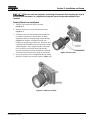
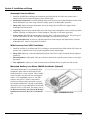
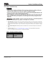
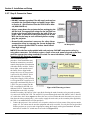
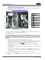
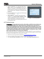
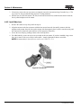
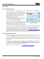
Section 5: Troubleshooting
5.3.2 Calibrate the ILS
The ILS must be calibrated when:
• a new lens has been installed
To calibrate the ILS, click the Full Calibration button. NOTE: If the Full Calibration button is selected when
Enable Automatic ILS is NOT selected, the lens will return to the remembered setting.
5.4
TPC
1. If the TPC fails to initialize, re-boot the projector.
2. A failed TPC usually indicates a system failure requiring service.
3. If the TPC display is blank, ensure the TPC is on by opening the flap at the back of the TPC and verify the
grey button in the bottom left corner is ON.
4. If the locations of button presses on the screen seem to be misinterpreted, the TPC screen may need
recalibrating. In the Administrator Setup: Preferences window, click the Calibrate Screen button and
follow the onscreen instructions.
5.5
Ethernet
5.5.1 Trouble Establishing Communication with Projector
Ensure Ethernet settings are valid for the site. All devices should have the same subnet mask yet unique IP
addresses.
5.6
Displays
Some of the following troubleshooting entries assume the use of a third-party input source for displaying
alternative “non-cinema” material. Before proceeding, ensure to consult the documentation supplied with the
external equipment.
5.6.1 Blank Screen, No Display of Cinema Image
1. Ensure the lens cap is not on either end of the lens.
2. Ensure the lamp is ON.
3. Confirm all power connections are still OK.
4. Ensure the douser is OPEN by verifying the state of the douser on Main panel.
5. Ensure any test pattern other than the full black test pattern displays properly.
6. Is the correct display file selected?
7. Is the correct cinema port connected for this display file (i.e., 292-A or 292-B)? Check connections.
5-4
CP2210 Setup Guide
020-100524-02 Rev. 1 (11-2010)
Section 5: Troubleshooting
5.6.2 Severe Motion Artifacts
Most likely there is a synchronization problem with reversed 3-2 pull-down in 60Hz-to-24Hz film-to-digital
conversion in your source. The display file needs correction.
5.6.3 Image Appears Vertically Stretched or ‘Squeezed’ into Center of Screen
Source data converted from film and “pre-squeezed” for the CP2210 display format may require use of an
anamorphic lens (or resizing) to regain full “scope” image width and proper proportions. Verify the Resolution
and Aspect Ratio settings in the Advanced Setup: Source File Setup window as well as the Lens Factor in the
Advanced Setup: Screen File Setup window.
5.6.4 No Image, Just a Black Screen
This problem is due to link encrypted cinema content not receiving the appropriate cryptographic key
information from the source cinema server.
1. Ensure the projector’s security lid is not unlocked or opened. A warning will display on the TPC. In the
event it is, close and lock the lid, and pause or stop the show on the server. Then, press Play on the server
and wait several seconds for the projector to receive the set of decrypting keys (from the server). If after 30
seconds the projector does not recover, pause or stop the show and try playing again. If this doesn’t work,
try resetting the server.
2. Check the Status window on the TPC for a tamper warning. If the lamp door is closed, the tamper switch
may be faulty.
3. Ensure the IP octets for the projector and the server match. Change if necessary.
5.6.5 No Image, Just Pink Snow
If you are running Cinema content, make sure the LD Bypass check box on the Channel Setup page is NOT
selected for the specific channel you are using. All encrypted content must pass through the Enigma for proper
playback.
5.6.6 Colors in the Display are Inaccurate
The color, tint, color space and/or color temperature settings may require adjustment at your input source or in
the Channel Setup: Config 2 window. Ensure the correct PCF, TCGD and Color Space file for the source
are used.
5.6.7 Display is Not Rectangular
1. Check the leveling of the projector. Ensure the lens surface and screen are parallel to one another.
2. Check the vertical offset. Adjust as necessary using the vertical offset knob or ILS.
3. Check that the anamorphic lens is straight. Rotate to orient aperture correctly.
4. Check the screen file. For more information, refer to Section 3 - Operation from the CP2210 User Manual
(020-100410-01).
CP2210 Setup Guide
020-100524-02 Rev. 1 (11-2010)
5-5
Section 5: Troubleshooting
5.6.8 Display is “Noisy”
1. Display adjustment at your input source may be required. From a DVD player or an input module setting,
adjust pixel tracking, phase and filter. Noise is particularly common on YPbPr signals from a DVD player.
2. The video input may not be terminated. Ensure the video input is terminated (75 ohms). If it is the last
connection in a loop-through chain, the video input should be terminated at the last source input only.
3. The input signal and/or signal cables carrying the input signal may be of poor quality.
4. If the distance between the input source device and the projector is greater than 25 feet, signal amplification/conditioning may be required.
5. If the source is a VCR or off-air broadcast, detail may be set too high.
5.6.9 Display has Suddenly Frozen
If the screen blacks out inexplicably, it is possible that excessive voltage noise on the AC or ground input has
interrupted the projector's ability to lock on to a signal. Power down the projector and then power back up
again.
5.6.10 Data is Cropped from Edges
To display the missing material, reduce image size to fill the display area available in the projector, then stretch
vertically to fill the screen from top to bottom. Add the anamorphic lens to regain image width. Cropping could
also be due to the screen file selected that has cropping configured.
5.6.11 The Projector is ON, but There is No Display
1. Ensure AC power is connected.
2. Make sure the lens cover is removed from the lens.
3. Make sure the douser is OPEN.
4. If the lamp is not ignited, click the LAMP ON button. If the lamp does not strike, refer to 5.2.1 Lamp Does
Not Ignite, on page 5-2. Ensure the correct channel is selected with the appropriate configurations in the
Channel Setup: Config 1 window.
5. Is an active source connected properly? Check the cable connections and make sure the alternative source
is selected.
6. Can you access test patterns? If so, check your source connections again.
7. Ensure your Cinema server is running Series 2 compatible software.
5.6.12 The Display is Jittery or Unstable
1. If the non-cinema display is jittery or blinking erratically, ensure that the source is properly connected and
is offering adequate quality for detection. With a poor quality or improperly connected source, the
projector will repeatedly attempt to display an image, however briefly.
2. The horizontal or vertical scan frequency of the input signal may be out of range for the projector. Refer to
Section 6 - Specifications from the CP2210 User Manual (020-100410-xx) for scan frequency ranges.
3. The sync signal may be inadequate. Correct the source problem.
5-6
CP2210 Setup Guide
020-100524-02 Rev. 1 (11-2010)
Section 5: Troubleshooting
5.6.13 The Display is Faint
1. The source may be double terminated. Ensure the source is terminated only once.
2. The source (if non-video) may need sync tip clamping.
5.6.14 The Upper Portion of the Display is Waving, Tearing or Jittering
This can occur with video or VCR sources. Check your source.
5.6.15 Portions of the Display are Cut OFF or Warped to the Opposite Edge
Resizing may need adjustment. Adjust until entire image is visible and centered. For more information, refer to
Section 3 - Operation from the CP2210 User Manual (020-100410-xx).
5.6.16 Display Appears Compressed (Vertically Stretched)
1. The frequency of the pixel sampling clock is incorrect for the current source.
2. Sizing and positioning options may be adjusted poorly for the incoming source signal.
3. Use an anamorphic lens for typical HDTV and anamorphic DVD sources that have been re-sized and
vertically stretched, via 3rd-party software.
5.6.17 Display Quality Appears to Drift from Good to Bad, Bad to Good
1. The source input signal may be of low quality.
2. The H or V frequency of the input may have changed at the source end.
CP2210 Setup Guide
020-100524-02 Rev. 1 (11-2010)
5-7
Corporate offices
Worldwide offices
USA – Cypress
ph: 714-236-8610
United Kingdom
ph: +44 118 977 8000
Hungary/Eastern Europe
ph: +36 (0) 1 47 48 100
Beijing
ph: +86 10 6561 0240
Canada – Kitchener
ph: 519-744-8005
Germany
ph: +49 2161 664540
Singapore
ph: +65 6877 8737
Korea
ph: +82 2 702 1601
France
ph: +33 (0) 1 41 21 44 04
Shanghai
ph: +86 21 6278 7708
Japan
ph: +81 3 3599 7481
For the most current technical documentation, please visit www.christiedigital.com