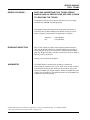
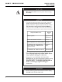
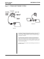
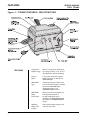
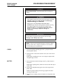
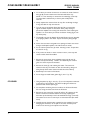
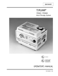
1
®
T/PUMP
®
REF TP472
Heat Therapy System
SERVICE MANUAL
P/N 11205-000 5/01
SERVICE MANUAL
TP472 T/PUMP
BEFORE YOU BEGIN . . .
READ AND UNDERSTAND THIS T/PUMP SERVICE
MANUAL AND ALL PRECAUTIONS (SEE PAGE 2) PRIOR
TO SERVICING THE T/PUMP.
The purpose of this manual is to provide operation, service, and repair
information for GAYMAR heat therapy pumps.
Only qualified medical service personnel should repair the T/Pump, in
accordance with the TP472 T/Pump Service Manual. Contact your local
dealer or Gaymar's Technical Service Department for assistance.
RECEIVING INSPECTION
Telephone:
(716) 662-8636
Fax:
(716) 662-0730
Upon receipt, unpack the T/Pump. Save all packing material. Perform a
visual and mechanical inspection for concealed damage. If any damage is
found, notify the carrier at once and ask for a written inspection. Photograph any damage and prepare a written record. Failure to do so within 15
days may result in loss of claim.
Contact your local dealer for assistance.
WARRANTIES
The TP472 T/Pump is warranted free of defects in material and
workmanship for a period of one (1) year, under the terms and conditions
of the Gaymar warranty in place at the time of purchase. A copy of the
warranty is available upon request. Gaymar disclaims all implied warranties
including, but not limited to, the implied warranties of merchantability and
of fitness for a particular purpose.
T/PUMP, T/PAD, Mul•T•Pad, and Clik-Tite are registered in U. S. Patent and Trademark Office. U. S. PATENT 4,068,870
© 2001. Gaymar Industries, Inc. All rights reserved. www.gaymar.com
SERVICE MANUAL
TP472 T/PUMP
CONTENTS
SAFETY PRECAUTIONS .......................................................... 2
CONTENTS
INTRODUCTION ....................................................................... 3
FEATURES .................................................................................. 4
SPECIFICATIONS ...................................................................... 5
THEORY OF OPERATION ....................................................... 6
STORAGE / CLEANING ............................................................ 8
FUNCTIONAL CHECK AND SAFETY INSPECTION ......... 9
INSPECTION FORM ................................................................ 14
DISASSEMBLY / REASSEMBLY ............................................. 15
CALIBRATION ......................................................................... 18
TROUBLESHOOTING ............................................................ 20
REPLACEMENT PARTS LISTS .............................................. 26
ILLUSTRATIONS
1
T/PUMP® HEAT THERAPY SYSTEM ...................................... 3
2
T/PUMP FEATURES/SPECIFICATIONS ................................ 4
3
T/PUMP COMPONENTS .......................................................... 7
4
MOTOR ...................................................................................... 10
5
TPC1 TEST COVER ................................................................. 21
6
FUNCTIONAL CHECK TEST DIAGRAM ............................ 22
7
CIRCUIT DIAGRAM FOR T/PUMP ....................................... 23
8
CIRCUIT DIAGRAM FOR TPC1 TEST COVER ................... 24
9
EXPLODED VIEW OF T/PUMP ............................................. 25
10 PC BOARD ASSEMBLY........................................................... 29
1
SERVICE MANUAL
TP472 T/PUMP
SAFETY PRECAUTIONS
DANGER
• Risk of electric shock. Disconnect power before servicing
the T/Pump.
WARNING
• This device pumps warmed water through a pad. Set pad temperature only as prescribed by and under the guidance of a
physician. Monitor the patient's temperature and skin condition
every 20 minutes or as directed by a physician. Failure to
adhere to these warnings could result in patient injury.
The following Groups/Conditions require additional surveillance:
dêçìéL`çåÇáíáçå=~í=êáëâ
mçíÉåíá~ä
áåàìêó
mÉÇá~íêáÅ=é~íáÉåíë
eóéÉêíÜÉêãá~L
ÜóéçíÜÉêãá~
m~íáÉåíë=ïáíÜ=áãé~áêÉÇ=ÅáêÅìä~íáçå
fëÅÜÉãá~
^êÉ~ë=çÑ=~ééäáÅ~íáçå=~êÉ=ìåÇÉê=éêÉëëìêÉ
fëÅÜÉãá~
få=ÅçãÄáå~íáçå=ïáíÜ=íçéáÅ~ä=ëçäìíáçåë
ïÜçëÉ=íçñáÅáíó=ã~ó=ÄÉ=~ÑÑÉÅíÉÇ=Äó=íÜÉ
~ééäáÅ~íáçå=çÑ=ÜÉ~í
`ÜÉãáÅ~ä
áåàìêó
få=ÅçãÄáå~íáçå=ïáíÜ=çíÜÉê=ÜÉ~í=ëçìêÅÉë
qÜÉêã~ä=áåàìêó
• Only qualified medical service personnel should repair the
T/Pump. Improper repair may result in death or serious
injury, equipment damage, or malfunction.
• Always perform the FUNCTIONAL CHECK AND SAFETY
INSPECTION (pp. 9-13) after making repairs and before returning
the T/Pump to patient use. Document your findings on the
INSPECTION FORM (p. 14). Improper repair may result in
death or serious injury, equipment damage, or
malfunction.
CAUTION
• Do not perform any powered tests with the reservoir empty.
Damage to the T/Pump may result.
2
SERVICE MANUAL
TP472 T/PUMP
INTRODUCTION
Figure 1 - T/PUMP HEAT THERAPY SYSTEM
Multiple Pads
Single Pad
The Gaymar T/Pump Heat Therapy System provides a means of applying
heat therapy by supplying temperature-controlled water through a
connector hose to a Gaymar T/Pad®. The hose is terminated in easy-touse Clik-Tite® connectors.
The T/Pad provides the interface for delivering the heat therapy. The
unique button design allows water to flow and provides trouble-free
operation when the pad is folded. The pads are applied to the part of the
body requiring heat therapy, and the circulating water maintains the pad
at the set point temperature.
The T/Pads can be interconnected to provide therapy to more than one
body site at a time.
3
FEATURES
SERVICE MANUAL
TP472 T/PUMP
Figure 2 - T/PUMP FEATURES / SPECIFICATIONS
FEATURES
4
Temperature
Setpoint Range
30-41°C, exiting water temperature
from pump; accuracy, ±1°C at 41°C.
Key-operated to prevent tampering.
Tip-over
Switch
Turns heater off if pump is tipped.
NOTE: This does not activate the
OVER TEMP light.
OVER TEMP
Light
Indicates the pump and heater have
been turned off. This light is activated
by the two OVER TEMP safety
thermostats. Refer to the
TROUBLESHOOTING section.
OVER TEMP
Safety
Thermostats
Either of two limit thermostats will
shut off pump and heater if
the high temperature limit is
exceeded. The OVER TEMP light will
glow. Refer to TROUBLESHOOTING
section.
Operating
Water Level
Indicator
Clear window allows viewing of the
reservoir water level.
SPECIFICATIONS
SERVICE MANUAL
TP472 T/PUMP
SPECIFICATIONS
Reservoir capacity
1500 ml maximum
Detachable
power cord
Use only an international
(harmonized) 3-wire cordset
using cordage approved to
HD-21 conductor size
1.00 mm2
Fuses
5x20 mm, 1.6A, Type “T”
Sheet 111
Voltage
~220-240
Frequency
50 Hz
Current
1.6A
Ambient operating
temperature
15.6°C to 32.2°C
Classification
Type B, Class 1, grounded
equipment suitable for
continuous operation. Not
classified for protection against
harmful ingress of liquid.
IPXO
Equipment not suitable for
use in the presence of a
flammable anaesthetic mixture
with air or with oxygen or
nitrous oxide.
5
THEORY OF OPERATION
WATER TEMPERATURE
CONTROL
SERVICE MANUAL
TP472 T/PUMP
There are four devices that control the operation of the heater in the
GAYMAR T/Pump:
• The temperature controller is thermistor actuated (fig. 3, item 1, p. 7).
This controller is adjustable over a temperature range of 30°C to 41°C.
The desired water temperature is set with a special removable key (fig.
3, item 3). To prevent unauthorized temperature setting changes,
remove the key after the temperature has been set.
• The manifold backup limit thermostat (fig. 3, item 8) is mounted on the
brass manifold block (fig. 3, item 7). This thermostat senses water
temperature flowing to the pad and will shut off the pump and heater
and activate the OVER TEMP light if the water temperature exceeds
specific limits. The purpose of the manifold backup limit thermostat is to
prevent the pump from providing water at too high a temperature to
the pad.
• The well backup limit thermostat (fig. 3, item 5) is mounted on the brass
plate (fig. 3, item 10) that extends along and under the heater (fig. 3,
item 4) near the bottom of the reservoir. This thermostat senses water
temperature in the reservoir and will shut off the pump and heater and
activate the OVER TEMP light if the reservoir temperature exceeds
specific limits. The purpose of the well backup limit thermostat is to
both prevent the pump from providing water at too high a temperature
to the pad and to protect the pump from high temperature damage due
to a low water level.
• The tip-over switch (fig. 3, item 2; see also fig. 10, item 4, p. 29) is
mounted on the PC board. This mercury-type switch will shut off the
heater if the pump is tipped more than 45° from the vertical position.
NOTE: The tip-over switch does not shut off the pump
motor or activate the OVER TEMP light.
FLUID SYSTEM
The pump (fig. 3, item 11, p. 7) is a sump configuration driven by an
impedance protected, shaded pole AC motor (fig. 3, item 6).
The return hose fitting (fig. 3, item 9) is machined internally to act as an
orifice. This maintains a back pressure in the pad to make it resistant to
flow restrictions.
6
T/PUMP COMPONENTS
SERVICE MANUAL
TP472 T/PUMP
FIGURE 3 - T/PUMP COMPONENTS
TOP
[10]
[11]
BOTTOM
7
SERVICE MANUAL
TP472 T/PUMP
STORAGE / CLEANING
Storage (Short term)
Disconnect pad. Connect ends of the connector hoses together. Open
hose clamps. Leave water in the reservoir. To prevent hose kinks, coil the
hose rather than folding it. Fasten the hose and cord with strap.
Storage (Long term)
Disconnect pad. Connect ends of the connector hose together. Open hose
clamps. Add 1/4 ounce GAYMAR catalog REF MTA33 germicidal or
equivalent to water already in reservoir. Run for two (2) minutes. Drain
pump. To prevent hose kinks, coil the hose rather than folding it. Fasten
the hose and cord with strap and store pump.
Draining
Disconnect the T/Pump from AC power. Disconnect the pad or hoses
from one another, keeping hoses at or above the level of the T/Pump.
Remove the fill cap and invert the T/Pump over a sink. When all fluid has
drained from the hoses and reservoir, replace the fill cap and connect the
hoses together.
Cleaning
Unplug the T/Pump prior to cleaning.
To clean the external surfaces, use a non-abrasive cleaning solution (such
as warm soapy water) and a damp cloth.
To clean the fluid system, drain the pump. Fill the reservoir to the operating level indicated on the side of the pump. Add 1/4 ounce GAYMAR
catalog REF MTA33 germicidal or equivalent. Set the temperature indicator
to its lowest setting (fully counterclockwise). Start the T/Pump and
circulate the solution for one hour. Drain the solution and refill the pump
with distilled water. Using distilled water retards algae growth and mineral
buildup.
Change the distilled water monthly or more often depending upon use.
Pads / Accessories
For best results use only GAYMAR T/Pads® or Mul•T•Pads®. The unique
button design allows water to flow and provides trouble free operation
when the pad is folded. This reduces the number of different sizes of pads
your facility must keep in inventory. The T/Pads can be interconnected to
provide therapy to more than one body site at a time (see fig. 1, p.3). For a
brochure listing the various T/Pads, contact your local GAYMAR dealer.
An optional bed bracket (model TP20A) is available to mount the T/Pump
on the footboard of a bed.
8
SERVICE MANUAL
TP472 T/PUMP
FUNCTIONAL CHECK &
SAFETY INSPECTION
FUNCTIONAL CHECK
This section is designed to provide a complete check of all pump parameters. The order of tests should be followed so that the functional testing
can be completed in the least possible time.
Follow the FUNCTIONAL CHECK AND SAFETY INSPECTION procedures
carefully, paying particular attention to test setups. Any deviation from the
setups, procedures, or test equipment may result in incorrect or misleading results.
Before making any repairs, be sure to recheck your test setup, procedure,
and test equipment.
DANGER
Risk of electric shock. Disconnect power before servicing the
T/Pump.
WARNING
• Only qualified medical service personnel should repair the T/Pump.
Improper repair may result in death or serious injury,
equipment damage, or malfunction.
• Always perform the FUNCTIONAL CHECK AND SAFETY INSPECTION
after making repairs and before returning the T/Pump to patient
use. Document your findings on the INSPECTION FORM
(p. 14). Improper repair may result in death or serious
injury, equipment damage, or malfunction.
CAUTION
Do not perform any powered tests with the reservoir empty.
Damage to the T/Pump may result.
INTERVAL
To assure the optimum performance, dependability and safety, the
following should be performed once a year (or as specified in the
facility's preventive maintenance program) and after making repairs.
REQUIRED TOOLS
TPT9 ------------------------- GAYMAR Flow and Temperature Tester
TFC1 ------------------------- Thermometer, -2°C to 52°C, 1°C accuracy,
30 cm long, 7.5 cm immersion
T/Pad ------------------------- Any GAYMAR “12” or “22” series T/Pad
TPC1 ------------------------- GAYMAR T/Pump Test Cover
Ground Resistance Tester
Current Leakage Meter
Distilled Water ------------- 2 liters (approximate)
Synthetic Oil ---------------- Anderol 465 (GAYMAR P/N 77137-000)
INSPECTION FORM -------- (p. 14)
9
SERVICE MANUAL
TP472 T/PUMP
FUNCTIONAL CHECK
1. PHYSICAL CONDITION
CHECK
1. Examine the line cord along its entire length for physical damage, such
as cuts or cracked insulation. A damaged line cord should be replaced
rather than repaired.
2. Operate switches and control settings at all positions. If defective,
replace.
3. Visually inspect pump. Check for cracked or damaged plastic parts.
Be sure unit is unplugged. Remove retainer cap. Remove four (4)
screws holding cover and remove cover. (Be sure not to lose fill neck
gasket.) Perform visual inspection of all internal parts. Remove any
accumulated dirt with a vacuum cleaner or compressed air hose. Leave
cover off for balance of inspection.
4. Check Clik-Tite connectors for cracks or missing O rings. Replace
connectors if necessary.
2. MOTOR LUBRICATION
1. Locate the motor manufacturer's ID on the top bearing housing.
If the pump motor is by Jakel, no oiling is required. If the pump motor
is by Uppco, proceed with the following oiling instructions.
2. Oil the pump motor every 6 months with Anderol #465 (GAYMAR
P/N 77137-000) or equivalent to extend the life of the T/Pump motor.
Do not use a petroleum-based oil since it will leave a residue as it
breaks down, causing the motor to seize. Add four (4) drops of oil to
the bearing housing of the motor located below the fan. Using a micro
oiler, apply a similar amount to the lower bearing at the location
indicated in figure 4.
NOTE: Early versions of
the pump motor have an
oiler tube which does
not effectively distribute
oil to the lower bearing.
Do not use the oiler
tube to apply oil to the
lower bearing. Use a
micro oiler to apply oil
directly to the locations
shown in figure 4.
Figure 4 - PUMP MOTOR
10
SERVICE MANUAL
TP472 T/PUMP
3. TPC1 TEST COVER
INSTALLATION
FUNCTIONAL CHECK
1. When connecting the test cover do not remove any wiring connections
in the T/Pump. Simply clip the test cover alligator clips onto terminals
with the same color wire.
2. Connect TPC1 test cover (see fig. 5, p. 21 and fig. 8, p. 24). Always
match the color of TPC1 wiring connections to the color of
T/Pump wiring. Be sure to keep wires away from fan. Install test cover.
Be sure to push cover on tightly. It is not necessary to install screws.
3. Connect pump with test cover, pad and TPT9 flow/temp tester (see fig.
6, p. 22). Be sure the TPT9 is connected to the supply side of the
T/Pump, before the pad.
4. Fill unit with room temperature distilled water and replace fill cap.
Connect any “12” or “22” series T/Pad. Place pad on an insulating
material (e.g., cloth or towel).
5. Set both test cover switches to the OPEN position.
4. GROUND RESISTANCE
CHECK
DANGER
Risk of electric shock. Be sure unit is unplugged when performing
ground resistance test.
1. Use a ground resistance meter to measure the resistance between the
ground pin on the power entry module (fig. 9, item 40, p. 25) and the
brass manifold block (fig. 9, item 45). Contact is available through the
hole where the hoses connect to the pump. This value should not be
more than 0.5 ohm.
5. CURRENT LEAKAGE
CHECK
It will be convenient to check current leakage at this point since the unit is
full and connected to a pad.
1. Measure the maximum current leakage in all combinations of heater
“ON” or “OFF” and power switch “ON” or “OFF.” Access to chassis
ground for current leakage testing is available through the hole where
the hose connects to the pump. The highest reading is typically less
than 30 microamperes. The maximum allowable reading is 100
microamperes. Record the highest reading.
2. Disconnect leakage meter setup.
6. TIP-OVER SWITCH
CHECK
1. Check the tip-over switch at this point, since the test cover is on
and the unit is full. Set temperature to maximum (41°C) on dial.
The heater indicator (fig. 5, p. 21) will be on. Tip the unit approximately 45°. If the heater indicator goes out, the tip-over switch is
operating. If not, repair or replace the PC board (p. 16). Record
results.
11
FUNCTIONAL CHECK
7. FLOW RATE TEST
SERVICE MANUAL
TP472 T/PUMP
1. Be sure the pad is flat and warm (approximately 41°C) and at the same
level as the pump. Top of TPT9 float (see fig. 6, p. 22) should read at
least 30 lph. Record reading.
NOTE: If flow is below 30 lph, refer to TROUBLESHOOTING section
(p. 20).
8. OPERATING
TEMPERATURE TEST
1. Make sure temperature is set to maximum (41°C) on dial. Allow unit to
come to a steady temperature, approximately thirty (30) minutes.
2. To ensure accurate temperature readings, add a small amount of water
to TPT9 well. Insert thermometer in TPT9 well.
3. Take readings every thirty (30) seconds for five (5) minutes for a total
of ten (10) readings. The average of these readings should be 41°C
±1°C. Record the average value. If the unit is out of calibration, refer to
CALIBRATION section (p. 18).
4. Do not let the pump cool down. Proceed directly to Backup Limit
Thermostat Test.
9. BACKUP LIMIT
THERMOSTAT TEST
1. With the pump operating properly at 41°C ±1°C, move the primary
shorting switch to the SHORT position (see fig. 5, p. 21). This will short
out the temperature controller and allow the pump to continue heating
to the trip point of the backup limit thermostat(s).
2. Carefully observe the rising temperature and record the highest
reading. When a thermostat opens, the pump will turn off, the OVER
TEMP light will be lit, and the HEATER INDICATOR light on the test
cover will turn off. (If the OVER TEMP light does not light and a thermostat has tripped, replace the light.) Either the MANIFOLD or WELL light
on the test cover will be lit or both lights will be off, depending on
which thermostats have tripped.
• If the manifold thermostat light is on, then the manifold thermostat
has opened. The temperature recorded must be between 43.3°C to
47.2°C. If the thermostat operates outside its intended
range, it must be replaced (see page 17). Proceed to step 3,
p.13.
• If the well thermostat light is on, then the well thermostat has
opened. The temperature recorded must be between 43.3°C to
50°C. If the thermostat operates outside its intended range,
it must be replaced (see page 17). Proceed to step 3, p 13.
• If neither light is on, then both thermostats have opened at the same
temperature. To confirm this, toggle the thermostat shorting switch
to the MANIFOLD position. (The MANIFOLD light should be on.)
Next, toggle switch to the WELL position. (The WELL light should be
on.) If either thermostat opens outside its intended range as
defined above, it must be replaced (see page 17). Proceed to
step 4, p. 13.
12
SERVICE MANUAL
TP472 T/PUMP
FUNCTIONAL CHECK
3. To test the remaining thermostat, toggle the limit thermostat shorting
switch to the position corresponding to the non tripped thermostat.
(This will short out the previously opened thermostat and allow the
unit to continue heating.) Both thermostat indicator lights should be off
and the HEATER INDICATOR light should be on. Carefully observe the
rising temperature and record the highest reading. When the water
temperature rises to the trip point of the remaining thermostat, the
OVER TEMP light will be on, the pump will turn off, the heater indicator
light will turn off, and the appropriate thermostat light will be on.
• If the manifold thermostat light is on, then the manifold thermostat
has opened. The temperature recorded must be between 43.3°C
to 47.2°C. If the thermostat operates outside its intended
range, it must be replaced (see page 17).
• If the well thermostat light is on, then the well thermostat has
opened. The temperature recorded must be between 43.3°C to
50°C. If the thermostat operates outside its intended
range, it must be replaced (see page 17).
4. Unplug the unit, remove the test cover and proceed to LEAK TEST.
10. LEAK TEST
1. Immediately upon completion of Backup Limit Thermostat Test,
reinstall fill cap tightly. Put your finger over the hole in the cap and tilt
unit toward you so the front is down. Hold for three (3) minutes.
2. Return the unit to upright position and carefully check inside of tray
and reservoir tray joint for leaks. Repeat process turning pump on back
face. If leakage is found, refer to the DISASSEMBLY/REASSEMBLY section
(pp. 15-17), and correct problem.
11. COVER AND FILL
NECK GASKET
REINSTALLATION
When reinstalling cover, be sure the fill neck gasket (fig. 9, item 6, p. 25) is
in place. Push cover down as tightly as possible. Hold in place when
tightening cover screws.
This completes the FUNCTIONAL CHECK procedure. Return pump to
service if it is operating properly, or proceed to the DISASSEMBLY/
REASSEMBLY section pertaining to the problem(s).
13
INSPECTION FORM
Inspection forms vary from hospital to hospital. The
following sample form is intended as a guide so that the
important parameters are recorded.
14
SERVICE MANUAL
TP472 T/PUMP
SERVICE MANUAL
TP472 T/PUMP
DISASSEMBLY/REASSEMBLY
DANGER
Risk of electric shock. Disconnect power before servicing the
T/Pump.
WARNING
• Only qualified medical service personnel should repair the T/Pump.
Improper repair may result in death or serious injury,
equipment damage, or malfunction.
• Always perform the FUNCTIONAL CHECK AND SAFETY
INSPECTION (pp. 9-13) after making repairs and before returning
the T/Pump to patient use. Document your findings on the
INSPECTION FORM (p. 14). Improper repair may result in
death or serious injury, equipment damage, or
malfunction.
CAUTION
Do not perform any powered tests with the reservoir empty.
Damage to the T/Pump may result.
NOTE: All wires are terminated with slip-on connectors. When
text says “remove wire,” the slip-on connector is to be removed
from the mating lug on the specific item.
COVER
1.
Unscrew fill cap/valve assembly (fig. 9, item 1, p. 25) and remove.
Unscrew plastic retainer.
2.
Remove the four screws which retain the cover, two on each end of
the pump.
NOTE: When reinstalling the cover, do not forget to replace the fill
neck gasket (fig. 9, item 6).
MOTOR
1.
Place a screwdriver under fan hub (fig. 9, item 7, p. 25) and twist to
remove fan.
NOTE: When replacing the fan, make sure the hub is flush with top of
motor shaft.
2.
Remove green (w/yellow stripe) ground wire and orange and blue
power wires.
NOTE: To prevent breaking the motor lugs, support them when
removing the slip-on lugs.
3.
Remove the four retaining screws and washers on the top face of the
motor.
15
DISASSEMBLY/REASSEMBLY
SERVICE MANUAL
TP472 T/PUMP
4. It is necessary to remove the reservoir to remove the motor. Remove
the eight (8) screws located around the inside wall of the tray.
NOTE: It is not necessary to remove the front label (fig. 9, item 34).
The front label is attached only to the tray and will slip off the
reservoir.
5. Gently separate the reservoir from the tray. Do not damage the large
O ring that seals the tray and reservoir.
6. Turn the tray on its backside (front label up). Place a screwdriver
against the white impeller in the bottom of the pump housing to
prevent the impeller from turning and remove the screw retaining the
impeller. It is not necessary to remove the bottom housing (fig. 9, item
21) of the pump.
7. The impeller may now be slipped off the shaft. Return the tray assembly
to an upright position. The motor may be removed by lifting straight
up.
8. Center the new motor seal gasket over opening and insert new motor
through seal. Replace impeller onto shaft and secure motor.
9. Do not overtorque the four (4) motor mounting screws. Torque value
is 6.9 to 9.2 cm-kg.
10. If tray inserts are loose or motor mounts are worn, a new tray with
sensor bracket should be installed.
HEATER
1. Remove the ground wire (green w/yellow stripe) and the two (2)
heater wires (red and blue). NOTE: On reassembly, the red wire
goes on to the front post of the heater.
2. Remove the three (3) nuts retaining the heater. The screws are
retained in the tray. The heater can then be removed by raising and
tilting the top of the heater toward the left side of the T/Pump.
3. Reassembly is the reverse of the above.
4. Do not forget to install heater gasket (fig. 9, item 11, p. 25).
PC BOARD
1. Using the plastic key (fig. 3, item 3, p. 7), turn the temperature indicator
to the eleven o'clock position. The slotted coupling should then be
positioned with the slot opening up.
2. Cut the plastic tie holding the wire bundle to the PC board. Remove
the red, orange, and blue wires from the PC board.
3. Remove the two screws (fig. 9, items 53 & 54, p. 25) retaining the PC
board. The board can then be raised from the tray, exposing the
thermistor probe assembly in the brass manifold block (fig. 9, item 45).
Use caution to be sure no strain is put on thermistor leads (fine white
wires).
4. Carefully remove the thermistor capsule from the manifold. To avoid
damaging the thermistor, do not pull on the wires. A dental pick or
scribe can be used to pry the capsule out of the hole.
16
SERVICE MANUAL
TP472 T/PUMP
DISASSEMBLY/REASSEMBLY
5. On reassembly, put a small quantity of silicone heat sink compound
(Dow Corning #340 or equivalent) around the thermistor capsule.
Carefully insert the thermistor capsule into the hole on the brass
manifold block. To avoid damaging the thermistor, do not push on the
wires. The capsule may be seated by placing needle nose pliers or
tweezers on the edge of the capsule.
6. The remainder of the reassembly is the reverse of the above. Upon
inserting the P. C. Board, the potentiometer shaft (fig. 9, item 49) must
be in the vertical position to mate with the slot in the temperature
indicator (fig. 9, item 37). Refer to CALIBRATION procedures
(pp. 18-19).
MANIFOLD BACKUP
LIMIT THERMOSTAT
1. Remove the two (2) wire lugs. Note the position of the color coded
wires. Facing the front of the T/Pump, the purple wire goes on the left
hand lug, and the orange wire goes on the right hand lug.
2. Remove the two (2) screws retaining the thermostat to the brass
manifold block.
3. Reassembly is the reverse of the above.
4. Always be sure to check the backup limit thermostats according to the
FUNCTIONAL CHECK (pp. 12-13).
WELL BACKUP
LIMIT THERMOSTAT
TRAY
NOTE: Do not attempt to replace the well thermostat.
To insure proper operation of this thermostat, it is riveted and
sealed to the tray assembly. Experience has proven that it cannot be
successfully replaced. If this item is defective, replace the
entire tray assembly (fig. 9, item 15, p. 25).
1. Remove the eight (8) screws (fig. 9, item 14, p. 25) around the inside
wall of the tray. Gently pry the reservoir from the tray.
2. Remove all components including seal, bushing, and clips from the old
tray and reinstall into the new tray assembly.
3. Attach the reservoir to the tray. Check that the reservoir ring seal (fig.
9, item 16) is properly located in the groove in the tray. Install the eight
(8) screws torqued to approximately 6 cm-kg.
4. Always be sure to check the backup limit thermostats according to the
FUNCTIONAL CHECK (pp. 12-13).
17
SERVICE MANUAL
TP472 T/PUMP
CALIBRATION
DANGER
Risk of electric shock. Disconnect power before servicing the
T/Pump.
WARNING
• Only qualified medical service personnel should repair the T/Pump.
Improper repair may result in death or serious injury,
equipment damage, or malfunction.
• Always perform the FUNCTIONAL CHECK AND SAFETY
INSPECTION (pp. 9-13) after making repairs and before returning
the T/Pump to patient use. Document your findings on the
INSPECTION FORM (p. 14). Improper repair may result in
death or serious injury, equipment damage, or
malfunction.
CAUTION
Do not perform any powered tests with the reservoir empty.
Damage to the T/Pump may result.
CALIBRATION
EQUIPMENT
TPT9 ---------------------------- GAYMAR Flow and Temperature Tester
TPC1 ---------------------------- GAYMAR T/Pump Test Cover
TFC1 ---------------------------- Thermometer, -2°C to 52°C, 1°C accuracy,
30 cm long, 7.5 cm immersion
Insulated alignment tool
T/Pad ---------------------------- Any GAYMAR “12” or “22” series
The calibration should be performed in a temperature controlled room,
between 21°C and 24°C.
CALIBRATION
1. Remove the pump cover by removing the two (2) screws at each end
of the pump. The fill cap/valve assembly can be removed by unscrewing
the cap and plastic retainer. The cover is now free to be removed.
2. Carefully remove the vinyl seal from the R3 trim pot (fig. 10, item 3, p.
29), located at the top right corner of the printed circuit board.
3. Install test cover. See FUNCTIONAL CHECK (p. 11) and fig. 5, p. 21.
4. Connect pump, pad, and TPT9 Flow and Temperature Tester
according to fig. 6, p. 22.
18
SERVICE MANUAL
TP472 T/PUMP
CALIBRATION
5. Fill pump with room temperature distilled water.
6. Set Temp Dial to 41°C (maximum).
NOTE: Be sure the temperature dial is always set to the
maximum clockwise position when making calibration
measurements and adjustments.
7. The primary shorting switch (fig. 5) on the test cover must be in the
OPEN position. The backup limit thermostat shorting switch (fig. 5)
must be in the OPEN position.
8. Turn unit on and allow to come to a steady temperature, approximately thirty (30) minutes.
The HEATER INDICATOR on the cover should be on whenever the
heater is on.
NOTE: Flow must be 30 lph, minimum.
If not, refer to TROUBLESHOOTING (p. 20).
9.
Start recording the temperature readings every thirty (30) seconds for
five (5) minutes for a total of ten (10) readings. The average of these
readings should be 41°C ±1°C. If not, it will be necessary to adjust the
R3 trim pot (fig. 5). This is accomplished by inserting an insulated
alignment tool through the small hole in the left side of the TPC1 test
cover. Turn the potentiometer screw clockwise to increase the water
temperature. Turn the screw counterclockwise to decrease the water
temperature.
Do not force the adjusting screw past its stops.
10. After the final adjustment is made, let the unit run for one-half hour
and recheck the calibration as described in step 9. The bandwidth
should not exceed 1°C. Bandwidth is the difference between the
maximum and minimum temperature excursions. If the OVER TEMP
light is activated during the calibration adjustment, the water must be
replaced with water 24°C or less and the calibration procedure
repeated.
11. Without letting the pump cool, proceed directly to the Backup Limit
Thermostat Test as outlined in the FUNCTIONAL CHECK (pp. 12-13).
Record all results when recalibrating.
Apply new vinyl seal after the trim pot has been adjusted properly.
19
SERVICE MANUAL
TP472 T/PUMP
TROUBLESHOOTING
mol_ibj
?lsbo=qbjm?=äáÖÜí=áë=çåK
mlppf_ib=`^rpb
NK
OK
PK
QK
låÉ=çÑ=íÜÉ=Ä~Åâìé=äáãáí=íÜÉêãçëí~íë=Ü~ë=Ñ~áäÉÇK råéäìÖ=éìãé=~åÇ=áåëí~ää=~=íÉëí=ÅçîÉêK=aÉíÉêãáåÉ=ïÜáÅÜ
íÜÉêãçëí~í=Ü~ë=Ñ~áäÉÇK=oÉÑÉê=íç=_~Åâìé=iáãáí=qÜÉêãçëí~í
qÉëíë=EéK=NOFK=oÉéä~ÅÉ=íÜÉêãçëí~í=EéK=NTFK
RK
m`=Äç~êÇ=EíÉãéÉê~íìêÉ=ÅçåíêçääÉêF=Ü~ë=Ñ~áäÉÇK
råéäìÖ=éìãéI=áåëí~ää=íÉëí=ÅçîÉêI=~åÇ=éÉêÑçêã=`~äáÄê~íáçå
EééK=NUJNVFK=oÉéä~ÅÉ=m`=Äç~êÇ=~ë=êÉèìáêÉÇ=EééK=NSJNTFK
S
jçíçê=Ñ~áäÉÇ
oÉéä~ÅÉ=ãçíçêK
qLmìãé=ïáää=åçí=éìãéK
NK
lkLlcc=ëïáíÅÜ=éáäçí=äáÖÜí
áë=äáíK
OK
t~íÉê=äÉîÉä=áë=äçïI=çê=êÉëÉêîçáê=áë=ÉãéíóK
oÉÑáää=ïáíÜ=êççã=íÉãéÉê~íìêÉ=ÇáëíáääÉÇ=ï~íÉê=íç=éêçéÉê
äÉîÉäK
?lsbo=qbjm?=äáÖÜí=áë=çåK
oÉÑÉê=íç=?lsbo=qbjm?=ëÉÅíáçå=~ÄçîÉK
qLmìãé=ïáää=åçí=éìãéK
NK
lkLlcc=ëïáíÅÜ=éáäçí=äáÖÜí
ÇçÉë=åçí=äáÖÜíK
OK
qÜÉ=?lk?=ëïáíÅÜ=ã~ó=åçí=ÄÉ=Ñìääó=ÉåÖ~ÖÉÇK
qÜÉ=äáÖÜí=çå=íÜÉ=ëïáíÅÜ=ëÜçìäÇ=ÄÉ=äáíK=sÉêáÑó=íÜ~í=íÜÉ
ëïáíÅÜ=áë=Ñìääó=ÉåÖ~ÖÉÇ=áå=íÜÉ=?lk?=éçëáíáçåK
mçïÉê=ÅçêÇ=áë=åçí=Ñìääó=áåëÉêíÉÇ=áåíç=éçïÉê
Éåíêó=ãçÇìäÉ=çê=ÖêçìåÇÉÇ=êÉÅÉéí~ÅäÉK
fåëÉêí=íÜÉ=éäìÖ=Ñìääó=áåíç=íÜÉ=êÉÅÉéí~ÅäÉ=~åÇ=éçïÉê=Éåíêó
ãçÇìäÉK
PK
cìëÉ=áë=ÄäçïåK
fåëéÉÅí=Ñçê=ÄêçâÉå=çê=ÇáëÅçååÉÅíÉÇ=áåíÉêå~ä=ïáêáåÖK
`ÜÉÅâ=Ñçê=ëÜçêíÉÇ=ÅçãéçåÉåíëK
QK
a~ã~ÖÉÇ=ÅçêÇ=çê=éäìÖK
`ÜÉÅâ=éäìÖ=íÉêãáå~äëK=`ÜÉÅâ=éçïÉê=ÅçêÇ=Åçåíáåìáíó=íç
ÄêÉ~âÉêK====klqbW=cäÉñ=ÅçêÇ=ïÜáäÉ=ÅÜÉÅâáåÖ=ÅçåíáåìáíóK
oÉéä~ÅÉ=éçïÉê=ÅçêÇ=~ëëÉãÄäó=~ë=êÉèìáêÉÇK
NK
råáí=áë=íáééÉÇK
mä~ÅÉ=ìåáí=çå=äÉîÉä=ëìêÑ~ÅÉK
OK
eÉ~íÉê=áë=åçí=êÉÅÉáîáåÖ=éçïÉêI=çê=áë=ÇÉÑÉÅíáîÉK
`ÜÉÅâ=áÑ=ëÉíéçáåí=Ü~ë=ÄÉÉå=ëÉí=íçç=äçïK=oÉãçîÉ=ÅçîÉê
~åÇ=ÅÜÉÅâ=éçïÉê=íç=ÜÉ~íÉêK=fÑ=éçïÉê=áë=éêÉëÉåíI=ÜÉ~íÉê
áë=éêçÄ~Ääó=ÇÉÑÉÅíáîÉK=`çäÇ=ÜÉ~íÉê=êÉëáëí~åÅÉ=áë
~ééêçñáã~íÉäó=NRR=çÜãëK=oÉéä~ÅÉ=áÑ=êÉèìáêÉÇK=fÑ=íÜÉêÉ=áë
åç=éçïÉê=~í=ÜÉ~íÉê=íÉêãáå~äëI=êÉéä~ÅÉ=m`=Äç~êÇK
PK
?lsbo=qbjm?=äáÖÜí=áë=çåK
oÉÑÉê=íç=?lsbo=qbjm?=ëÉÅíáçå=~ÄçîÉK
qLmìãé=éìãéë=lhI=Äìí
NK
lkLlcc=ëïáíÅÜ=éáäçí=äáÖÜí
ÇçÉë=åçí=äáÖÜíK
lkLlcc=ëïáíÅÜ=ÇÉÑÉÅíáîÉK
oÉéä~ÅÉ=lkLlcc=ëïáíÅÜK
klqbW==kÉçå=éáäçí=äáÖÜí=áë=åçí=êÉéä~ÅÉ~ÄäÉK
cäçï=ê~íÉ=áë=äÉëë=íÜ~å
PM=äéÜK
NK
cäçï=é~íÜ=áë=êÉëíêáÅíÉÇ=çê=çÄëíêìÅíÉÇK
_É=ëìêÉ=éìãé=áë=~í=ë~ãÉ=äÉîÉä=~ë=é~ÇI=é~Ç=áë=Ñä~íI=~åÇ
ï~íÉê=íÉãéÉê~íìêÉ=áë=QNø`K=Ecäçï=áë=ëéÉÅáÑáÉÇ=ìåÇÉê
íÜÉëÉ=ÅçåÇáíáçåëKF=iççâ=Ñçê=çÄëíêìÅíáçåë=áå=íÜÉ=Ñäçï
é~íÜK=léÉå=ÜçëÉ=Åä~ãéëK=qÜÉ=çêáÑáÅÉ=áå=íÜÉ=êÉíìêå=ÜçëÉ
ÑáííáåÖ=EÑáÖK=VI=áíÉã=QPI=éK=ORF=áë=íÜÉ=ëã~ääÉëí=ÜçäÉK
OK
jçíçê=áë=ã~äÑìåÅíáçåáåÖK
pÉÉ=@N=~ÄçîÉK=fÑ=Ñäçï=é~íÜ=áë=ÅäÉ~êI=êÉéä~ÅÉ=ãçíçêK
`ìêêÉåí=äÉ~â~ÖÉ=áë=íçç
ÜáÖÜK
NK
eÉ~íÉê=ïáää=ÄÉ=íÜÉ=ãçëí=éêçÄ~ÄäÉ=Å~ìëÉK
aáëÅçååÉÅí=ÜÉ~íÉê=~åÇ=ÅÜÉÅâ=~Ö~áåK=oÉéä~ÅÉ=ÜÉ~íÉê=áÑ
åÉÅÉëë~êóK=fÑ=ÅìêêÉåí=äÉ~â~ÖÉ=êÉã~áåë=ÜáÖÜI=ÅçåíáåìÉ
ÇáëÅçååÉÅíáåÖ=ÅçãéçåÉåíë=ìåíáä=Ñ~ìäí=áë=äçÅ~íÉÇK
oÉëáëí~åÅÉ=íç=ÖêçìåÇ
Ñ~áäìêÉ=EÖêÉ~íÉê=íÜ~å
MKR=çÜãF
NK
b~êíÜ=ÅçåÇìÅíçê=ÅçååÉÅíáçåë=ïáíÜáå=éìãéK
`ÜÉÅâ=íÜ~í=ÅçååÉÅíáçåë=~êÉ=íáÖÜíK=fÑ=éêçÄäÉã=éÉêëáëíëI
ÅÜÉÅâ=ÖêçìåÇáåÖ=ïáêÉ=íç=É~ÅÜ=ÅçãéçåÉåí=Ñçê=ÅçåíáåìáíóK
t~íÉê=äÉ~âë=Ñêçã
`äáâJqáíÉ=ÅçååÉÅíçêK
qÜÉ=qLmìãé=ãìëí=~äï~óë=ÄÉ=ÅçååÉÅíÉÇ=íç=~=qLm~Ç=çê=íÜÉ=ÜçëÉ=ÉåÇë=ãìëí=ÄÉ=àçáåÉÇ
íçÖÉíÜÉê=íç=éêÉîÉåí=ï~íÉê=Ñäçï=äÉ~â~ÖÉK=fÑ=íÜÉ=ÅçååÉÅíçê=äÉ~âëI=ÅÜÉÅâ=ÑçêW
qLmìãé=éìãéë=lhI=Äìí
ïáää=åçí=ÜÉ~íK
20
objbav
m~Ç=çê=ÜçëÉ=áë=âáåâÉÇK=eçëÉ=Åä~ãéë=~êÉ=ÅäçëÉÇK qìêå=ëïáíÅÜ=çÑÑI=ìåéäìÖ=éìãéI=~åÇ=Çìãé=ï~íÉê=çìíK
råâáåâ=é~Ç=~åÇLçê=ÜçëÉK=léÉå=ÜçëÉ=Åä~ãéëK=oÉÑáää=ïáíÜ
êççã=íÉãéÉê~íìêÉ=ÇáëíáääÉÇ=ï~íÉê=íç=éêçéÉê=äÉîÉäK
t~íÉê=äÉîÉä=áë=äçïI=çê=êÉëÉêîçáê=áë=ÉãéíóK
mäìÖ=éìãé=áåI=íìêå=ëïáíÅÜ=çåI=~åÇ=ï~áí=QM=ãáåìíÉëK
mìãé=áë=ÑáääÉÇ=ïáíÜ=ï~íÉê=íÜ~í=áë=íçç=Üçí
Eáí=ãìëí=ÄÉ=ÄÉäçï=OQø`FK
NK
a~ã~ÖÉÇ=l=êáåÖK
fÑ=ÇÉÑÉÅíáîÉI=êÉéä~ÅÉ=`äáâJqáíÉ=ÅçååÉÅíçêK
OK
içÅâáåÖ=êáåÖ=çå=`äáâJqáíÉ=ÅçååÉÅíçê=áë=åçí
ëå~ééÉÇ=áåíç=éä~ÅÉ=EëÉÉ=ÑáÖK=NI=éK=PFK
på~é=`äáâJqáíÉ=äçÅâáåÖ=êáåÖ=ëÜìíK
SERVICE MANUAL
TP472 T/PUMP
TPC1 TEST COVERS
Figure 5 - TPC1 TEST COVER
CAUTION
Route TPC1 wires as shown to avoid
interference with T/Pump fan motor.
NOTE:
Always match color of TPC1 wiring
connections to color of T/Pump wiring.
21
TEST SETUP
Figure 6 - FUNCTIONAL CHECK TEST DIAGRAM
22
SERVICE MANUAL
TP472 T/PUMP
ATTENTION
Static-Sensitive
Devices
FRONT VIEW
Smaller switch
FRONT VIEW
(220V—BRN
FROM POWER
CORD/POWER
ENTRY MODULE)
REAR VIEW
REAR VIEW
(220V—BLU
FROM POWER
CORD/POWER
ENTRY MODULE)
(220V—BLU
FROM POWER
CORD/POWER
ENTRY MODULE)
(220V—BRN
FROM POWER
CORD/POWER
ENTRY MODULE)
Figure 7 - CIRCUIT DIAGRAM
Larger switch
Switch wiring:
SERVICE MANUAL
TP472 T/PUMP
CIRCUIT DIAGRAM, T/PUMP
23
CIRCUIT DIAGRAMS, TEST COVERS
Figure 8 - CIRCUIT DIAGRAM FOR TPC1 TEST COVER
(P/N 06520-000; to connect, refer to figure 5)
24
SERVICE MANUAL
TP472 T/PUMP
SERVICE MANUAL
TP472 T/PUMP
EXPLODED VIEW
Figure 9 - EXPLODED VIEW
25
SERVICE MANUAL
TP472 T/PUMP
REPLACEMENT PARTS
Item
P/N
Qty
1
04553-003
1
Cap/Valve Assembly
1
Handle [Included with item 4]
2
3
09812-000
1
Contraindication Label [Included with item 4]
4
09695-000
1
Cover Assembly [includes items 2, 3, and 5]
5
90085-033
4
Fastener Clip [Included with item 4]
6
03650-000
1
Fill Gasket
7
04152-000
1
Fan
8
78096-000
1
Motor Kit [includes item 13]
9
91190-002
3
Nut, 6-32 SST
10
09663-000
1
He a t e r
11
05069-000
2
Heater Gasket
12
90085-003
1
OVER TEMP Light Clip
13
04877-000
1
Motor Seal Gasket [included with item 8]
14
91272-011
8
Screw, 6-20 x 5/8", type B, SST
15
78080-000
1
Tray w/Sensor Brkt, Thermostat* [includes item 31 and 34]
16
07968-000
1
Reser voir Seal
17
90018-059
4
Screw, 6-32 x 3/8", SST
18
03567-000
1
Pump Housing
19
03611-000
1
Impeller
20
90018-057
1
Screw, 6-32 x 1/4", SST
21
03568-000
1
Bottom Housing
22
90514-011
6
Screw, 6-20 x 5/8", type BT, SST
1
Serial Number Label [included w/ item 4; NOT AVAILABLE SEPARATELY]
1
Reser voir (Replacement Kit) [includes items 16, 23, 25, 26, and 27]
23
24
*
26
Description
78113-000
The well backup limit thermostat is part of the tray assembly.
Do not attempt to drill out the old thermostat. A leakproof installation is not possible.
Install tray assembly (see p. 17).
SERVICE MANUAL
TP472 T/PUMP
REPLACEMENT PARTS
Item
P/N
Qty
25
09808-000
1
Water Level Label [included with item 24]
26
90385-000
4
Suction Cup
27
10184-000
1
Ratings Label
28
81002-000
1
Tubing, 1/4" ID x 9 cm long
29
03394-000
2
Manifold Fitting
30
03881-000
1
Brass Bearing Washer
31
90342-004
1
Switch (250V) * [see note below]
32
91282-013
1
OVER TEMP Lamp with clip
33
03661-000
1
Temperature Adjust Key
34
11183-000
1
Front Label [included with item 15]
35
08086-000
1
Hose Assembly [includes items 38 and 39]
36
91275-027
2
Screw, 4-40 x 3/8", SST
37
03975-000
1
Indicator
38
03887-000
1
Male Clik-Tite [included with item 35]
39
03884-000
1
Female Clik-Tite [included with item 35]
40
09667-000
1
Power Entr y Module/Fuseholder
41
90695-021
2
Fuse
PC001
1
Power Cord (Continental Europe)
PC002
1
Power Cord (United Kingdom)
PC003
1
Power Cord (Australia)
PC004
1
Power Cord (Switzerland)
PC005
1
Power Cord (Italy)
PC006
1
Power Cord (Denmark)
PC007
1
Power Cord (Israel)
42
Description
* The large 250V switch used on the TP472 T/Pump is no longer available.
When replacing this switch, replace the tray assembly (item 15) which
includes the smaller switch.
27
SERVICE MANUAL
TP472 T/PUMP
REPLACEMENT PARTS
Item
P/N
Qty
43
03989-000
1
Hose Fitting (orificed)
44
03988-000
1
Hose Fitting (no orifice)
45
03983-000
1
Brass Manifold Block
46
03381-000
1
Manifold Gasket
47
90436-000
1
Fibre Washer
48
90085-015
1
Fastener Clip
49
03969-000
1
Potentiometer Shaft
50
78053-000
1
Backup Limit Thermostat (manifold)
51
90462-000
2
Spacer
52
77870-000
1
PC Board Assembly, includes thermistor
53
90139-004
2
Lockwasher, Internal
54
90018-025
2
Screw, 4-40 x 1/4", SST
55
28
Description
Hose Strap [Included with item 4. NOT AVAILABLE SEPARATELY]
56
09849-001
1
Insulator Power Side
57
09849-000
58
91454-052
2
Screw - Fillister HD 6-32 x 1/4" LG SST
59
10097-000
1
Clip, Retaining
TFC1
1
Thermometer [NOT SHOWN]
TPC1
1
Test Cover [NOT SHOWN]
TPT9
1
Flow and Temperature Test Tool [NOT SHOWN]
TP20A
1
Bed Bracket
Insulator Fill Side
SERVICE MANUAL
TP472 T/PUMP
PC BOARD
Figure 10 - PC BOARD
12
1 2
13
3
4
11
5
10
9
6
7
8
Item
P/N
Qty
1
90586-000
1
2
Description
Silicon Controlled Rectifier CR6CM-12
Heat Sink [Included with item 52. NOT AVAILABLE SEPARATELY]
3
90728-018
1
Potentiometer
4
03971-000
1
Mercur y Switch
5
90092-391
1
Resistor, 825 ohm, 1/8W, 1%
6
06732-001
1
Thermistor
7
90728-127
1
Potentiometer
8
90886-031
1
IC CA3059E
9
90717-002
1
Diode, 1N914
10
90701-060
1
Capacitor, 100 µf, 50V
11
90092-441
1
Resistor, 18K ohm, 5W, 5%
12
77870-000
1
PC Board Assembly
13
90701-124
1
Capacitor, 0.1 µf, 250V
29
®
GAYMAR INDUSTRIES, INC.
Authorized CE representative
(Europe):
INVATECH GmbH & Co.
Wandsbeker Königstraße 27-29
D 22041 Hamburg, Germany
10 Centre Drive
Orchard Park, NY
14127-2295
USA
Phone:
(716) 662-8636
FAX:
(716) 662-0730