1
Air-Conditioners
PLA-RP·AA / PUHZ-RP·HA
PU (H)-P·GAA
OPERATION MANUAL
FOR USER
For safe and correct use, please read this operation manual thoroughly before operating the air-conditioner unit.
(
)
English
Contents
1. Safety Precautions ...................................................................................................................................................................... 2
2. Operation ..................................................................................................................................................................................... 3
3. Care and cleaning ....................................................................................................................................................................... 5
4. Troubleshooting ........................................................................................................................................................................... 6
5. Specifications .............................................................................................................................................................................. 7
1. Safety Precautions
s Before installing the unit, make sure you read all the “Safety precautions”.
s The “Safety precautions” provide very important points regarding safety. Make sure you follow them.
s Please report to or take consent by the supply authority before connection to the system.
Symbols used in the text
Warning:
Describes precautions that should be observed to prevent danger of injury or death to the user.
Caution:
Describes precautions that should be observed to prevent damage to the unit.
Symbols used in the illustrations
: Indicates an action that must be avoided.
: Indicates that important instructions must be followed.
: Indicates a part which must be grounded.
: Indicates that caution should be taken with rotating parts.
: Indicates that the main switch must be turned off before servicing.
: Beware of electric shock.
: Beware of hot surface.
ELV
: At servicing, please shut down the power supply for both of Indoor Unit and Outdoor Unit.
Warning:
Carefully read the labels affixed to the main unit.
Warning:
• The unit should not be installed by the user. Ask the dealer or an authorized company to install the unit. If the unit is installed improperly,
water leakage, electric shock or fire may result.
• Do not stand on, or place any items on the unit.
• Do not splash water over the unit and do not touch the unit with wet hands. An electric shock may result.
• Do not spray combustible gas close to the unit. Fire may result.
• Do not place a gas heater or any other open-flame appliance where it will be exposed to the air discharged from the unit. Incomplete
combustion may result.
• Do not remove the front panel or the fan guard from the outdoor unit when it is running.
• When you notice exceptionally abnormal noise or vibration, stop operation, turn off the power switch, and contact your dealer.
• Never insert fingers, sticks etc. into the intakes or outlets.
• If you detect odd smells, stop using the unit, turn off the power switch and consult your dealer. Otherwise, a breakdown, electric shock or
fire may result.
• This air conditioner is NOT intended for use by children or infirm persons without supervision.
• Young children should be supervised to ensure that they do not play with the air conditioner.
• If the refrigeration gas blows out or leaks, stop the operation of the air conditioner, thoroughly ventilate the room, and contact your dealer.
Caution:
• Do not use any sharp object to push the buttons, as this may damage the remote controller.
• Never block or cover the indoor or outdoor unit’s intakes or outlets.
Disposing of the unit
When you need to dispose of the unit, consult your dealer.
2
2. Operation
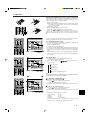
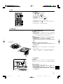
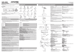
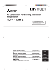
Replacing the Batteries and how to set the current time
4
If no signal is transmitted and the indoor unit’s lamp does not light up even
if the remote controller is operated, the batteries may have run out, so
replace them with new ones as described below.
1 Remove the front lid.
2 Replace the batteries with alkali batteries (size AAA). Make sure that
the batteries are installed in the correct direction. (Insert the minus
pole of the batteries first.)
3 Reattach the front lid.
4 Press the RESET
button
using a thin stick.
min
h
5 Press the
and
button to set the current time.
6 Press the CLOCK button using a thin stick and close the front lid.
If you are not going to use the unit for a long period of time, remove the
batteries to prevent damage which may occur due to leakage of electrolyte.
1
2
3
MODE
FAN
AUTO STOP
VANE
AUTO START
CHECK LOUVER
TEST RUN
SET
6
h
5
min
RESET
CLOCK
Check if your remote controller is the wired type or the wireless type before
referring to the illustration and text for operation procedures.
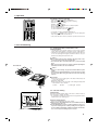
2.1. Switching the unit on/off
˚C
˚C
TEMP.
ON/OFF
A
1
FILTER
1
CHECK TEST
TIMER SET
• The power supply should not be turned off while the air conditioner is in
use. This can cause the unit to break down.
1 Press the ON/OFF button.
AThe ON indicator should light up.
• Even if you press the ON/OFF button immediately after shutting down
the operation in progress, the air conditioner will not start for about three
minutes. This is to prevent the internal components from being damaged.
• If the operation stops due to a power failure, the unit will not automatically restart until the power has been restored. Press the ON/OFF button to restart.
2.2. Mode select
B
B
˚C
˚C
TEMP.
ON/OFF
A
1
1 If the unit is off, press the ON/OFF button to turn it on.
AThe ON indicator should light up.
2 Press the operation mode (
) button and select the operation mode.
B
s
Cooling mode
FILTER
1
2
CHECK TEST
TIMER SET
Fan mode
Heating mode
Drying mode
2
Automatic (cooling/heating) mode
Note:
The heating display and the automatic display does not appear in models that
operate exclusively as cooling only air-conditioner.
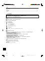
2.3. Selecting a temperature
A
A
˚C
˚C
TEMP.
ON/OFF
1
FILTER
1
CHECK TEST
TIMER SET
TEMP.
s To decrease the room temperature:
1 Press
button to set the desired temperature.
AThe selected temperature is displayed.
• Each time you press the button, the temperature value decreases by 1
°C.
s To increase the room temperature:
1 Press
button to set the desired temperature.
AThe selected temperature is displayed.
• Each time you press the button, the temperature value increases by 1
°C.
• Available temperature ranges are as follows:
Cooling & Drying:
19 - 30 °C
Heating:
17 - 28 °C
Automatic:
19 - 28 °C
Circulation:
— (Not available)
• The display flashes either 8 °C - 39 °C to inform you if the room temperature is lower or higher than the displayed temperature.
3
2. Operation
A
2.4. Selecting a fan speed
1 Press
button to select a desired fan speed.
• Each time you press the button, available options change with the display A on the remote controller, as shown below.
˚C
Fan speed
TEMP.
ON/OFF
High
▼
4-stage
▼
FILTER
Remote controller display
Middle 2
Middle 1
Low
▼
˚C
▼
A
CHECK TEST
The display and the fan speed of the unit will differ in the following situations:
• When STAND BY and DEFROST are displayed.
• Just after the heating mode (while waiting to change to another mode).
• When the temperature of the room is higher than the temperature setting of the unit operating in the heating mode.
• In the dry operation, the indoor fan automatically turns to low-speed
operation. Switching of fan speed is impossible.
TIMER SET
1
1
A
B
C
D
E
F
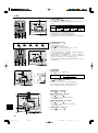
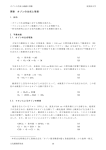
2.5. Adjusting vertical airflow direction
■ Except for PSA/PSH series
The vertical air vane helps select the vertical direction of the airflow.
1 Press
button to select the vertical airflow direction.
• Each time you press the button, the option changes are displayed on
the remote controller, as shown below.
A (swing) → B → C → D → E → A
1Hr.
˚C
˚C
TEMP.
ON/OFF
FILTER
CHECK TEST
1
TIMER SET
• If the room temperature is higher than the temperature set on the remote controller while the unit is defrosting or preparing for heating, the
vertical air vane will move to the horizontal airflow position (B).
• In either cooling or dry mode, if you select C, D or E when the fan
speed is low, middle 2, a display reading “1 Hr” F will appear.
After one hour, the air conditioner will switch automatically to horizontal
air mode B and the display “1 Hr” F will disappear.
• When the heating thermostat is OFF, the louver automatically turns horizontally during defrosting or preparation for heating.
1
2.6. Using the timer
BA
1) Set the current time
ON OFF
˚C
button to display the “CLOCK” B.
Remote
CLOCK
˚C
controller display A
TEMP.
CLOCK →
↑
→
ON
CLOCK
OFF
CLOCK
→ No Display
ON/OFF
ON OFF
FILTER
CHECK TEST
TIMER SET
2
1 Press
1
A BC
2 Each time you press
button, the time increases in increments of
one minute. Each time you press
button, the time decreases in
increments of one minute.
• Press and hold the button to rapidly change the time.
• The time changes in increments of one minute → ten minutes → in units
of hour; in this order.
• Approximately ten seconds after pressing the button, the display on the
remote controller will turn off.
The example shows a timer set for operation start at 8:00 and end at 17:00.
2) Set the mode to continuous as follows
button to display D
1 Press
.
3) Set the time to start the unit as follows
D
2 Press
button to display B .
3 Press
button to set the time that you want the unit to start.
The start time is displayed at A.
ON
TIMER SET
ON
OFF
˚C
CLOCK
˚C
TEMP.
ON/OFF
FILTER
4) Set the time to stop the unit as follows
OFF
2 Press
button to display C .
3 Press
button to set the time that you want the unit to stop.
The stop time is displayed at A.
TIMER SET
CHECK TEST
1
5) Set the mode to timer as follows
TIMER SET
1 Press
3
4
2
button to display D
.
2. Operation
For wireless remote controller
AUTO STOP
AUTO START
1Press the
or
button (TIMER SET).
• Time can be set while the following symbol is blinking.
OFF timer : A
is blinking.
ON timer : A
is blinking.
min
h
and
buttons to set the desired time.
2 Use the
3 Canceling the timer.
AUTO STOP
To cancel the OFF timer, press the
button.
AUTO START
button.
To cancel the ON timer, press the
A
• It is possible to combine both OFF and ON timers.
• Pressing the
ON/OFF button of the remote controller during timer
mode to stop the unit will cancel the timers.
• If the current time has not been set, the timer operation cannot be used.
13
2
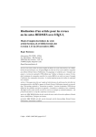
3. Care and cleaning
3.1. Cleaning the filters and the indoor unit
Cleaning the filters
• Clean the filters using a vacuum cleaner. If you do not have a vacuum
cleaner, tap the filters against a solid object to knock off dirt and dust.
• If the filters are especially dirty, wash them in lukewarm water. Take care
to rinse off any detergent thoroughly and allow the filters to dry completely before putting them back into the unit.
Caution:
• Do not dry the filters in direct sunlight or by using a heat source,
such as an electric heater: this may warp them.
• Do not wash the filters in hot water (above 50°C), as this may warp
them.
• Make sure that the air filters are always installed. Operating the
unit without air filters can cause malfunction.
■ PLA-RP·AA
B
A
Caution:
• Before you start cleaning, stop operation and turn OFF the power
supply.
• Indoor units are equipped with filters to remove the dust of suckedin air. Clean the filters using the methods shown in the following
sketches.
C
D
■ PLA-RP·AA
1 Pull the knob on the intake grille in the direction indicated by the
arrow and it should open.
2 Open the intake grille.
3 Release the knob on the center edge of the intake grille and pull the
filter forward to remove the filter.
A Knob
B Grille
C Intake grille D Filter
3.2. Care and cleaning
A
Clean the filter
When the A “FILTER” indicator blinks on the remote controller to alert you
to the necessity of cleaning of the filter.
∗ As a guideline for typical office environment, the long-life filter must be
cleaned every 2,500 operating hours.
˚C
FILTER
˚C
TEMP.
Reset the FILTER indicator
ON/OFF
FILTER
1
CHECK TEST
TIMER SET
1 Press the FILTER button twice after cleaning.
sWhen you press the FILTER button twice, the “FILTER” indicator A
will be turned off and reset.
sThe FILTER indicator provides you with a guideline for the necessity of filter cleaning based on total operating hours in typical indoor air conditions. Depending on different operating environments,
more or less frequent cleaning may be necessary.
5
4. Troubleshooting
Before you call out a repair man, check the following table to see whether there is a simple solution to your problem.
[for wireless remote controller]
Solution
Problem
Turn main power on. Then press the Unit does not start immediately.
POWER ON/OFF button to turn the
unit on.
Wait until power is restored, then
press the POWER ON/OFF button
to turn the unit on.
Problem
Unit does not operate at all.
Solution
Wait until the unit restarts automatically. The compressor may hesitate
resuming because a three-minute
resume prevention circuit is incorporated in the outdoor unit for protection of the compressor.
[for wired remote controller]
Solution
Clean the filter.
Frost forms when the outdoor temperature is low and humidity is high.
Wait for about 10 minutes for the frost
to melt.
The airflow direction suddenly After one hour of cooling-mode operation with the airflow in a downchanges.
ward direction, the unit will automatically change to the “Horizontal airflow” mode.
When the unit is in the heating or defrosting mode, it will automatically
change to the “Horizontal airflow
mode”.
A white mist is expelled from the in- This may occur just after the unit is
turned on when a high level of hudoor unit.
midity is present in the room.
The indicators of the remote control- Turn on the power switch. “ · ” will be
displayed.
ler do not light up when operated.
Problem
Unit does not cool or heat very well.
The unit stops operating before arriving at the set temperature in the
heating mode.
Problem
Solution
CENTRALLY CONTROLLED is dis- The start and stop functions of the
played in the remote controller.
remote controller are not available
when the CENTRALLY CONTROLLED message is lit.
The start and stop functions are not Wait about three minutes (operation
available just after restarting the unit. has stopped to prevent damage to
the air conditioner).
“H0” is displayed in the remote con- An automatic startup test is being
troller.
performed (will last for about two minutes).
An error code is displayed in the re- A self-diagnostic function is being
mote controller.
performed to preserve the air condiThe operating display of the wireless tioner.
remote controller’s receiver is flash- * Do not attempt to make repairs
ing.
yourself. Turn the main switch off
and contact the dealer from whom
you bought the air conditioner. Provide him or her with the name of the
unit and the information displayed
in the remote controller.
NOTE: After a power cut, the unit will not restart automatically. You will have to restart it by pressing the POWER - ON/OFF button on the remote controller.
If none of the above apply, turn the main switch off and contact the dealer from whom you bought the air-conditioner, telling him the model name and the
nature of the problem. Do not try to fix the unit yourself.
In any of the following cases, turn off the main power switch
and contact your local dealer for service:
• The operation lamp (on the main unit) flashes.
• The switches do not work properly.
• The circuit breaker trips frequently (or the fuse blows frequently).
• Water has accidentally been splashed into the unit.
• Water leaks from the unit.
• Something is accidentally dropped into the air-conditioner.
• An unusual noise is heard during operation.
Operating range
Indoor air intake temperature Outdoor air intake temperature
Maximum 35 °C DB, 22.5 °C WB
46 °C DB
Minimum
19 °C DB, 15 °C WB
–5 °C DB
Maximum
28 °C DB
21 °C DB, 15 °C WB
Heating
Minimum
17 °C DB
–11 °C DB, –12 °C WB
Cooling
The following do not indicate any malfunction:
Odours: smells such as tobacco or cosmetic odours may persist after they have been sucked into the unit.
Sound of liquid flowing inside indoor unit: this can occur during or after operation and is simply the sound of refrigerant being circulated inside the unit.
Ticking sound coming from indoor unit: this can occur when cooling or heating has just begun or has just stopped. It is caused by the indoor unit shrinking
or expanding slightly due to the change in temperature.
The message “CENTRALLY CONTROLLED” appearing on the LCD panel: from time to time, this message may come up on the LCD panel. This does not
indicate any malfunction.
Remote Controller Settings for Installing/Replacing Batteries and Restarting Operation (for wireless remote controller)
• Always press the reset button after installing or replacing batteries.
• The initial settings are used when installing or replacing batteries after which the settings for restarting are used.
Operating mode
Temperature setting
Fan speed
Initial Settings
Fan
—
High
Airflow direction
Level
Restarting
Previous operating mode
Previous temperature setting
Previous fan speed setting
Cooling - Dry
Operating mode
Heating
Fan
Level
Previous setting
Level
NOTE: The refrigerant charged in the air conditioner is safe. Refrigerant normally does not leak, however, if refrigerant gas leaks indoors, and comes into contact
with the fire of a fan heater, space heater, stove, etc., harmful substances will be generated.
Be sure to ask the service representative whether there is refrigerant leakage or not when repairs are carried out.
6
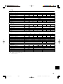
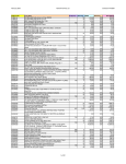
5. Specifications
■ PLA-RP·AA+PU(H)-P·GAA
Model
RP1.6
Capacity (Cooling/Heating) <kW> *1
4.50/4.95
1.72/1.70
Total Input (Cooling/Heating) <kW> *1
Power source (voltage <V>/Frequency <Hz>)
Dimension (Height) <mm> *2
Dimension (Width) <mm> *2
Dimension (Depth) <mm> *2
Fan Airflow rate (Low-Middle2-Middle1-High) <m 3/min> 11-12-13-14
27-28-29-31
Noise level (Low-Middle2-Middle1-High) <dB>
Net weight <kg> *2
RP2
5.60/6.35
2.53/2.20
RP2.5
6.70/7.30
2.57/2.40
RP3
7.70/9.20
3.42/3.48
–
RP4
9.60/10.50
3.68/3.91
RP5
RP6
13.30/15.60 14.20/17.00
5.09/5.54
5.90/6.35
258 (30)
14-15-16-18
28-29-31-33
24 (5)
298 (30)
840 (950)
840 (950)
15-16-18-20 20-23-26-28
28-30-32-34 33-36-39-41
30 (5)
22-25-28-30
37-40-43-45
32 (5)
■ PU(H)-P·GAA
Model
Power source (voltage <V>/Frequency <Hz>)
Dimension (Height) <mm>
Dimension (Width) <mm>
Dimension (Depth) <mm>
Fan Airflow rate <m3/min>
Net weight <kg>
P1.6V
P1.6Y
P2V
P2Y
650
45
54
55
74
■ PLA-RP·AA+PUHZ-RP·VHA
Model
RP1.6
Capacity (Cooling/Heating) <kW> *1
3.60/4.10
Total Input (Cooling/Heating) <kW> *1
1.07/1.12
Power source (voltage <V>/Frequency <Hz>)
Dimension (Height) <mm> *2
Dimension (Width) <mm> *2
Dimension (Depth) <mm> *2
Fan Airflow rate (Low-Middle2-Middle1-High) <m 3/min> 11-12-13-14
Noise level (Low-Middle2-Middle1-High) <dB>
27-28-29-31
Net weight <kg> *2
■ PUHZ-RP·VHA
Model
Power source (voltage <V>/Frequency <Hz>)
Dimension (Height) <mm>
Dimension (Width) <mm>
Dimension (Depth) <mm>
Fan Airflow rate <m3/min>
Net weight <kg>
P2.5V
P3V
P4V
P2.5Y
P3Y
P4Y
V:~/N220-230-240/50, Y:3N~380-400-415/50
855
900
330+20
50
85
79
97
RP2
5.00/6.00
1.55/1.62
RP1.6V
600
800
300+15
35
45
RP2.5
6.00/7.00
1.65/1.85
RP3
7.10/8.00
1.97/2.34
–
RP2V
P6Y
1260
1050
95
112
100
113
RP4
RP5
RP6
10.00/11.20 12.50/14.00 14.00/16.00
3.03/3.39
3.89/4.27
4.99/4.91
258 (30)
14-15-16-18
28-29-31-33
24 (5)
P5Y
298 (30)
840 (950)
840 (950)
15-16-18-20 20-23-26-28
28-30-32-34 33-36-39-41
30 (5)
RP2.5V
RP3V
RP4V
V:~/N 220-230-240/50
943
950
330+30
55
69
22-25-28-30
37-40-43-45
32 (5)
RP5V
RP6V
1350
100
113
*1 Cooling: Indoor 27 °C DB/19 °C WB, Outdoor 35 °C DB
Heating: Indoor 20 °C DB, Outdoor 7 °C DB/6 °C WB
*2 This figure in ( ) indicates panel’s.
7
NK= !"# KKKKKKKKKKKKKKKKKKKKKKKKKKKKKKKKKKKKKKKKKKKKKKKKKKKKKKKKKKKKKKKKKKKKKKKKKKKKKKKKKKKKKKKKKKKKKKKKKKKKKKKKKKKKKKKKKKKKKKKKKKKKKKKKKKKKKKKKKKKKKKKKKKKKKKKKKKKKKKKKKKKKKKKKKKKKKKKKKKKKKKKKKKKKKKKKKKK U
OK= KKKKKKKKKKKKKKKKKKKKKKKKKKKKKKKKKKKKKKKKKKKKKKKKKKKKKKKKKKKKKKKKKKKKKKKKKKKKKKKKKKKKKKKKKKKKKKKKKKKKKKKKKKKKKKKKKKKKKKKKKKKKKKKKKKKKKKKKKKKKKKKKKKKKKKKKKKKKKKKKKKKKKKKKKKKKKKKKKKKKKKKKKKKKKKKKKKKKKKKKKKKKKKKKKKK V
PK= !" KKKKKKKKKKKKKKKKKKKKKKKKKKKKKKKKKKKKKKKKKKKKKKKKKKKKKKKKKKKKKKKKKKKKKKKKKKKKKKKKKKKKKKKKKKKKKKKKKKKKKKKKKKKKKKKKKKKKKKKKKKKKKKKKKKKKKKKKKKKKKKKKKKKKKKKKKKKKKKKKKKKKKKKKKKKKKKKKKKKKKKKKKKKKKKKKKKKKK NN
QK= ! KKKKKKKKKKKKKKKKKKKKKKKKKKKKKKKKKKKKKKKKKKKKKKKKKKKKKKKKKKKKKKKKKKKKKKKKKKKKKKKKKKKKKKKKKKKKKKKKKKKKKKKKKKKKKKKKKKKKKKKKKKKKKKKKKKKKKKKKKKKKKKKKKKKKKKKKKKKKKKKKKKKKKKKKKKKKKKKKKKKKKKKKKKKKKKKKKKKKKKKKK NO
RK= KKKKKKKKKKKKKKKKKKKKKKKKKKKKKKKKKKKKKKKKKKKKKKKKKKKKKKKKKKKKKKKKKKKKKKKKKKKKKKKKKKKKKKKKKKKKKKKKKKKKKKKKKKKKKKKKKKKKKKKKKKKKKKKKKKKKKKKKKKKKKKKKKKKKKKKKKKKKKKKKKKKKKKKKKKKKKKKKKKKKKKKKKKKKKKKKKKKKKKKKKKKKKKKKK NP
NK=
!"#
s !"#$%&'()*+,-./0123456.
s !"#$%&'()*+,-./ -,0. !"#$%&'.
s !"#$%&'()*+,-./012!345.
!"#$
=W
!"#$%&'()*+,-./01234567%89.
=W
!"#$%&'()*+,-./01.
!"#$%&'
W !"#$%&.
W !"#$%&'(.
W !"#$%&'(.
W !"#$%&'()*.
W !"#$%&'()*'.
W !.
W !"#.
ELV W !"#$!%&'()*+,-).+,/0123.
=W
!"#$%&'()*+,-.
=W
!"#$%&'()*+,-./01234567%&. !"#$%&'()*+,-./01234.
!"#$%&'()*+,-."#$%.
!"#$%&'()*+,-./$%0123456/7.
!"#$%&'()*+,-'./012.
!"#$%&'()*+,-./0/12345670"89:;<=>?@ABCDE.
!"#$%&'()*+,-./0123.
!"#$%&'()*+,-./012345,6789:;<=>?.
!"#$%&'()**+,#-+,..
!"#$%&'()*+,#-./01234567. !"#$%&'()*+,-./01.
!"#$%&'()*+,-./012345678.
!"#$%&'()*+,-..
!"#$%&'()*+,-./012345+6781$9:;<=>?@AB.
=W
!"#$%&'(')*+,-./0123.
!"#$%&'"#()*+,-./"#0./.
!"
!"#$%&'()*+,-./.
8
HM04A363_SC.p65
Page 8
2/3/04, 5:20 PM
Adobe PageMaker 6.5C/PPC
OK=
4
1
2
1
2
3
MODE
FAN
AUTO STOP
VANE
AUTO START
CHECK LOUVER
TEST RUN
SET
6
h
5
min
RESET
3
4
5
6
!"#$%&'(
!"#$%&'()*+,-./01234567*+89':;
!"#$%&'()*+,-./01234.
!.
!"#$%^^^ !". !"#$%&'(.E
!"#$%.F
!".
h !"#$%&'()'*.
min
==
= !"#$%.
=
!"#$%&'`il`h !"#$%&'()*.
!"#$%&'()*+,"-./0123-45672389:
!.
CLOCK
!"#$%&'()*+,-./0123'4567!89:;<
!".
OKNK L
˚C
˚C
TEMP.
ON/OFF
A
1
FILTER
1
CHECK TEST
TIMER SET
OKOK B
B
˚C
˚C
TEMP.
ON/OFF
A
!
1 !"#$%&'()lkLlcc L !"#$%&.
A=lk !"#$%&'(.
2 !"#
!"#$%&'().
B
s
!
1
FILTER
1
!
!"#$%&'()*+,-./0%123.
1 lkLlcc.
A=lk !"#$%&'(.
!"#$%&'()*lkLlcc L !"#$%&'
!"#$%&'()*+,-./0$1234567.
!"#"$%&'()*+,-#./01234563'78
lkLlcc L !"#$%&'(.
2
CHECK TEST
!
!
!
TIMER SET
!"L !"
2
W
!"#$%&'()*+,-./012345623.
OKPK A
A
˚C
˚C
TEMP.
ON/OFF
1
FILTER
1
CHECK TEST
TIMER SET
!==
TEMP.
s !"#$
1 =
= !"#$%&.
A= !"#$.
!" #$%&'()*+,-.
s !"#$
1 =
= !"#$%&.
A !"#$.
!" #$%&'()*+,-.
!"#$%&'
!"W
NV=J=PM
W
NT=J=OU
W
NV=J=OU
W
!"#
!UJPV !"#$%&'()'*+,%-.
9
HM04A363_SC.p65
Page 9
2/3/04, 5:21 PM
Adobe PageMaker 6.5C/PPC
OK=
OKQK A
!"#=
1 =
= !"#$%&'().
!"#!$%&'()*+,-.!/0)12A !"#
.
O
˚C
TEMP.
TIMER SET
1
1
C
D
E
F
Q
!"#$%&'()*+,-./0123
pq^ka=_v !"abcolpq !".
!"#$%&'()*+,-./!"01.
!"#$%&'()*+,"-. /01,.
!"#$%&'()*+,-./01234. !"#$
.
OKRK !"#$!=
mp^Lmpe !
!"#$%&'(.
1 = = !"#$%&'$.
!"#!$%&'()*+,-./0%1"2,.
A=EF=→ B → C → D → E → A
1Hr.
˚C
˚C
TEMP.
!"
N
▼
▼
FILTER
B
ON/OFF
CHECK TEST
A
!
▼
˚C
▼
A
ON/OFF
FILTER
CHECK TEST
!"#$%&'()*+,-./01"2345678/9+:
!"#$%&'() *+,EBF.
!"#$%&'()*+,-./+01+=O !"#$C
DE !"#N=eêF . !"#$%&'()*+
!"#$%&B !N=eêF !"#.
!"#$%&'()*+,-./01 23456'7 89
!"#$%.
1
TIMER SET
1
OKSK BA
NF ON OFF
!"
!"#
1 = =
˚C
CLOCK
!"=A
˚C
TEMP.
`il`h=→
↑
ON
CLOCK
=→
OFF
CLOCK
=→
ON/OFF
ON OFF
FILTER
CHECK TEST
TIMER SET
2
!"#`il`hB.
1
2 !"=
= ! "#$%&'()(*!+,= !"#$%&'()*+.
!"#$%&'().
!"#$=→ →= !"#$%&#'.
!"#$%&'()*+,-./01-234.
!"#$%&'($)*UWMM !"#NTWMM.
OF !"#$%&'()*.
PF !"#$%&'()*+,
1 =
A BC
= !"=D= .
2 = = !"=B .
3 =
= !"#$%&'()*+,.
!"#$=A=.
D
ON
TIMER SET
ON
OFF
˚C
CLOCK
QF ˚C
TEMP.
ON/OFF
!"#$%&'()*+,-.
2 = = !"=C= .
3 =
= !"#$%&'()*+,-..
!"#$=A=.
OFF
TIMER SET
FILTER
CHECK TEST
1
RF TIMER SET
!"#$%&'()*+.
1 =
3
= !"=D= =.
2
10
HM04A363_SC.p65
Page 10
2/3/04, 5:22 PM
Adobe PageMaker 6.5C/PPC
OK=
A
AUTO STOP
AUTO START
!"#lcc !"lk !"#$.
!"#$%&'!(= =lkLlcc L !"#$%&'
!"#$.
!"#$%&'()*+,"%-./.
13
2
PK=
!"#$
1 =
==
= !"#$!%.
!"#$%&'()*%+.
lcc !"#$=W=A
.
lk !"#$%=A
.
min
h
==
= !"#$%&.
2 =
3 !".
AUTO STOP
!"lcc !"#$%&=
=.
AUTO START
=.
!"lk !"#$%&=
!"
PKNK !
!"#$%&
!"#$%#". !"#$%&'()*+,-./012
!"#$%.
!"#$%&'()*+,-./0. !"#$%&'(
!"#$%&'()*+,-./0$%&1234.
=
!"#$%&'()*+,-./012345678)*+,9
!"#$%&.
!"#RM !"#$"%&'()*$"%+,.
!"#$%&'(). !"#$%&'()*#+,-./
.
■ PLA-RP·AA
=
!"#$%&'()*+,-./012.
!"#$%&'()*+,-./0. !"#$%&'(
!"#$%.
B
A
C
mi^Jom·^^
1 !"#$%&'()*+,-.$/0'123456-.7
.
2 !"#.
3 !"#$%&'()*+,-./01234567/01.
A=
B=
C= !
D=
D
PKOK A
!
!"
!"#Acfiqbo !"#$%&'()*+,-./01/
.
G !"#$%&'()*+,OIRMM= !"#$%&'"()
.
˚C
FILTER
˚C
TEMP.
cfiqbo
ON/OFF
FILTER
1
CHECK TEST
TIMER SET
1 !"#$%cfiqbo !"#$.
s !"#cfiqbo !"#$%&cfiqbo !"
A !"#$.
scfiqbo !"#$%&'()*+,-./0121345678
!"#$%#&'()*+,-.'/012*34!"56#
!"#"$.
11
HM04A363_SC.p65
Page 11
2/3/04, 5:23 PM
Adobe PageMaker 6.5C/PPC
!
QK=
!"#$%&'()*+,-./0!1'234(56789:;<5=>.
x !"#$z
x
!
!"#$%&'mltbo=lkL lcc !"L !"#$%
.
!"#$%&'(m l t b o
lkLlcc !"L !"#
!.
!"#$%.
!"#$%&'()*+,-./+.
!
!"#$`bkqo^iiv=`lkJ `bkqo^iiv= `lkqoliJ
qoliiba !"#.
iba !"#$%&'()*+
!"#$%&'(.
!"#$%&'()*+,- !P !"#$%&'$
!"#.
!"#$%&.
!"#$#%&'()*+,
!"#$%eM.
O .
!"#$%&'()*.
!"#$%&'()*+,.
!"#$%"#&'()* G !"#$%. !"
.
!"#$%&'()*+.
!"#$%&'()*+,
!"#$%.
!"#$%&'mltboJlkLlcc
!"L
!"#$%&'()*.
!"#$%&'()*+,-*./0123456789:;<(=>?@ABCDEF7GH.
!"#$%&'()*+,'-./0123456789,:;<=W
!"#$%&'(.
!"#$%.
!"#$%&'()''*+.
!"#$%&.
!.
!"#$%&'()*.
!"#$%&'(.
!
!"#$%&'#()*!+
!"#$%&'()*+, !"#$%&'()*+, !.
!"#$%&'()z
!
!".
!"#$%&'().
!"#$%&'()*+,- !"#$%&#'()*+,
. !NM !"#$.
!"#$.
!"#$%&'()*+
!"#$%.
N !"#$%&'()*
!"#$%&.
!"#$%&'()*+, !"#$%&'()*.
!"#$%&'()*+,,
!"#$%&'().
!"#$%&'(&).
!"#$%&'().
!"#$%&'()*.
W
!"#$%.
!"#$%&'.
!
!"#
!"#
PR !"#$%OOKR !"#$
QS !"#$
NV !"#$%NR !"#$
R !"#$
OU !"#$
ON !"#$%NR !"#$
NT !"#$
NN !"#$%&NO !"#$
!"#$%&'()*+,-./0W
!"#$%&'()*+,-./0.123456789:.
!"#$%&'()*+,-./01,-23456789:;<+=$#>+?@&'(.
!"#$%&'()*+,-./0123./456789:. !"#$%&'()$*+,-./$012345678$.
!`bkqo^iiv=`lkqoliiba !"#$%&'()*i`a !"#$%&'()i`a !"#$%&'()*+,.
L
!"#$%&'()*+,-./012./034
!"#$%&'()*+,)-.
!"#$%&'()*+,-./&01#$2345.
!
!
!
!
W
!
!
!"#$
!"#$
!"#$
!
J
!"
!"#$%&'()*+%. !"#$%&'()*+ ,-./0%&'123456,789:6;789<=>?@ABC'D$EFGH
.
!"#$%&'()!"*+,-./012345.
12
HM04A363_SC.p65
Page 12
2/3/04, 5:24 PM
Adobe PageMaker 6.5C/PPC
RK=
■ PLA-RP·AA+PU(H)-P·GAA
!"#$%&Yât[*1
!"#$%&'Yât[*1
!Ys[ Yeò[
!"Yãã[*2
!"Yãã[*2
!"Yãã[*2
!"#$%&JOJNJ YãPLãáå[
!"#JOJNJ YÇ_[
YâÖ[*2
RP1.6
4.50/4.95
1.72/1.70
RP2
5.60/6.35
2.53/2.20
RP2.5
6.70/7.30
2.57/2.40
RP3
7.70/9.20
3.42/3.48
–
RP4
9.60/10.50
3.68/3.91
RP5
RP6
13.30/15.60 14.20/17.00
5.09/5.54
5.90/6.35
258 (30)
11-12-13-14
27-28-29-31
14-15-16-18
28-29-31-33
24 (5)
298 (30)
840 (950)
840 (950)
15-16-18-20 20-23-26-28
28-30-32-34 33-36-39-41
30 (5)
22-25-28-30
37-40-43-45
32 (5)
■ PU(H)-P·GAA
P1.6V
P1.6Y
!Ys[ Yeò[
!"Yãã[
!"Yãã[
!"Yãã[
!"#YãPLãáå[
YâÖ[
■ PLA-RP·AA+PUHZ-RP·VHA
!"#$%&Yât[*1
!"#$%&'Yât[*1
!Ys[ Yeò[
!"Yãã[*2
!"Yãã[*2
!"Yãã[*2
!"#$%&JOJNJ YãPLãáå[
!"#JOJNJ YÇ_[
YâÖ[*2
■ PUHZ-RP·VHA
!Ys[ Yeò[
!"Yãã[
!"Yãã[
!"Yãã[
!"#YãPLãáå[
YâÖ[
P2V
P2Y
P2.5V
P3V
P4V
P2.5Y
P3Y
P4Y
V:~/N220-230-240/50, Y:3N~380-400-415/50
855
900
330+20
50
85
79
97
650
45
54
55
74
RP1.6
3.60/4.10
1.07/1.12
RP2
5.00/6.00
1.55/1.62
RP2.5
6.00/7.00
1.65/1.85
RP3
7.10/8.00
1.97/2.34
–
RP1.6V
600
800
300+15
35
45
14-15-16-18
28-29-31-33
24 (5)
RP2V
P6Y
1260
1050
95
112
100
113
RP4
RP5
RP6
10.00/11.20 12.50/14.00 14.00/16.00
3.03/3.39
3.89/4.27
4.99/4.91
258 (30)
11-12-13-14
27-28-29-31
P5Y
298 (30)
840 (950)
840 (950)
15-16-18-20 20-23-26-28
28-30-32-34 33-36-39-41
30 (5)
RP2.5V
RP3V
RP4V
V:~/N 220-230-240/50
943
950
330+30
55
69
22-25-28-30
37-40-43-45
32 (5)
RP5V
RP6V
1350
100
113
*1 !"OTa_LNVt_ PRa_
!"OMa_ Ta_LSt_
*2 !"#$%&'().
13
HM04A363_SC.p65
Page 13
2/3/04, 5:25 PM
Adobe PageMaker 6.5C/PPC
Please be sure to put the contact address/telephone number on
this manual before handing it to the customer.
HEAD OFFICE: MITSUBISHI DENKI BLDG., 2-2-3, MARUNOUCHI, CHIYODA-KU, TOKYO 100-8310, JAPAN
BG79U016H03
Printed in Japan