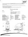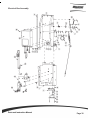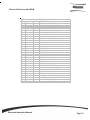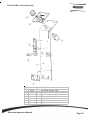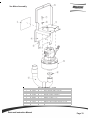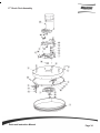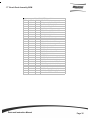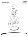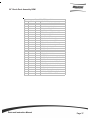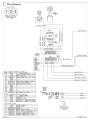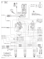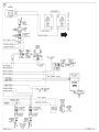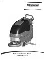
1
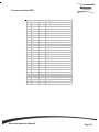
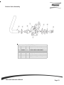
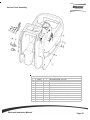
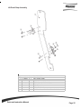
Parts and Instruction Manual
E17/E20 Scrubber
This manual is furnished with each new MINUTEMAN E17/E20. This provides the necessary operating and
preventive maintenance instructions. Operators must read and understand this manual before operating or
servicing this machine.
This machine was designed to give you excellent performance and efficiency. For best results and minimal cost,
please follow the general guidelines below:
• Operate the machine with reasonable care.
• Follow the manufacturers suggested maintenance instructions as provided in this booklet.
• Use original Minuteman supplied parts.
TECHNICAL SPECIFICATIONS
Model
E17/E20
Model No.
E17BD / E17BDCE / E17BDQP / E17BDQPCE
E17BDQPG / E17BDQPGCE
E20BD / E20BDCE / E20BDQP / E20BDQPCE
E20BDQPG / E20BDQPG
Current (Max)
Voltage, Batteries
Battery Capacity (Lead Acid)
Battery Capacity (Gel)
Sound Level
Gross Weight (with Batteries)
Gross Weight (w/o Batteries)
Squeegee Width
Working Grade Transport
Working Grade Cleaning
Parts and Instruction Manual
32 amps
24V
105AH @ 20Hr
100AH @ 20Hr
69 dBA
310 lbs (141 kg)
200 lbs (91 kg)
33” (84cm)
2%
2%
Working Width E17
Working Width E20
Working Speed
Vacuum Flow
Vacuum Waterlift
Vacuum Power
Brush Speed
Solution Tank Capacity
Recovery Tank Capacity
17” (43cm)
20” (60cm) E20
2.5 mph (4 km/hr)
65 cfm (110 m³/hr)
45 in.H2O (112 mbar)
3/4hp (560W)
180 RPM
12 gal (45 ltr)
13 gal (50 ltr)
Table of Contents
Important Safety Instructions ............................................................................................................ 1
During Operation ............................................................................................................................. 1
When Servicing or Maintaining Machine ......................................................................................... 1
Inspection & Unpacking ..................................................................................................................... 2
Electrical .............................................................................................................................................. 2
Batteries .............................................................................................................................................. 2
Operator Responsibility ..................................................................................................................... 2
Machine Overview .............................................................................................................................. 3
Front ................................................................................................................................................ 3
Rear ................................................................................................................................................ 3
Control Panel .................................................................................................................................. 4
The Control Panel ............................................................................................................................... 4
Bail Handle ...................................................................................................................................... 4
Handle Adjustment Knobs ............................................................................................................... 4
Key Switch ...................................................................................................................................... 4
Squeegee Lift Lever ........................................................................................................................ 4
Solution Control Lever ..................................................................................................................... 4
Battery Gauge ................................................................................................................................. 4
Charge Status Indicator ................................................................................................................... 4
Optional Hour Meter ........................................................................................................................... 5
Optional Solution Solenoid ................................................................................................................ 5
Circuit Breakers .................................................................................................................................. 6
Battery Compartment ......................................................................................................................... 6
Rear Squeegee .................................................................................................................................... 7
Handle Adjustment ............................................................................................................................. 8
Horizontal Adjustment ..................................................................................................................... 8
Angle Adjustment ............................................................................................................................ 8
Solution Tank Drain Hose / Level Indicator ...................................................................................... 9
Solution Tank Drain Hose ................................................................................................................ 9
Solution Level Indicator ................................................................................................................... 9
Solution Fill Filter ............................................................................................................................... 9
Brush Load / Unload ........................................................................................................................ 10
Loading Brush ............................................................................................................................... 10
Unloading Brush ............................................................................................................................ 10
Screened Float .................................................................................................................................. 11
Screened Float Removal .................................................................................................................. 11
The E17/E20 ...................................................................................................................................... 12
Machine Operation ........................................................................................................................... 13
Parts and Instruction Manual
Optional Equipment Operation ........................................................................................................ 13
Hour Meter ................................................................................................................................... 13
Solution Solenoid .......................................................................................................................... 13
After Use ............................................................................................................................................ 14
Maintenance ...................................................................................................................................... 14
General Machine Troubleshooting .................................................................................................. 15
Exploded Views ................................................................................................................................ 16
Main Assembly .............................................................................................................................. 16
Main Assembly BOM ..................................................................................................................... 17
Brush Drive Base Assembly .......................................................................................................... 18
Brush Drive Base Assembly BOM ................................................................................................. 19
E17/20 Base Assembly ................................................................................................................. 20
Chassis Assembly ......................................................................................................................... 21
Chassis Assembly BOM ................................................................................................................ 22
Solution Valve Assembly ............................................................................................................... 23
Solution Tank Assembly ................................................................................................................ 24
Lift Pedal Stop Assembly ............................................................................................................... 25
Recovery Tank Assembly .............................................................................................................. 26
Recovery Tank Assembly BOM ..................................................................................................... 27
Handle Assembly .......................................................................................................................... 28
Battery Tray Assembly .................................................................................................................. 29
Electrical Box Assembly ................................................................................................................ 30
Electrical Box Assembly BOM ....................................................................................................... 31
Electrical Box Cover Assembly ...................................................................................................... 32
Vac Motor Assembly ...................................................................................................................... 33
17” Brush Deck Assembly ............................................................................................................. 34
17” Brush Deck Assembly BOM .................................................................................................... 35
20” Brush Deck Assembly ............................................................................................................. 36
20” Brush Deck Assembly BOM .................................................................................................... 37
E17 Brush Hub Assembly .............................................................................................................. 38
E20 Brush Hub Assembly .............................................................................................................. 39
Rear Squeegee Assembly ............................................................................................................. 40
Squeegee Mechanism Assembly .................................................................................................. 41
Wiring Diagrams ............................................................................................................................ 42
Minuteman International Made Simple Commercial Limited Warranty ........................................ 45
Parts and Instruction Manual
Important Safety Instructions
Operators must read and understand this manual before operating or maintaining this
machine.
Do not operate this machine in flammable or explosive areas.
This machine is designed solely for scrubbing dirt and dust in an indoor environment. Minuteman
does not recommend using this machine in any other capacity.
The following information below may cause a potential hazard to the operator and equipment.
Read this manual carefully and be aware when these conditions can exist. Take necessary
steps to locate all safety devices on the machine and train the personnel operating the machine.
Report any machine damage or faulty operation immediately.
Do not use machine if it is not in proper operating condition.
For Safety During Operation
Keep hands and feet clear of moving parts while machine is in operation.
Make sure all safety devices are in place and operate properly. All covers, doors and latches
must be closed and fastened before use.
During operation, attention should be paid to other persons in the work area and especially if
small children are present.
Electric motors and components can cause an explosion when operated near explosive materials
or vapor. Do not operate this machine near flammable materials such as solvents, thinners,
fuels, grain dust, etc.
Store or park this machine on a level surface only. To prevent unauthorized use, machine should
be stored or parked with the key removed.
This machine is designed for level operation only. Do not operate on ramps or inclines greater
than 2%.
This machine is not suitable for picking up hazardous dusts.
Use caution when moving this machine into areas that are below freezing temperatures. Any
water in the tanks or hoses can cause damage to the machine.
For Safety When Servicing or Maintaining Machine
Stop on level surface.
Disconnect the power to the machine by pulling the red Battery Connector located under the
recovery tank near the batteries.
Avoid moving parts. Do not wear loose jackets, shirts, or sleeves when working on machine.
Avoid contact with battery acid. Battery acid can cause burns. When working on or around
batteries, wear protective clothing and safety glasses. Remove metal jewelry. Do not lay tools or
metal objects on top of batteries.
Do not clean machine with a pressure washer.
Authorized personnel must perform repairs and maintenance. Use Minuteman supplied
replacement parts.
SAVE THESE INSTRUCTIONS
Parts and Instruction Manual
Page 1
Inspection & Unpacking
Carefully unpack and inspect your E17/E20 Walk-Behind Scrubber for shipping damage. Follow
unpacking instructions on shipping pallet. Each unit has been tested and thoroughly inspected before
shipment. Any damage is the responsibility of the delivery carrier who should be notified immediately.
Electrical
This machine is battery operated and designed to operate on 24 volts DC (2) 12-volt batteries.
Batteries
The recommended batteries are rated 105Ah (Minuteman P/N 956712) or 100Ah (Minuteman P/N
956100). We do not recommend mixing AMP hour capacities. Alternate battery sets can be used if
they equal physical size and capacity.
Operator Responsibility
Read this manual carefully before operating this machine.
The operator is responsible in taking care of the daily maintenance and check ups of the machine to
keep it in good working condition. The operator must inform the service mechanic or supervisor when
the scheduled maintenance intervals are required as stated in the MAINTENANCE section of this
manual.
Before starting familiarize yourself with the machine and its controls (see “Machine Overview, Front”,
“Machine Overview, Rear”,“Control Console” diagrams).
Parts and Instruction Manual
Page 2
Machine Overview - Front
A
B
A
B
C
D
E
F
G
H
C
CUP HOLDER
SOLUTION FILL PORT
RECOVERY TANK LID
RECOVERY TANK
BRUSH DECK
FRONT WHEEL
REAR CASTER
SOLUTION TANK
D
H
E
K
G
F
Machine Overview - Rear
A
H
B
C
I
D
E
J
F
K
G
A
B
C
D
E
F
BAIL HANDLE
SQUEEGEE LIFT LEVER
SOLUTION CONTROL LEVER
RECOVERY TANK DRAIN HOSE
ONBOARD CHARGER CORD
CIRCUIT BREAKERS
Parts and Instruction Manual
G
H
I
J
K
RECOVERY HOSE
CONTROL PANEL
SOLUTION TANK DRAIN HOSE / LEVEL INDICATOR
BRUSH LIFT PEDAL
REAR SQUEEGEE
Page 3
Machine Overview - Control Panel
A
B
C
D
E
F
G
BAIL HANDLE
HANDLE ADJUSTMENT KNOB
KEY SWITCH
SQUEEGEE LIFT LEVER
SOLUTION CONTROL LEVER
BATTERY GAUGE
CHARGE STATUS INDICATOR
A
D
C
B
F
E
G
The Control Panel
For operator ergonomics, the control panel houses all the primary functions. Controls are grouped in a central area
at the rear of the machine.
Bail Handle
(A) When the scrubdeck is lowered to the floor, The Bail Handle Enables the brush motor and moves the machine
forward once depressed. This also allows the operator to automatically load the brush when the scrubdeck is
lowered.
Handle Adjustment Knobs
(B) Allows the handle position to be raised or lowered.
Key Switch
(C) Controls the machine’s power (Brush Unload/Off/On) with a key for safety. This switch, when turned counter
clock-wise, operates the auto brush unload when scrubdeck is in the raised position. When it is turned to the on
position, the machine will operate.
Squeegee Lift Lever
(D) When actuated to the top position, the squeegee is lowered and the vacuum motor is turned on. When locked
in the bottom position, the squeegee is raised and the vacumm motor shuts off.
Solution Control Lever
(E) This lever controls the rate at which solution is put down. Moving the lever up will increase the amount of
solution. Moving the lever down will decrease the solution rate. Moving the lever all the way down shuts off solution
flow.
Battery Gauge
(F) This gauge displays the remaining battery charge.
Charge Status Indicator
(G) This gauge displays the status of the batteries during charging. The gauge has a readout of 3 LEDs. 1 Green,
1 yellow, 1 Red. Green indicating a full charge, Red indicating the batteries are charging.
Parts and Instruction Manual
Page 4
Optional Hour Meter
Minuteman offers an optional hour meter for the E17/E20. The optional kit replaces the
power cord mounting bracket at the rear of the machine with one that contains an hour
meter.
Kit# K-E1720HM
Optional Solution Solenoid
Minuteman offers an optional solution solenoid for the E17/E20. The optional solenoid
automatically turns off the solution flow when the brush motor is not active.
Kit# K-E1720S
Parts and Instruction Manual
Page 5
Circuit Breakers
The circuit breaker is located at the bottom of
the back panel of the machine.The 4-amp
breaker (A) protects the main controls circuit,
The 30-amp breaker (B) protects the brush
motor circuit, and the 20-amp breaker (C)
protects the vacuum motor circuit.
A
B
C
MAIN CONTROL BREAKER
BRUSH MOTOR BREAKER
VACUUM MOTOR BREAKER
If any of the functions above are not
operating, check if the circuit breaker buttons
have tripped. Press to reset.
A
B
C
Battery Compartment
The battery compartment is located under the recovery tank. The Battery compartment can be accessed for servicing and maintenance by tilting the
recovery tank (make sure recovery tank has been
drained before tilting). The battery compartment
contains two 12-volt batteries connected in series.
Connect the batteries according to the battery connection diagram (see diagram). The recommended
batteries are 105Ah (Minuteman P/N 956712) or
100Ah (minuteman P/N 956100) Gel. The battery
tray may be drained if neccessary using the orange drain hose located above the rear caster on
the right side of the machine.
Parts and Instruction Manual
Page 6
Rear Squeegee
The rear squeegee is the main element of the conduit that transfers the spent solution
into the recovery tank. A daily maintenance check of this component is essential to have
optimum machine performance. The blade configuration has two usable edges and can
be turned inside out to utilize the opposite side of the blade. If streaking occurs it is time
to turn the blade to good edge or replace if this has already been done. The blade can be
accessed by removing the 6 adjusting nuts (A), 2 bumper wheels (B), and the squeegee
mounting bracket (E).
B
A
E
D
C
A
B
C
D
E
Parts and Instruction Manual
Adjusting Nut (6)
Squeegee Bumper Wheel (2)
Squeegee Casting Assembly
Squeegee Blade
Squeegee Mounting Bracket
Page 7
Handle Adjustment
The E17/E20 handle was designed with operator comfort in mind. The angle and horizontal
position of the handle can be adjusted to suit the needs of the operator.
Angle Adjustment
The handle angle can be adjusted without tools by
loosening the angle adjustment knob (A) on each
side and rotating the handle to the desired position.
There are 5 angular positions 11.25° apart for a
total of 45° between the minimum and maximum
position.
A
Horizontal Adjustment
The horizontal position can be adjusted by
removing the 4 mounting bolts (B) (2 each side)
with a 9/16” socket and sliding the mounting plate
(P) to one of the 3 available positions. The machine
is shipped from the factory in position 1.
3
P
Plate Position 3
(Fully Extended)
Parts and Instruction Manual
Plate Position 2
2
1
B
Plate Position 1
(Shipping Position)
Page 8
Solution Tank Drain Hose / Level Indicator
Solution Tank Drain Hose
The solution tank may be drained by removing
the Solution Tank Drain Hose (A) from the
Hose Barb (B) and routing the hose to a floor
drain.
B
A
Solution Level Indicator
The Solution Tank Drain Hose also serves as a
water level indicator for the solution tank. The
amount of water remaining in the solution tank
can be seen through the clear drain hose. Level
markers molded into the solution tank are
positioned at 1/4, 1/2, 3/4, and full levels.
Solution Fill Filter
A
The Solution Fill Filter (B) should be
cleaned regularly. To remove, simply open
the Solution Tank Lid (A) and pull the filter
out.
Parts and Instruction Manual
B
Page 9
Brush Load / Unload
Loading Brush
To load the brush, first center
the E17/E20 brush deck over
the scrub brush.
Lower the scrub deck by
releasing the deck lift pedal.
With the key turned on, pull the
bail handle to spin the scrub
brush onto the scrubdeck.
Momentarily (1 to 2 seconds)
turn the key to the “Brush
Unload” position.
If done correctly the brush
should release from the scrub
deck and fall to the floor.
Unloading Brush
To unload the brush, first lift the
scrub deck by pressing down
on the deck lift pedal . Make
sure the pedal is in the “home”
position shown below.
Parts and Instruction Manual
Note: The brush will release
only when the key returns to the
off position (O).
Page 10
Screened Float
If the recovery tank (C) is overfilled or a large amount
of foaming is present, the screened float (B) blocks
the vacuum intake inside the tank protecting the
vacuum motor and internal electronics from water
damage. It is essential to keep the float in working
order through regular maintenance.
A
B
C
The float should be cleaned daily by thoroughly
rinsing with a hose. Removal of the screened float
is not necessary for daily maintenace.
At least once a month the screened float should be
completely removed, cleaned, and checked for any
damage to the seal or metal screen.
WARNING: Damage to the machine may occur
if operated without the screened float properly
in place.
Screened Float Removal
The screened float is positioned between the vacuum
manifold (A) and recovery tank (C). The screened
float (B) can be accessed by removing the 1.5” bolt
(D) and two 1.25” bolts (E) that attach the manifold
to the recovery tank using a 7/16” socket.
D
E
E
F
G
A
A
B
C
D
E
F
G
Vacuum Manifold
Screened Float
Recovery Tank
1.5” Bolt
1.25” Bolt (2)
Helical Washer (3)
Flat Washer (3)
Parts and Instruction Manual
B
Page 11
The E17/E20
This machine was designed with total operator comfort and ease of use in mind. All machine
components have been designed as a total system to efficiently clean dirty floors. The E17/E20 has
two available scrub head types and sizes to fit specific applications. Please contact your Minuteman
representative for specific recommendations for the correct scrub head type, size, and brush type
and chemical applications.
Before using the machine, always perform the following steps to ensure proper machine operation:
-Check under the machine for leaks.
-Check the rear squeegee for wear and damage.
-Check the solution and recovery tank levels.
After using the machine, always perform the following steps:
-Check the battery charge level. Charge batteries if necessary.
When charging batteries, extra precaution is required:
Battery acid can cause burns. When working on or around batteries, always wear protective
clothing and safety glasses. Remove metal jewelry. Do not lay tools or metal objects on top of the
batteries.
Charging batteries generate explosive gasses. DO NOT CHARGE BATTERIES WHEN OPEN
FLAMES OR SPARKS ARE PRESENT. DO NOT SMOKE. Charge the batteries in a well-ventilated
area. Fluid levels should be checked before and after charging and maintained at the proper levels.
If low, add distilled water until the metal plates are covered. If the machine is not used for an
extended period of time, batteries should be kept fully charged with a boost charge once a week.
-Check for wire, string, or twine wrapped around the scrub brushes.
-Check the rear squeegee for wear and damage.
-Check the rear squeegee suction hose for obstructions.
-Drain and clean the recovery tank.
-Check under the machine for leaks.
-Check the service records to determine maintenance requirements.
WARNING!
Be sure you understand the machine controls and their functions.
While on ramps or inclines, avoid sudden stops when tanks are filled.
Avoid abrupt sharp turns. Slow down driving speed when going downhill.
Parts and Instruction Manual
Page 12
Machine Operation
To Turn on Machine:
Turn key to operate position ( I )
To Turn on Vacuum:
Lower squeegee into operate position, vacuum motor will turn on automatically.
To Turn on Brush Motor:
Move brush lift pedal from the “home” (down) position to the operating position (up). Depress
the operator bail handle. Brush motor will turn on and assist to propel the machine forward.
To Turn on Cleaning Solution:
Move solution lever from closed (down) position up to the desired flow position.
NOTE: When you no longer want solution or stop the machine for an extended period
of time, you must move the solution lever back to the closed (down) position. Otherwise,
solution will continue to flow onto the floor.
To Unload Brush/Pad Driver
Raise the brush deck with the deck lift pedal, foot pedal must be in its “home” position for the
brush to unload. Turn operator keyswitch to the Brush Unload position for approximatedly 1-2
seconds, then release keywitch back to off position (O). Brush will release and fall to the floor.
CAUTION: Make sure brush deck is clear of all personnel and obstructions before operating
Brush Unload.
To Charge Batteries:
When the battery status indicator reaches the red zone the batteries need to be recharged.
Take the machine to a well ventilated area, unwind the battery charger power cord from the
electrical box cover and plug into an appropriate power source. After approximately 10 seconds
the battery charge status indicator will turn on. Be sure to check the battery water levels as
recommended.
WARNING: Charging batteries generates explosive gasses. Do not charge batteries when open
flames or sparks are present. Do not smoke. Charge the batteries in a well-ventilated area.
Optional Equipment Operation:
Hour Meter:
Hour meter will automatically record operating time of the brush motor.
Solution Solenoid:
Water solenoid will operate when the brush motor is turned on. The solution lever must be
moved to the desired operating position, but does not need to be moved to the closed
position when stopping for brief periods.
Parts and Instruction Manual
Page 13
After Use
When finished scrubbing, lift the scrub deck and turn the solution lever off, water flow will cease. Lift the rear
squeegee (the vacuum motor will turn off). Move the machine to a service area for daily maintenance and
review items that may need service.
Empty the solution tank, by disconnecting the solution tank drain hose from the barb fitting over a drain.
Rinse the tank with clean water to prevent any build-up of dried chemicals that could clog the plumbing.
Empty and clean the recovery tank by flushing with a hose. Be sure to also clean the float shut off screen.
Remove the brushes or pad holders and rinse them in warm water and hang to dry.
Remove the rear squeegee, rinse with warm water and reinstall after cleaning.
Check the maintenance schedule in the next section and perform any required maintenance before storing
the machine.
Store the machine indoors in a clean dry place. Keep from freezing. Leave solution and recovery tank lids
open for ventilation to prevent odor build-up.
Turn Key switch OFF (O) and remove key.
Maintenance
Daily
Charge Batteries
Weekly
Check Each
Battery Cell(s)
Water Level
Check/Clean Tanks Inspect Scrub
& Hoses
Housing Skirts
Check/Clean/Rotate Inspect and
the Brushes/Pads
Clean Solution
Filter
Check/Clean the
Squeegee
Check/Clean
Vacuum Shut-Off
Float in Recovery
Tank
Monthly
Lubrication –
Grease Fittings
Yearly
Check Carbon
Brushes
Have a qualified service technician check the vacuum motor carbon motor brushes once a year or after 300 operating hours.
The brush motor carbon brushes should be checked every 500 hours or once a year.
NOTE: Refer to the Service Manual for more detail on maintenance and service repairs.
Regularly scheduled lubrication of certain machine parts should be performed to insure trouble-free
operation of the machine. Apply a generous amount of grease into the fittings on the machine until grease
seeps out around the bearings.
The grease points are listed below:
Rear squeegee caster wheel axle (2)
Rear squeegee caster swivel (2)
Apply lubricant or light machine oil to lubricate the:
Rear squeegee general pivot points
Scrub deck linkages
Parts and Instruction Manual
Page 14
General Machine Troubleshooting
Problem
Poor water pick-up
Poor scrubbing performance
Inadequate solution flow or
no solution to the floor
Machine does not operate
Possible Cause
Worn or torn squeegee blades
Recovery tank full
Recovery tank drain hose leak
Recovery tank lid gasket leak
Debris caught in squeegee
Vacuum hose clogged
Using too much solution
Recovery hose to squeegee or recovery
tank disconnected or damaged
Worn brushes
Wrong brush or cleaning chemical
Debris caught on scrub brushes
Moving machine too fast
Not using enough solution
Low battery charge
Solution tank empty
Solution lines, valves, filter or spray jets
clogged
Solution Lever in down position
Tripped Control Power circuit breaker
Remedy
Rotate or replace blades
Empty recovery tank
Secure drain hose cap or replace
Replace gasket lid cover properly
Clean squeegee
Remove debris and flush hose
Adjust solution control valves
Reconnect or replace recovery hose
Batteries have low charge
Recharge batteries
Battery charger operating
Unplug battery charger when charge
is complete
Empty recovery tank
Empty recovery tank.
Recovery tank full
Excessive foaming in recovery tank.
Rotate or replace brushes
Consult Minuteman
Remove debris
Slow down
Adjust solution flow setting
Recharge batteries
Fill solution tank
Flush lines, and clean solution filter
and spray jets
Move lever up
Reset breaker
Use less or change chemical.
Vacuum motor does not turn
on
Brushes do not unload
Carbon Brushes worn
Vacuum switch disconnected
Tripped vacuum motor circuit breaker
Broken vacuum limit switch
Squeegee in raised position
Foot pedal not in “home” position
Tripped brush motor circuit breaker
Broken brush motor switch
Damaged brush block or drive hub
Parts and Instruction Manual
Use defoaming agent.
Replace carbon brushes
Connect wiring
Reset breaker
Replace switch
Lower squeegee
Place pedal in notch
Reset breaker
Replace switch
Replace
Page 15
Exploded Views
Main Assembly
Parts and Instruction Manual
Page 16
Main Assembly BOM
BILL OF MATERIAL
ITEM PART NO. REQ'D DESCRIPTION
1
172010
1
HOSE, CLEAR VAC W/ 45 CUFF
2
172018
1
SOLUTION TANK LID ASSY
3
172090
1
BRUSH DECK ASSY 17"
3A
172100
1
BRUSH DECK ASSY 20"
4
172117-2
1
17" PAD DRIVER
4A
172120-2
1
20" PAD DRIVER
5
172159
1
FILTER, FILL PORT, ES1720
6
172170
1
BD SQUEEGEE LIFT MECH ASSY
7
210080
1
SQUEEGE ASY COMP 20" STR
8
711118
1
SCR-ST-A 10 X .75 SS
9
711374
3
NUT-NYLOC 5/16-18
10
711523
3
WSR-WAVE .37X .68 X .08
11
711569
1
WSR-FLT .390 X .880 X .062 NYL
12
711575
3
WSR-FLT .31x.75x..06ST
13
712081
3
SHOULDER BLT 5/16-18 X 3/8 X .75
14
712143
1
BLT-SHLD 3/8 X 2.0, 5/16-18
15
712301
3
WSR-FLAT .37 X .87 X .06
16
712908
2
NUT-FLANGED WIZZ 10-24
17
715917
2
DECAL, E17
17A
715920
2
DECAL, E20
18
740164-1
1
JUMPER CABLE ASSY, RED 4G 12"
19
747649
1
CABLE ASSY, BATTERY E17
20
956712
2
BATTERY, 12V 105 AH
20G
956100
2
GEL BATTERY 12V 100AH
21 172001BD-120
1
BRUSH DRV BASE ASSY-120V CHARGER
21CE 172001BD-230
1
BRUSH DRV BASE ASSY-230V CHARGER
22
715914W
1
DECAL, MINUTEMAN W/SWOOSHES, WHITE
23
172008
1
SOLUTION TANK LID
24
712145
1
SCR-MC 6-32 X .37 PPH SS
25
172123
1
CHAIN, BEADED SS W/ EYELETS
ITEM
4.1
4.2
4.3
4A.1
4A.2
4A.3
PART NO.
172117-1
172117-3
172117-4
172120-1
172120-3
172120-4
Parts and Instruction Manual
OPTIONAL BRUSHES
DESCRIPTION
BRUSH, 17" NYLON
BRUSH, 17" NYLO GRIT
BRUSH, 17" STRATA GRIT
BRUSH, 20" NYLON
BRUSH, 20" POLY GRIT
BRUSH, 20" STRATA GRIT
Page 17
Brush Drive Base Assembly
Parts and Instruction Manual
Page 18
Brush Drive Base Assembly BOM
BILL OF MATERIAL - 172001BD-120/230
ITEM PART NO.
REQ'D DESCRIPTION
1
172002
1
BD CHASSIS ASSY, ES1720
2
172012
1
BATTERY TRAY ASSY
3
172016
1
E1720 BD HANDLE ASSY
4
172032
1
LIFT PEDAL WMT
5
172050
1
VAC MOTOR ASSY
6
172055
1
BKT, VAC AREA INSIDE COVER
7
172070-120
1
ELEC BOX BD ASSY 120V
7A
172070-230
1
ELEC BOX BD ASSY 230V
8
172073
1
BD ELEC BOX COVER ASSY
9
172085
2
KNOB, 3/8-16 STUD, 3 LOBE
10
172112
1
SOL CONTROL ASSY
11
172129
1
BKT, PWR CORD MOUNT
12
172157
1
LIFT PEDAL STOP ASSY
13
172179
1
CHARGER INLET ASSEMBLY
14
172184
1
FOAM COVER, REAR 1
15
172185
1
FOAM COVER, REAR 2
16
172187
1
FOAM COVER, FRONT 2
17
210142
1
PEDAL PAD
18
293080
1
STRAIN RELIEF-HEYCO 1207
19
342440
1
FITTING, TEE 3/4MPT 1/2BARB PP
20
430156
1
HOSE, 1/2 X 42 CLEAR
21
450093
2
CRIMP CLAMP 3/4" STEPLESS
22
710178
10
SCR-MC 1/4-20 X .50 TRUSS STPL
23
710380
5
SCR-MC RD HD 1/4-20 X .75 STL PL
24
710985
2
SCR-SC 3/8-16 X .62 ST PL
25
711379
2
NUT, FLANGED WIZZ 5/16-18
26
711504
2
WSR-FLAT 1/4 ID SS
27
711507
2
WSR-FLAT .37 X 1.12 X .06
28
711508
2
WSR-FLAT .44X 1.0X.08
29
711519
3
WSR- FLAT .25 X 1.01 X .06
30
711523
1
WSR-WAVE .37X .68 X .08
31
711543
1
WSR-HELICAL #10
32
711544
9
WSR-HELICAL 1/4
33
711546
6
WSR-HELICAL 3/8
34
711575
6
WSR-FLT .31x.75x..06ST
35
712041
1
BLT- SHLDR 1/4-20 X .44 X .37
36
712301
6
WSR-FLAT .37 X .87 X .06
37
712312
2
WSR-FLAT .187 X 1.25
38
712562
2
BOLT-HH 1/4-20X3/4 SS
39
712758
2
WSR-HELICAL 1/4 SS
40
712800
1
SCR-MC 10-24 X .25 ST PL
41
712810
5
SCR-MC 10-24 X .37 ST PL
42
713042
4
BLT-HH 3/8-16 X 1 #5
43
717025
1
WSR-FLAT 13/16ID X 1.25 X .08
44
760592
1
KNOB, OVAL TAPERED
45
809443
1
CLIP-WIRE & CORD
46 172001BASE
1
ES1720 BASE ASSY
Parts and Instruction Manual
Page 19
E17/20 Base Assembly
ITEM PART NO.
1
172013
2
172014
3
172144
4
711504
5
711543
6
712041
7
712312
8
712565
9
712757
10
712758
11
712812
12
712822
Parts and Instruction Manual
BILL OF
REQ'D
1
1
1
3
4
1
4
2
1
2
4
1
MATERIAL - 172001BASE
DESCRIPTION
SOL TANK ASSY, ES1720
REC TANK ASSY
PANEL, FRONT 1720
WSR-FLAT 1/4 ID SS
WSR-HELICAL #10
BLT- SHLDR 1/4-20 X .44 X .37
WSR-FLAT .187 X 1.25
SCR-MC 1/4-20X.63 SS TR HD
WSR - HELICAL #10 SS
WSR-HELICAL 1/4 SS
SCR-MC 10-24 X .62 PPH ST PL
SCR-MC TR HD 10-24 X .50 SS
Page 20
Chassis Assembly
Parts and Instruction Manual
Page 21
Chassis Assembly BOM
BILL OF MATERIAL - 172002
ITEM PART NO. REQ'D DESCRIPTION
1
70-516-16
2
BLT-CAR 5/16-18 X 1.00
2
172020
1
MAIN FRAME WMNT, ES1720
3
172024
2
WHEEL BRACKET, ES1720
4
172025
1
DECK LIFT ASSY
5
172030
1
BAR, UPPER DECK LIFT W/ BUSH
6
172035
1
WHEEL ROD, ES1720
7
172038
4
BEARING BLOCK
8
172039
1
BEARING BLOCK PLATE
9
172064
1
SOLUTION VALVE ASSY
10
172110
1
DECK SWITCH ASSY
11
172130
2
WHEEL 8 X 2.0 X .5 BORE
12
172167
2
CASTER, 3-1/2 POLYURETHANE
13
260041
2
OILITE FLANGE BUSHING
14
711374
3
NUT-NYLOC 5/16-18
15
711504
12 WSR-FLAT 1/4 ID SS
16
711592
2
WSR-FLAT .50 X .9 X .075 NYL
17
711809
1
COTTER PIN, 1/8 X 1.0
18
712081
1
SHOULDER BLT 5/16-18 X 3/8 X .75
19
712140
4
WSR-HELICAL 5/16 SS
20
712301
3
WSR-FLAT .37 X .87 X .06
21
712562
12 BOLT-HH 1/4-20X3/4 SS
22
712575
4
BLT-HH 5/16-18 X .75 SS
23
712758
14 WSR-HELICAL 1/4 SS
24
712760
4
WSR-FLAT .56X1.06X.04 SS
25
712761
2
WSR-FLAT .28 X 1.25 X .059SS
26
712772
6
WSR-FLAT .344 x .75 x .06 SS
27
713007
4
BLT-HH 1/4-20 X 2 #5
28
809444
1
CLIP-CORD
Parts and Instruction Manual
Page 22
Solution Valve Assembly
BILL OF
ITEM PART NO. REQ'D
1
172063
1
2
172158
1
3
320265
1
4
383347
1
5
711512
2
6
711513
1
7
809415
1
8
827008
1
Parts and Instruction Manual
MATERIAL - 172064
DESCRIPTION
BKT, SOL VALVE MOUNT
HOSE, 1/2"ID X 7.5" NYLOBRAID
FITTING DUBL 3/8HBx3/8MPT
CRIMP CLAMP 1/2 HOSE SS 185R
WSR-FLAT .75X1.37X.08
WSR-FLAT .69 X 1.06 X .03 SS
VALVE, 3/8 FPT, 45 OPEN/CLOSE
FITTING, 3/8 MPT 1/2 HOSE
Page 23
Solution Tank Assembly
ITEM PART NO.
1
172003
2
172080
3
172082
4
260579
5
342438
6
711507
7
711546
8
711550
9
712146
10
712822
11
713041
Parts and Instruction Manual
BILL OF MATERIAL - 172013
REQ'D DESCRIPTION
1
SOLUTION TANK, ES1720
1
HANDLE MOUNT ASSY, LEFT
1
HANDLE MOUNT ASSY, RIGHT
2
TOOL CLIP, 1.5" HOSE
1
FITTING, 1/2 MPT 1/2 HB BRASS
4
WSR-FLAT .37 X 1.12 X .06
4
WSR-HELICAL 3/8
4
WSR NYLON .25 ID X .75 OD
4
SCR-SC BHCS 1/4-20 X .37 SS
4
SCR-MC TR HD 10-24 X .50 SS
4
BLT-HH 3/8-16 X 3/4 #5
Page 24
Lift Pedal Stop Assembly
BILL OF MATERIAL - 172157
ITEM PART NO. REQ'D DESCRIPTION
1
172036
1
BKT, PEDAL STOP
2
172065
1
CLIP, FOR 1/2" ID HOSE
3
710493
2
SCR-MC 4-40 X .75 PAN HD
4
710530
2
SCR-MC FL HD 8-32 X .50 BRS
5
711428
2
NUT-HEX 4-40
6
712326
2
WSR-INT LOCK #4
7
747603-2
1
SWITCH ASY, MICRO ROLLER W/PACK/CONDUIT
Parts and Instruction Manual
Page 25
Recovery Tank Assembly
Parts and Instruction Manual
Page 26
Recovery Tank Assembly BOM
BILL OF MATERIAL - 172014
ITEM PART NO. REQ'D DESCRIPTION
1
172004
1
ES1720 RECOVERY TANK
2
172005
1
ES1720 VACUUM MANIFOLD
3
172007
1
ES1720 LID
4
172011
1
HOSE, PINCH-OFF W/ CAP, 36"
5
172017
1
GASKET, LID
6
172049
1
HINGE, RECOVERY TANK
7
172067
1
REC TANK CABLE ASSY 11.625
8
172132
1
SCREENED FLOAT
9
260203
1
WIRE GRIP HOSE CLAMP
10
711210
2
BLT-HH 1/4-20 X 1.25 STPL
11
711212
1
BLT-HH 1/4-20 X 1.50 STPL
12
711379
1
NUT, FLANGED WIZZ 5/16-18
13
711519
6
WSR- FLAT .25 X 1.01 X .06
14
711544
3
WSR-HELICAL 1/4
15
712565
3
SCR-MC 1/4-20X.63 SS TR HD
16
712758
3
WSR-HELICAL 1/4 SS
Parts and Instruction Manual
Page 27
Handle Assembly
IT EM
1
2
3
4
5
6
7
8
9
10
11
12
13
14
15
16
17
18
19
P ART NO .
172006
172053
172054
172057
172059
172074
270143
710353
710493
711310
711350
711428
711503
711543
712320
712326
712830
747603-2
747632
Parts and Instruction Manual
BILL O F M ATERIAL - 172016
REQ'D DES CRIP TIO N
1
E S 1720 HA NDLE
1
B A IL P LA TE W M T RH
1
B A IL P LA TE W M T LH
2
E S 1720 LE A F S P RING
1
E S 1720 B A IL, HA NDLE
2
S P A CE R, 5/16O D X 17G A , A LUM
2
HA NDLE P IV O T JA W
4
S CR-M C 10-32 X .37 S T P L
2
S CR-M C 4-40 X .75 P A N HD
4
NUT, HE X 10-32 S T P L
2
NUT-NY LOC 10-32
2
NUT-HE X 4-40
6
W S R, F LA T#10
4
W S R-HE LICA L #10
2
W S R-NY LON .22 X .45 X .04
2
W S R-INT LO CK #4
10
S CR-M C 10-24 X .62 S TLZ TR HD
1
S W ITCH A S Y , M ICRO RO LLE R W /P A CK /CO NDUIT
1
CA B LE A S Y , 5 CO ND 18G CO NS O LE
Page 28
Battery Tray Assembly
ITEM
1
2
3
4
5
6
Parts and Instruction Manual
BILL OF MATERIAL - 172012
PART NO.
REQ'D DESCRIPTION
172116
1
ES1720 BATTERY BOX
260224
1
18" HOSE
320271
1
NOZZLE BODY-ELBOW
320272
2
NOZZLE BODY LOCKNUT
320273
1
HOSE SHUT-OFF CLAMP
828490
1
CRIMP CLAMP 140R
Page 29
Electrical Box Assembly
Parts and Instruction Manual
Page 30
Electrical Box Assembly BOM
ITEM PART NO.
1
172077
2
172088
3
172107
4
172128
5
172141
6
172149
7
172152
8
172188
9
670093
10
710178
11
711372
12
711383
13
711429
14
711503
15
711505
16
711508
17
711516
18
711544
19
712757
20
712810
21
717018
22
717022
23
742748
24
747630
25
747637
26
762084
27
762400
28
957745
28A
957753
29
15592033
30
90508391
Parts and Instruction Manual
BILL OF MATERIAL - 172070-120/230
REQ'D DESCRIPTION
1
ELEC BOX-BOT HALF WMT
1
ELEC BOX-TOP HALF WMT
1
BKT, UPPER BUSHING MOUNT
1
BKT, LOWER BUSHING MOUNT
1
VAC SWITCH ASSY
1
CABLE ASSY, SQUEEGEE LIFT
1
VAC LEVER WMT
1
FOAM TAPE, 1/2" SQ X 16.5"
1
SPRING, COMPRESSION
5
SCR-MC 1/4-20 X .50 TRUSS STPL
2
NUT-NYLOC 8-32 STL ZINC
2
NUT-HEX CLR LOC 5/16-18
6
NUT-HEX 1/4-28 JAM STL Z
2
WSR, FLAT#10
5
WSR-FLAT 1/4
1
WSR-FLAT .44X 1.0X.08
2
WSR- FLAT .31 X 1.25 X .05
5
WSR-HELICAL 1/4
2
WSR - HELICAL #10 SS
6
SCR-MC 10-24 X .37 ST PL
2
NUT-NYLOC M6 X 1.0
2
BOLT-HH M6X1.0 X 20
3
CIRCUIT BREAKER BOOT
1
ELEC PANEL ASSY, E1720BD
1
WIRE ASY, MACHINE-BATTERY E1720
1
SPRING-EXT
1
HEYCO BUSHING 2.00"
1
CHARGER,24VDC 12A ON-BOARD 120VAC
1
CHARGER,24VDC 12A ON-BOARD 230VAC
2
CAP, SAFETY NUT COVER M8
1
BUSHING, CABLE GUIDE, HAKO
Page 31
Electrical Box Cover Assembly
BILL OF MATERIAL - 172073
ITEM PART NO. REQ'D DESCRIPTION
1
172181
1
ELEC BOX, COVER, WMT
2
715672
1
DECAL, 1720 BD ELEC BOX
3
715673
1
DECAL, 1720 BD DASHBOARD
4
715675
1
DECAL, BD CIRC BKRS
5
740216
1
VOLT METER
6
747614
1
CHARGE STATUS INDICATOR
7
747617-1
1
KEYSWITCH ASY, KEYSWITCH + WIR
Parts and Instruction Manual
Page 32
Vac Motor Assembly
IT EM
1
2
3
4
5
6
7
8
9
10
P ART NO.
172045
172048
172124
172186
172187
450095
711160
711503
715676
7 4 7 6 0 7 -1
Parts and Instruction Manual
B I L L O F M A T E R IA L - 1 7 2 0 5 0
R E Q 'D D E S C R I P T I O N
1
V A C M O U N T W M T, E S 1 7 2 0
1
H O S E , S TR E TC H 1 3 "
1
E D G E TR IM , .0 6 3 X 3 .0 , B L A C K
1
FOA M COV E R, FRONT 1
1
FOA M COV E R, FRONT 2
1
C R IM P C L A M P , 1 . 7 5 "
4
# 1 0 X 5 / 8 H I-L O
4
W S R , F L A T# 1 0
1
D E C A L , B A TT C A B L E R O U TE , E 1 7 2 0
1
V A C M O TO R A S Y , E 1 7 2 0
Page 33
17” Brush Deck Assembly
Parts and Instruction Manual
Page 34
17” Brush Deck Assembly BOM
BILL OF MATERIAL - 172090
ITEM PART NO. REQ'D DESCRIPTION
1
172040
1
DECK ANGLE ADJUST WMT
2
172044
1
PLATE, MOTOR MOUNT
3
172091
1
DECK COVER WMT 17"
4
172118
1
17" DECK SKIRT
5
172119
1
RETAINER, 17" DECK SKIRT
6
172154
1
HOSE-NYLO REINF 3/8 X 27"
7
172165
1
E17 BRUSH HUB ASSY
8
210153
1
ROLLER WHEEL
9
450076
1
CRIMP CLAMP SS 185R
10
710985
1
SCR-SC 3/8-16 X .62 ST PL
11
711354
2
NUT-ACORN 3/8-16 ST NI
12
711375
2
NUT-NYLOC 3/8-16 X 1/2 NUT
13
711380
2
NUT-NYLOC 3/8-16 NUT
14
711504
2
WSR-FLAT 1/4 ID SS
15
711507
4
WSR-FLAT .37 X 1.12 X .06
16
711575
1
WSR-FLT .31x.75x..06ST
17
711679
2
CLEVIS PIN 3/8 X 3/4
18
711809
2
COTTER PIN, 1/8 X 1.0
19
711855
1
WSR-FLT .37X1.12X.10 STL Z HARD
20
712301
8
WSR-FLAT .37 X .87 X .06
21
712565
2
SCR-MC 1/4-20X.63 SS TR HD
22
712667
2
NUT, HEX 1/4-20 NYLOC SS
23
712822
10 SCR-MC TR HD 10-24 X .50 SS
24
717024
5
BOLT-HH M8X1.25 X 20
25
717025
1
WSR-FLAT 13/16ID X 1.25 X .08
26
747600
1
MOTOR, OFFSET PM GEAR, 550W
27
90311663
1
HAKO SOL FEED NOZZLE
Parts and Instruction Manual
Page 35
20” Brush Deck Assembly
Parts and Instruction Manual
Page 36
20” Brush Deck Assembly BOM
BILL OF MATERIAL - 172100
ITEM PART NO. REQ'D DESCRIPTION
1
172040
1
DECK ANGLE ADJUST WMT
2
172044
1
PLATE, MOTOR MOUNT
3
172095
1
E20 BRUSH HUB ASSY
4
172101
1
DECK COVER WMT 20"
5
172121
1
20" DECK SKIRT
6
172125
1
RETAINER, 20" DECK SKIRT
7
172153
1
HOSE-NYLO REINF 3/8 X 29"
8
210153
1
ROLLER WHEEL
9
450076
1
CRIMP CLAMP SS 185R
10
710985
1
SCR-SC 3/8-16 X .62 ST PL
11
711354
2
NUT-ACORN 3/8-16 ST NI
12
711375
2
NUT-NYLOC 3/8-16 X 1/2 NUT
13
711380
2
NUT-NYLOC 3/8-16 NUT
14
711504
2
WSR-FLAT 1/4 ID SS
15
711507
4
WSR-FLAT .37 X 1.12 X .06
16
711575
1
WSR-FLT .31x.75x..06ST
17
711679
2
CLEVIS PIN 3/8 X 3/4
18
711809
2
COTTER PIN, 1/8 X 1.0
19
711855
1
WSR-FLT .37X1.12X.10 STL Z HARD
20
712301
8
WSR-FLAT .37 X .87 X .06
21
712565
2
SCR-MC 1/4-20X.63 SS TR HD
22
712667
2
NUT, HEX 1/4-20 NYLOC SS
23
712822
11 SCR-MC TR HD 10-24 X .50 SS
24
717024
5
BOLT-HH M8X1.25 X 20
25
717025
1
WSR-FLAT 13/16ID X 1.25 X .08
26
747600
1
MOTOR, OFFSET PM GEAR, 550W
27 90311663
1
HAKO SOL FEED NOZZLE
Parts and Instruction Manual
Page 37
E17 Brush Hub Assembly
BILL OF MATERIAL - 172165
ITEM PART NO. REQ'D DESCRIPTION
1
172133
1
BRUSH HUB SPACER
2
711554
3
WSR-INTERNAL LOCK 1/4 ID
3
717026
3
SCR-SC SHCS M6X1.0 X 25 STL Z
4 172096MCH
1
BASE, DRIVE HUB WITH KEYWAY
5
172097MCH
1
HUB, MACHINED FOR E17
Parts and Instruction Manual
Page 38
E20 Brush Hub Assembly
ITEM PART NO.
1
172097
2
172133
3
711554
4
717026
5
172096MCH
Parts and Instruction Manual
BILL OF MATERIAL - 172095
REQ'D DESCRIPTION
1
ES1720 BRUSH HUB BASE
1
BRUSH HUB SPACER
3
WSR-INTERNAL LOCK 1/4 ID
3
SCR-SC SHCS M6X1.0 X 25 STL Z
1
BASE, DRIVE HUB WITH KEYWAY
Page 39
Rear Squeegee Assembly
ITEM PART NO.
1
210023
2
210024
3
210065
4
430074
5
430076
6
430085
7
712517
8
831400
Parts and Instruction Manual
REQ'D
1
1
1
6
2
2
4
2
BILL OF MATERIAL
DESCRIPTION
SQUEEGEE CASTING ASY
SQUEEGEE MOUNT BKT
SQUEEGEE BLADE 200 GUM
ADJUSTING NUT 17B/E
NYLON SQUEEGEE INSERT
SQUEEGEE BUMPER WHEEL
SCR-MC 8-32 X 1" ST PL - PH
WHEEL ASSY
Page 40
Squeegee Mechanism Assembly
BILL OF MATERIAL - 172170
ITEM PART NO. REQ'D DESCRIPTION
1
172171
1
SQUEEGEE MECH WMT
2
172173
1
BKT, MAIN SQUEEGEE HINGE
3
172175
1
BKT, STANDOFF
4
260579
1
TOOL CLIP, 1.5" HOSE
5
430073
1
GASKET DIE CUT PS BACK
6
710530
2
SCR-MC FL HD 8-32 X .50 BRS
7
711504
3
WSR-FLAT 1/4 ID SS
8
711678
1
CLEVIS PIN 3/8 X 2-1/4
9
711809
1
COTTER PIN, 1/8 X 1.0
10
712301
1
WSR-FLAT .37 X .87 X .06
11
712562
3
BOLT-HH 1/4-20X3/4 SS
12
712665
2
NUT-HEX 1/4-20 SS
13
712758
3
WSR-HELICAL 1/4 SS
Parts and Instruction Manual
Page 41
Wiring Diagrams
Minuteman International Made Simple Commercial Limited Warranty
Minuteman International, Inc. warrants to the original purchaser/user that the product is free from defects in
workmanship and materials under normal use. Minuteman will, at its option, repair or replace without charge, parts
that fail under normal use and service when operated and maintained in accordance with the applicable operation and
instruction manuals. All warranty claims must be submitted through and approved by factory authorized repair
stations.
This warranty does not apply to normal wear, or to items whose life is dependent on their use and care, such as belts,
cords, switches, hoses, rubber parts, electrical motor components or adjustments. Parts not manufactured by
Minuteman are covered by and subject to the warranties and/or guarantees of their manufacturers. Please contact
Minuteman for procedures in warranty claims against these manufacturers.
Special warning to purchaser -- Use of replacement filters and/or prefilters not manufactured by Minuteman or its
designated licensees, will void all warranties expressed or implied. A potential health hazard exits without original
equipment replacement.
All warranted items become the sole property of Minuteman or its original manufacturer, whichever the case may be.
Minuteman disclaims any implied warranty, including the warranty of merchantability and the warranty of fitness for a
particular purpose. Minuteman assumes no responsibility for any special, incidental or consequential damages.
This limited warranty is applicable only in the U.S.A. and Canada, and is extended only to the original user/purchaser
of this product. Customers outside the U.S.A. and Canada should contact their local distributor for export warranty
policies. Minuteman is not responsible for costs or repairs performed by persons other than those specifically
authorized by Minuteman. This warranty does not apply to damage from transportation, alterations by unauthorized
persons, misuse or abuse of the equipment, use of non-compatible chemicals, or damage to property, or loss of
income due to malfunctions of the product.
If a difficulty develops with this machine, you should contact the dealer from whom it was purchased.
This warranty gives you specific legal rights, and you may have other rights which vary from state to state. Some
states do not allow the exclusion or limitation of special, incidental or consequential damages, or limitations on how
long an implied warranty lasts, so the above exclusions and limitations may not apply to you.
Cord Electric Group………. Three years parts, two years labor, ninety days travel (Not to exceed two hours)
Exceptions………. Port-A-Scrub, one year parts, six months labor
MPV 13, one year parts
MPV 14 and 18, two years parts, one year labor
RapidAir blower, one year parts, one year labor
Explosion-Proof Vacuum, one year parts, one year labor
Pneumatic Vacuums, three years parts, one year labor
EX 12 and EX12H, one year parts, one year labor
Battery Operated Group….. Three years parts, two years labor, ninety days travel
(Not to exceed two hours)
Exceptions……Sweepers, one year parts, one year labor, ninety days travel
(Not to exceed two hours)
Internal Combustion Group….One year parts, one year labor, ninety day travel
(Not to exceed two hours)
Replacement Parts……………..Ninety days
Batteries………………………….0-3 months replacement, 4-12 months pro-rate
Polypropylene Plastic Tanks…Ten years, no additional labor
111 South Rohlwing Road · Addison, Illinois 60101 USA
Phone 630- 627-6900 · Fax 630- 627-1130
E-Mail, www.minutemanintl.com
A Member of the Hako Group
988720
Rev A 08/07