1
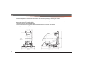
User Manual
Phoenix 20 Walk-Behind Scrubber
Traction Drive Cylindrical Deck
This manual is furnished with each new Phoenix 20. This provides the necessary operating and preventive maintenance
instructions. Operators must read and understand this manual before operating or servicing this machine.
This machine was designed to give you excellent performance and efficiency. For best results and minimal cost,
please follow the general guidelines below:
· Operate the machine with reasonable care.
· Follow the manufacturer’s suggested maintenance instructions as provided in this booklet.
· Use original Minuteman supplied parts.
2
Technical Specifications
Model
Phoenix 20 Traction Drive Cylindrical
Model No.
PHX20CQP / PHX20CQPG / 3336074QP
Current (Max)
Battery Capacity (Lead Acid)
Battery Capacity (Gel)
Sound Level
Cleaning path width
Squeegee width
Productivity
Working speed
Transport Speed
Rated voltage
Vacuum flow
Vacuum waterlift
Vacuum power
Brush type
Brush motor(s) power
Number of brushes
Brush RPM
Solution capacity
Recovery capacity
Working Grade
Weight with batteries
Weight without batteries
Dimensions (LxWxH)
Drive Motor Power
40 amps
140Ah @20 hr
100Ah @20 hr
69 dBA
20 in (51 cm)
34 in (86 cm)
27,280 ft 2 /hr ( 2,534 m2)
3.1 mph (5 km/hr)
3 mph (4.8 km/hr)
24 volts
65 cfm (110 m3/hr)
45 inches ( 112mbar)
.60 HP (450 W)
Cylindrical
3/4 HP (550W)
2
600 RPM
12Gal (45 liters)
13 Gal (49 liters)
2%
370lbs (168 kg)
235 lbs (107 kg)
44.5 x 24.0 x 38.0 (112.8 x 47.8 x 107.4 cm)
1/5 HP (150W)
3
Safety Instruction
Unpacking Instru
Inspection ............
Electrical ..............
Batteries ..............
Operator Respons
Machine Overview
Controls ...............
Bail Handle ..
Handle Adjus
Key Switch ..
Direction Swi
Squeegee Lif
Battery / Fau
Speed Contro
Charge Statu
Optional Hour Met
Circuit Breakers ...
Battery Compartm
Diagnostic Code G
Machine Overview
Handle Adjustmen
Angle Adjustm
Horizontal Ad
Solution Tank Drai
Solution Level Ind
Solution Fill Filter .
Screened Float ....
Screened Flo
In-Line Solution Fi
Rear Squeegee ...
4
Table Of Contents
Safety Instructions ...................................................................................... 6
Unpacking Instructions .............................................................................. 7
Inspection ...................................................................................................... 7
Electrical ........................................................................................................ 7
Batteries ........................................................................................................ 7
Operator Responsibility ................................................................................. 7
Machine Overview ....................................................................................... 8
Controls ....................................................................................................... 10
Bail Handle .......................................................................................... 11
Handle Adjustment Knobs ................................................................... 11
Key Switch .......................................................................................... 11
Direction Switch .................................................................................. 11
Squeegee Lift Lever ............................................................................ 11
Battery / Fault Gauge .......................................................................... 11
Speed Control ..................................................................................... 11
Charge Status Indicator ...................................................................... 11
Optional Hour Meter .................................................................................... 12
Circuit Breakers ........................................................................................... 13
Battery Compartment .................................................................................. 14
Diagnostic Code Guide ............................................................................... 15
Machine Overview ....................................................................................... 15
Handle Adjustment ...................................................................................... 16
Angle Adjustment ................................................................................ 16
Horizontal Adjustment ......................................................................... 17
Solution Tank Drain Hose ............................................................................ 18
Solution Level Indicator ............................................................................... 18
Solution Fill Filter ......................................................................................... 19
Screened Float ............................................................................................ 20
Screened Float Removal .................................................................... 21
In-Line Solution Filter Assembly .................................................................. 22
Rear Squeegee ........................................................................................... 23
Cleaning the Squeegee ...................................................................... 23
Changing the Squeegee Blades ......................................................... 23
Squeegee Blades ................................................................................ 24
Angle Adjustment ................................................................................ 24
Squeegee Blades ................................................................................ 25
Height Adjustment ............................................................................... 25
Brush Deck Maintenance ............................................................................ 26
Brush Loading / Unloading .......................................................................... 27
Brush Deck Maintenance ............................................................................ 27
The Phoenix 20 Cylindrical ....................................................................... 28
Machine Operation .................................................................................... 30
To Turn ON Machine: .................................................................................. 30
To Turn ON Vacuum: ................................................................................... 30
To Turn ON Brush Motor: ............................................................................ 30
To Turn on Cleaning Solution: ..................................................................... 30
Direction Switch: .......................................................................................... 30
Speed control: ............................................................................................. 30
Driving: ........................................................................................................ 30
To Charge Batteries: .................................................................................... 31
Hour Meter (Optional): ................................................................................ 31
After Use ..................................................................................................... 32
Maintenance ............................................................................................... 33
Troubleshooting ........................................................................................ 36
Warranty ..................................................................................................... 38
5
Safety Instructions
IMPORTANT SAFETY INSTRUCTIONS
Operators must read and understand this manual before operating or maintaining this machine.
Do not operate this machine in flammable or explosive areas.
This machine is designed solely for scrubbing dirt and dust in an indoor environment. Minuteman does not recommend using this machine
in any other capacity.
The following information below may cause a potential hazard to the operator and equipment. Read this manual carefully and be aware
when these conditions can exist. Take necessary steps to locate all safety devices on the machine and train the personnel operating the
machine. Report any machine damage or faulty operation immediately. Do not use machine if it is not in proper operating condition.
FOR SAFETY DURING OPERATION
Keep hands and feet clear of moving parts while machine is in operation.
Make sure all safety devices are in place and operate properly. All covers, doors and latches must be closed and fastened before use.
During operation, attention should be paid to other persons in the work area and especially if small children are present.
Electric motors and components can cause an explosion when operated near explosive materials or vapor. Do not operate this machine
near flammable materials such as solvents, thinners, fuels, grain dust, etc.
Store or park this machine on a level surface only. To prevent unauthorized use, machine should be stored or parked with the key removed.
This machine is designed for level operation only. Do not operate on ramps or inclines greater than 2%.
This machine is not suitable for picking up hazardous dusts.
Use caution when moving this machine into areas that are below freezing temperatures. Any water in the tanks or hoses can cause damage
to the machine.
FOR SAFETY WHEN SERVICING or MAINTAINING MACHINE
Stop on level surface.
Disconnect the power to the machine by unplugging the red Battery connector located under the recovery tank near the batteries.
Avoid moving parts. Do not wear loose jackets, shirts, or sleeves when working on machine.
Avoid contact with battery acid. Battery acid can cause burns. When working on or around batteries, wear protective clothing and safety
glasses. Remove metal jewelry. Do not lay tools or metal objects on top of batteries.
Charging batteries generates explosive gasses.
Do not charge batteries when open flames or sparks are present. Do not smoke.
Make sure the charger is turned off before disconnecting it from the machine.
Charge the batteries in a well-ventilated area with the battery cover removed completely.
Do not clean machine with a pressure washer.
Authorized personnel must perform repairs and maintenance. Use Minuteman supplied replacement parts.
SAVE THESE INSTRUCTIONS
6
Unpacking Instructions
Inspection
Carefully unpack and inspect your Phoenix 20 Walk-Behind Scrubber for shipping damage. Follow unpacking instructions
on shipping pallet. Each unit has been tested and thoroughly inspected before shipment. Any damage is the responsibility of
the delivery carrier who should be notified immediately.
Electrical
This machine is battery operated and designed to operate on 24 volts DC (2) 12-volt batteries.
Batteries
The recommended batteries are rated 140Ah WET (PowerBoss P/N 956140) or 100Ah MAINTENANCE FREE GEL (PowerBoss
P/N 956100). We do not recommend mixing AMP hour capacities. Alternate battery sets can be used if they equal physical
size and capacity. If alternate battery sets are used please contact PowerBoss for on board charger settings.
Operator Responsibility
Read this manual carefully before operating this machine.
The operator is responsible for taking care of the daily maintenance and check ups of the machine to keep it in good
working condition. The operator must inform the service mechanic or supervisor when the scheduled maintenance intervals
are required as stated in the MAINTENANCE section of this manual.
Before starting familiarize yourself with the machine and its controls (see “Machine Overview, Front”, “Machine Overview,
Rear”, “Control Console” diagrams).
7
Machine Overview
Machine Overview - Front
A
B
C
D
E
F
G
H
CUP HOLDER
SOLUTION FILL PORT
RECOVERY TANK LID
RECOVERY TANK
BRUSH DECK
FRONT WHEEL (see note)
REAR CASTER
SOLUTION TANK
* NOTE - Front tires are foam filled to be maintenance-free. No air can be added.
8
Machine Overview
Machine Overview - Rear
A
B
C
D
E
F
BAIL HANDLE
SQUEEGEE LIFT LEVER
RECOVERY TANK DRAIN HOSE
ONBOARD CHARGER CORD
CIRCUIT BREAKERS
RECOVERY HOSE
G
H
I
J
K
L
CONTROL PANEL
SOLUTION TANK DRAIN HOSE / LEVEL INDICATOR
BRUSH LIFT PEDAL
REAR SQUEEGEE
DIAGNOSTIC CODE GUIDE
SOLUTION CONTROL LEVER
9
Machine Overview
Controls
A
B
C
D
E
F
G
H
I
BAIL HANDLE
HANDLE ADJUSTMENT KNOB
KEY SWITCH
DIRECTION SWITCH
SQUEEGEE LIFT LEVER
BATTERY / FAULT GAUGE
SPEED CONTROL
CHARGE STATUS INDICATOR
SOLUTION CONTROL LEVER
A
C
D
E
B
G
F
I
10
H
Machine Overview
Bail Handle
(A) When the scrub deck is lowered to the floor, the bail handle enables the brush motor and moves the machine forward once
depressed.
Handle Adjustment Knobs
(B) Allows the handle position to be raised or lowered.
Key Switch
(C) Controls the machine’s power (Off/On) with a key for safety. When it is turned to the on position, the machine will operate.
Direction Switch
(D) This 3 position switch sets the direction the machine will move when the bail handle is pulled. The middle position is neutral brushes & vacuum will operate but machine will not move.
Squeegee Lift Lever
(E) When moved to the top position, the squeegee is lowered and the vacuum motor is turned on. When locked in the bottom
position, the squeegee is raised and the vacuum motor shuts off (after 10 second delay).
Battery / Fault Gauge
(F) This gauge displays the remaining battery charge. This gauge also displays any fault codes that might occur with the Drive Motor
Controller (see Diagnostic Codes).
Speed Control
(G) This control sets the speed at which the machine will move.
Charge Status Indicator
(H) This gauge displays the status of the batteries during charging. The gauge has a readout of 3 LEDs. 1 Green, 1 yellow, 1 Red.
Green indicating a full charge, Yellow indicating 80% charged, Red indicating the batteries are charging.
Solution Control Lever
(I) This lever controls the rate at which solution is dispensed. Moving the lever up will increase the amount of solution. Moving the
lever down will decrease the amount. Moving the lever all the way down shuts off solution flow.
11
Machine Overview
Optional Hour Meter
Powerboss offers an optional hour meter for the
Phoenix 20. The optional kit replaces the power
cord mounting bracket at the rear of the machine
with one that contains an hour meter, which
records the brush motor operating time.
Kit# K-E1720HM
12
Machine Overview
Circuit Breakers
The circuit breakers are located at the bottom of the back
panel of the machine.
A
B
C
D
Main Control Circuit Breaker - 4A
Brush Motor Circuit Breaker - 30A
Vacuum Motor Circuit Breaker - 20A
Drive Motor Circuit Breaker - 20A
If any of the functions above are not operating, check if the
circuit breaker buttons have tripped. Press to reset.
A
B
C
D
13
Machine Overview
Battery Compartment
The battery compartment is located under the recovery tank. The
Battery compartment can be accessed for servicing and maintenance by tilting the recovery tank (make sure recovery tank has
been drained before tilting). The battery compartment contains
two 12-volt batteries connected in series. Connect the batteries
according to the battery connection diagram (see diagram). The
recommended batteries are 140Ah (PowerBoss P/N 956140) or
95Ah (PowerBoss P/N 956100) Gel. The battery tray may be
drained if necessary using the orange drain hose located above
the rear caster on the right side of the machine.
14
Machine Overview
Diagnostic Code Guide
When an error or fault occurs within the machine, a fault
code will appear on the battery gauge represented by a
specified number of flashing LEDs. (See “Troubleshooting”
for further information)
15
Machine Overview
Handle Adjustment
The Phoenix 20 handle was designed with operator comfort in mind.
The angle and horizontal position of the handle can be adjusted to
suit the needs of the operator.
Angle Adjustment
The handle angle can be adjusted without tools by loosening the
Angle Adjustment Knob (A) on each side and rotating the handle
to the desired position. There are 5 angular positions 11.25° apart
for a total of 45° between the minimum and maximum position.
A
16
Machine Overview
Horizontal Adjustment
The horizontal position can be adjusted by removing the 4 Mounting
Bolts (B) (2 each side) with a 9/16” socket and sliding the Mounting
Plate (P) to one of the 3 available positions. The machine is shipped
from the factory in position 1.
3
P
Plate Position 3
(Fully Extended)
Plate Position 2
2
1
B
Plate Position 1
(Shipping Position)
17
Machine Overview
Solution Tank Drain Hose
The solution tank may be drained by removing the Solution Tank Drain
Hose (A) from the Hose Barb (B) and routing the hose to a floor drain.
B
A
Solution Level Indicator
The Solution Tank Drain Hose also serves as a water level indicator for
the solution tank. The amount of water remaining in the solution tank
can be seen through the clear drain hose. Level markers molded into
the solution tank are positioned at 1/4, 1/2, 3/4, and full levels.
18
Machine Overview
A
Solution Fill Filter
The Solution Fill Filter (B) should be cleaned regularly.
To remove, simply open the Solution Tank Lid (A) and
pull the filter out.
B
Recovery Tank Drain Hose
Twist Cap to Open and Drain
Twist & Lift cap to clean out
large debris
19
Machine Overview
Screened Float
If the recovery tank (C) is overfilled or a large amount of foaming is
present, the screened float (B) blocks the vacuum intake inside the
tank protecting the vacuum motor and internal electronics from water
damage. It is essential to keep the float in working order through
regular maintenance.
A
B
The float should be cleaned daily by thoroughly rinsing with a hose.
Removal of the screened float is not necessary for daily maintenance.
C
At least once a month the screened float should be completely
removed, cleaned, and checked for any damage to the seal or metal
screen.
WARNING: Damage to the machine may occur if operated
without the screened float properly in place.
20
Machine Overview
Screened Float Removal
D
E
The screened float is positioned between the vacuum manifold (A)
and recovery tank (C). The screened float (B) can be accessed by
removing the 1.5” bolt (D) and two 1.25” bolts (E) that attach the
manifold to the recovery tank using a 7/16” socket.
E
F
G
A
B
C
D
E
F
G
A
Vacuum Manifold
Screened Float
Recovery Tank
1.5” Bolt
1.25” Bolt (2)
Helical Washer (3)
Flat Washer (3)
B
21
Machine Overview
In-Line Solution Filter Assembly
The pump and solution solenoid, which shuts off solution flow when the bail handle is released, are protected from debris by the in-line filter
assembly. The filter assembly is located at the front of the machine above the brush deck. It is important to check and clean the screened
washer inside the assembly regularly to ensure proper solution flow. After shutting off solution flow, unscrew the assembly (Note that the cone
of the washer is facing away from the pump). Remove washer and rinse, reinsert and screw assembly together, tightening by hand. Overtightening
with tools may damage the plastic threads.
A
B
C
D
22
Fitting, MGHT
Screened Washer
Hose Barb Insert
Fitting, FGHT
Machine Overview
Rear Squeegee
Cleaning the Squeegee
Changing the Squeegee Blades
A
B
C
D
E
F
G
Check the squeegee (A) daily and clean as
necessary.
1. Pull off the suction hose (D).
2. loosen the two star-shaped knobs (B).
3. Remove the squeegee (A).
Check the inner and outer squeegee blades on
the squeegee (A) weekly for signs of wear. The
squeegee blades can be reused by turning them
(can be turned for 4 total uses).
1. Pull off the suction hose (D), loosen the two starshaped knobs (B) and remove the squeegee.
2. Unlock the fastening device (E) and remove the
outer squeegee blade. Turn the squeegee blade
or install a new one, as necessary. Change the
Squeegee
Star-shaped knob
Adjusting screw for angle adjustment
Suction hose
Blade fastening latch
Washers for caster height adjustment
Caster Wheel Axle
inner squeegee blade in the same way.
23
Machine Overview
Squeegee Blades
Angle Adjustment
The angle adjustment is the decisive factor in
ensuring that the squeegee blades on the
squeegee lie evenly on the floor.
1. Park the machine on a level surface and lower
the squeegee.
2. Loosen the lower wing nut (B) on the adjusting screw (C) and adjust the squeegee using
the adjusting screw so that the ends of the
squeegee blades still have contact with the
floor. By turning the adjusting screw (C) counterclockwise, the clearance between squeegee
blade and floor is increased in the center (Fig.
1). When turning the adjusting screw (C) clockwise, the clearance between squeegee blade
and floor is reduced in the center (Fig. 2).
3. Switch the machine on and check the suction
pattern. When the machine is in operation, the
entire surface of the squeegee blades (center
and outer areas) must be applied as evenly as
possible.
4. Tighten the lower wing nut (B) on the adjusting screw (C) against the metal bracket to lock
in the pitch setting.
24
1
B
A
2
B
A
Machine Overview
Squeegee Blades
Height Adjustment
If streaks are present, despite an optimum
angle adjustment, the clearance between the
caster wheels and floor must be adjusted by
changing the number of washers underneath
the bracket that holds the wheel. The
squeegee height is preset at the factory to
3mm.
3 mm
2 mm
4 mm
In cases of very smooth floors, e.g. finished
floors, PVC, linoleum, etc., see 2mm
illustration for washer configuration.
In cases of very uneven floors, e.g. poorly laid
tiles (water does not run off) ,, configure as
shown in 4mm illustration.
Keep the extra washers by
installing them above the bracket
as shown.
25
Machine Overview
Brush Deck Maintenance
Sprayjet Maintenance
The sprayjets deliver solution to the floor. The spray tip should be cleaned weekly to ensure good cleaning results.
To Install
Figure 1
Figure 2
Figure 3
Spray tip removal and installation for cleaning
1. Remove knob located above sprayjet (Figure 1).
2. Pull sprayjet cover up and hold for easy access to spray tip (Figure 2).
3. Remove spray tip by hand by pushing the tip up into the nozzle body and rotate 1/4 turn clockwise (Figure 3).
4. Reinstall by pushing spray tip up into the nozzle body and rotate 1/4 turn counterclockwise until tip will not turn (Figure 3).
NOTE: Ensure that the tip is facing toward the deck.
26
To Remove
Machine Overview
Brush Deck Maintenance
Debris Tray Maintenance
The Debris Tray (A) collects debris from the floor during operation. It must be cleaned
regularly. Remove the tray from the deck by tilting the bottom up, then sliding it out to the
side. Empty the tray and rinse it. Return the tray by sliding the top edge into the channel
along the top-rear corner of the deck. The tray will fall into place when fully inserted.
Brush Loading / Unloading
1. Raise brush deck. Unscrew the
knob on the right side of the deck
as shown above. Pull open the
Hinged Cover (A).
2. The drive side of each brush has a
black end-cap with teeth. Insert the
drive side of the brush through the
opening until engaged on to the
Drive Hub (B).
3. Insert Idle Hubs (C) into the
brushes while closing the hinged
cover. Tighten the knob on the
cover by hand, ensuring that the
hinged idle cover is flush to the
deck.
27
The Phoenix 20 Cylindrical
This machine was designed with total operator comfort and ease of use in mind. All machine components have been designed
as a total system to efficiently clean dirty floors. Please contact your PowerBoss representative for specific recommendations
for the correct brush type and chemical applications.
Before using the machine, always perform the following steps to ensure proper machine operation:
• Check under the machine for leaks.
• Check the rear squeegee for wear and damage.
• Check the solution and recovery tank levels.
After using the machine, always perform the following steps:
• Check the battery charge level. Charge batteries if necessary. When charging batteries, extra precaution is required:
- Battery acid can cause burns.
- When working on or around batteries, always wear protective clothing and safety glasses.
- Remove metal jewelry. Do not lay tools or metal objects on top of the batteries.
- Charging batteries generate explosive gasses.
DO NOT CHARGE BATTERIES WHEN OPEN FLAMES OR SPARKS ARE PRESENT. DO NOT SMOKE.
- Charge the batteries in a well-ventilated area.
- Fluid levels should be checked before and after charging and maintained at the proper levels. If low, add distilled water until
the metal plates are covered.
- If the machine is not used for an extended period of time, batteries should be kept fully charged with a boost charge once a
week.
• Check for wire, string, or twine wrapped around the scrub brushes.
• Check the rear squeegee for wear and damage.
• Check the rear squeegee suction hose for obstructions.
• Drain and rinse the recovery tank.
• Check under the machine for leaks.
• Check the service records to determine maintenance requirements.
28
The Phoenix 20 Cylindrical
WARNING!
- Be sure you understand the machine controls and their functions.
- While on ramps or inclines, avoid sudden stops when tanks are filled.
- Avoid abrupt sharp turns. Slow down driving speed when going downhill.
29
Machine Operation
Machine Operation
To Turn ON Machine:
Turn key to operate position ( I ). Wait for battery gauge to stop flashing. (If flashing continues, see troubleshooting guide)
To Turn ON Vacuum:
Lower squeegee into operating position, vacuum motor will turn ON automatically.
To Turn ON Brush Motor:
Lower the scrub deck to the floor by moving the brush lift pedal from the “home” (down) position to the operating position (up).
Depress the operator bail handle. Brush motor will turn ON.
To Turn on Cleaning Solution:
Move solution lever from closed (down) position up to the desired flow position. With the scrub deck on the floor, depress the
bail handle, solution will begin to flow.
Note: The solution solenoid will stop solution flow whenever the bail handle is released.
Direction Switch:
Select direction of machine by moving the directional rocker switch from the neutral position to the forward or reverse position.
The direction of the machine movement is shown on the operator panel with forward and reverse arrows.
Speed control:
Move the speed dial to the desired position. Turning the dial clockwise increases the speed. Turning the dial counterclockwise
decreases the speed.
Driving:
Depress the operator bail handle, the machine will move in the direction selected.
30
Machine Operation
To Charge Batteries:
When the battery / fault gauge reaches the red zone the batteries need to be recharged. Take the machine to a well ventilated
area, unwind the battery charger power cord from the electrical box cover and plug into an appropriate power source. After
approximately 10 seconds the battery charge status indicator will turn on. Check the battery water levels before each use, refill as
needed with distilled water. Caution: do not overfill. Fill water 1/4 “ - 1/2” above the separators. Failure to maintain the
batteries may result in battery failures.
WARNING: Charging batteries generates explosive gasses. Do not charge batteries when open flames or sparks are
present. Do not smoke. Charge the batteries in a well-ventilated area .
Hour Meter (Optional):
Hour meter will automatically record operating time of the brush motor.
31
After Use
1. When finished scrubbing, lift the scrub deck. Lift the rear squeegee (the vacuum motor will turn off after 10 seconds).
Move the machine to a service area for daily maintenance and review items that may need service.
2. Remove debris tray from the brush deck, cleanout and rinse.
3. Empty the solution tank by disconnecting the solution tank drain hose from the barb fitting and routing hose to a
drain. Rinse the tank with clean water to prevent any buildup of dried chemicals that could clog the plumbing.
4. Empty and clean the recovery tank by flushing with a hose. Be sure to also clean the float shut off screen.
5. Remove the brush and rinse it in warm water and hang to dry.
6. Remove the rear squeegee and recovery hose, rinse with warm water and reinstall after cleaning.
7. Check the maintenance schedule in the next section and perform any required maintenance before storing the
machine.
8. Store the machine indoors in a clean dry place. Keep from freezing. Leave solution and recovery tank lids open for
ventilation to prevent odor buildup.
9. Turn Key switch OFF (O) and remove key.
32
Maintenance
D a i ly
C h a rg e B a tt e r ie s
C h e ck /C lea n T a nk s &
H oses
C h e ck /C lea n Br us h
C h e ck /C lea n th e
S q u e e ge e
C h e ck /C lea n Va cu um
S h u t- O f f F lo at in
R e c o v er y T a n k
C le a n th e b ru sh d e c k
d e br is tra y.
W e ek l y
I ns p ec t B ru sh
D e ck S id e S kir ts
f or D e b r is
I ns p ec t a n d
C le an I n- L ine
S o lut io n F ilt e r
R in se o ff t he
u n d er sid e of
br u s h d ec k
Ch eck E ach
B a t te ry C e ll( s)
W a t er Le ve l
I ns p ec t a n d
C le an s p ra y jet
t ip
M o n th l y
L u b r ica tio n –
G re a se F it tin g s
Y e a rl y
C h ec k C ar b on
B ru sh es
/
Have a qualified service technician check the vacuum motor carbon motor brushes once a year or after 300 operating hours.
The brush motor and transaxle motor carbon brushes should be checked every 500 hours or once a year.
NOTE: Refer to the Service Manual for more detail on maintenance and service repairs.
Regularly scheduled lubrication of certain machine parts should be performed to insure trouble-free operation of the
machine. Apply a generous amount of grease into the fittings on the rear caster swivel (2) until grease seeps out around the
bearings.
Apply lubricant or light machine oil to lubricate the:
• Pivot mounting point of the rear squeegee to the chassis (1)
• Rear squeegee caster wheel axle (2)
33
Troubleshooting
Prob lem
Po or water p ic k-up
Po or scrubb ing perfo rm an ce
I nadequate so lutio n fl ow o r
n o solution to th e floor
M achin e does not m ove
Brush deck vib ratio n
34
Possi ble Cau se
Worn or torn squeegee blades
Recovery t ank full
Recovery t ank drain hose leak
Recovery t ank lid gasket leak
Debris cau ght in squeegee
Recovery hose clogged
Recovery hose to squeegee or tank
disconnected or dama ged
Worn brushes
Wrong brush or cleaning chemic al
Debris cau ght on scrub brushes
Moving m achine too fast
Low battery charge
Not using enough solution
Solution tank empt y
Solution lines, filter or spray jet clogged
Brush m otor circuit breaker has tripped
Pum p m ay take up t o 1 minute to push
water aft er long periods of non-use
Solution Lever in down po sition
Squeegee is down and directional
switch is in reverse po sition
Traction drive circuit breaker has tripped
Bat teries lost power
Directional switch in neut ral position
Brushes m ay have flat spots from sit ting
for a long period of t im e on the floor
Debris in b rushes
Rem edy
Rot ate or rep lace blades
Em pty recovery tank
Secure drain hose cap or replace
Replace gasket lid cover properly
Clean squeegee
Rem ove debris and flush hose
Reconnect or replace recovery hose
Rot ate or rep lace brushes
Consult Manufacture r
Rem ove debris
Slow dow n
Recharge bat teries
Adjust solution flow setting
Fill solution tank
Flush lines, and clean solut ion filter and spray jet.
Reset circuit breaker
Run pump until solution flows.
Raise lever u p
Raise squeegee when in reverse mode
Reset circuit breaker
Recharge bat teries
Activate FW D or REV position
Rot ate one of the brushes in the deck. Use m ac hine
fo r 30 m inute s, flat spots will work t hemselves out.
Rem ove debris from brushes.
Troubleshooting
Problem
Machine does not operate
Possible Cause
Tripped Control Power circuit breaker
Batteries have low charge
Battery charger operating
Key switch off
Bail handle depressed too quickly after
turning key on
Recovery tank full
Excessive foaming in recovery tank.
Vacuum motor does not turn
on
Batteries do not charge
Squeegee in raised position
Tripped vacuum motor circuit breaker
Broken vacuum limit switch
Carbon Brushes worn
Vacuum switch disconnected
Charger not plugged to wall outlet
Circuit breaker tripped in wall outlet
Battery disconnected from machine
Charger malfunction
Charger Warning Indicators
LED Status
RED LED lamp blink
once
Warning
RED LED lamp blink
twice
Remedy
Reset circuit breaker
Recharge batteries
Unplug battery charger when charge is complete
Turn key on
Turn key off, turn on, wait until battery gauge
lights up without flashing
Empty recovery tank
Empty recovery tank.
Rinse off the screened float inside recovery tank.
Use less or change chemical.
Use de-foaming agent.
Lower squeegee
Reset breaker
Replace switch by squeegee lift lever
Replace carbon brushes
Connect wiring
Plug into wall outlet
Reset breaker
Connect battery to machine
Call service
Description
Output open circuit or short circuit or reverse polarity connection of charger to
battery. Battery voltage is too high (may be connected to wrong voltage battery).
Abnormal cycle (may be weak or bad battery)
Charging time has safety timed out due to battery problem.
35
Troubleshooting
Fault / Diagnostic Codes
The Battery / Fault gauge will flash when a fault is detected. A decal labeled “Diagnostic Codes” is located below the battery gauge as an abbreviated
and convenient guide to determine the cause of the fault and the remedy (refer to machine or see “Diagnostic Code Guide” section of this manual). The
flashing codes are for the following:
36
The battery needs charging, there is a bad
connection to the battery or dependent on
programming, may indicate that the battery
lockout function is active and the controller is
in a restricted mode of operation. Check the
connections to the battery. If the connections
are good, try charging the battery.
The motor has a short circuit to a battery
connection. Contact your service agent.
There is a bad connection to the motor. Check
all connections between the motor and the
controller.
The battery charge level has fallen below the
Battery Lockout level and the controller is
inhibiting certain machine functions. Charge
the battery.
Troubleshooting
Not used.
A controller fault is indicated. Make sure that
all connections are secure.
The controller is being inhibited from driving,
this may be because the battery charger is
connected.
Not used.
The bail handle was activated prior to turning
the machine on. Make sure that the bail handle
is in the rest position. Restart the key switch.
An excessive voltage has been applied to the
controller. This is usually caused by a poor
battery connection. Check the battery
connections.
37
PowerBoss Incorporated Made Simple Commercial Limited Warranty
Revision F
Effictive November 1, 2008
Powerboss made Simple Industrial Limited Warranty
Minuteman International owner of PowerBoss warrants to the original purchaser/user that the product is free from defects in workmanship
and materials under normal use. PowerBoss will, at its option, repair or replace without charge, parts that fail under normal use and service
when operated and maintained in accordance with the applicable operation and instruction manuals. All warranty claims must be submitted
through and approved by factory authorized repair stations.
This warranty does not apply to normal wear, or to items whose life is dependent on their use and care. Parts not manufactured by
PowerBoss are covered by and subject to the warranties and/or guarantees of their manufacturers. Please contact Minuteman International
for procedures in warranty claims against these manufacturers.
Special warning to purchaser — Use of replacement parts not manufactured by PowerBoss or its designated licensees, will void all
warranties expressed or implied. A potential health hazard exits without original equipment replacement.
All warranted items become the sole property of Minuteman International or PowerBoss or its original manufacturer, whichever the case
may be.
PowerBoss disclaims any implied warranty, including the warranty of merchantability and the warranty of fitness for a particular purpose.
PowerBoss assumes no responsibility for any special, incidental or consequential damages.
This limited warranty is applicable only in the U.S.A. and Canada, and is extended only to the original user/purchaser of this product.
Customers outside the U.S.A. and Canada should contact their local distributor for export warranty policies. PowerBoss is not responsible
for costs or repairs performed by persons other than those specifically authorized by PowerBoss. This warranty does not apply to damage
from transportation, alterations by unauthorized persons, misuse or abuse of the equipment, use of non-compatible chemicals, or damage
to property, or loss of income due to malfunctions of the product. If a difficulty develops with this machine, you should contact the dealer
from whom it was purchased.
This warranty gives you specific legal rights, and you may have other rights, which vary from state to state. Some states do not allow the
exclusion or limitation of special, incidental or consequential damages, or limitations on how long an implied warranty lasts, so the above
exclusions and limitations may not apply to you.
38
Travel*
Labor
Parts
Engine
Extended Warranty
Battery sweepers
Ninety days
One year
One year
N/A
2 years Parts + Labor (or 2000 Hours)
IC sweepers
Ninety days
One year
One year
Through manufacturer
2 years Parts + Labor (or 2000 Hours)
Battery scrubbers
Ninety days
Two years
Three years
N/A
3 Years Parts + Labor (or 3000 Hours)
Costs
Walk behinds
2%
2%
2%
Riders
Battery scrubbers
Ninety days
Two years
Three years/2000 hrs
N/A
3 Years Parts + Labor (or 3000 Hours)
IC sweeper/scrubbers
Ninety days
Six months
Two years/2000 hrs
Two years/3000 hrs**
IC sweepers
Ninety days
Six months
Four years/3000 hrs
Five years/3000 hrs**
2 years Parts + Labor (or 2000 Hours)
4 Years Parts + 2 Years Labor (or 4000
Hours)
Apex series sweeper
Ninety days
One year
One year/1000 hrs
One year/1000 hrs**
2 years Parts + Labor (or 2000 Hours)
6X sweeper
Ninety days
Six months
Two years/2000 hrs
Two years/2000 hours**
2 years Parts + Labor (or 2000 Hours)
2%
3%
3%
Exceptions
3%
3%
Tank Bladders
Eight years/ no additional labor
Polypropylene plastic tanks Ten years/ no additional labor
Batteries
0-3 months full replacement, 4-12 prorated credit
Chargers
One-year replacement
Replacement parts
Ninety days
*Two-hour cap
**Through engine manufacturer. See section 3 of warranty manual for engine warranty exceptions
*** Based upon dealer’s certification status
Extended Warranty MUST be signed up within 30 days of delivery to End User (Dealer has 1Year from Receiving Machine to Sign up
extended Warranty)
Extended Warranty Cost is based on Invoice Price multiplied by the Percentage listed in the Extended Warranty Column
39
PowerBoss Incorporated · 175 Anderson Street P.O. Box 1227 · Aberdeen, North Carolina 28315
Phone: 1-800-982-7141 · Fax: 1-800-277-7141 · Local: 1-910-944-7409
www.powerboss.com
A Member of the Hako Group
988728UMPB
Rev B 04/10