1
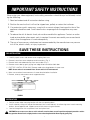
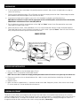
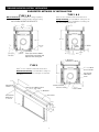
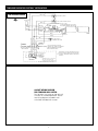
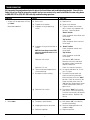
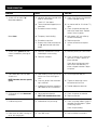
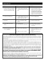
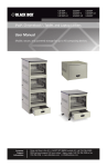
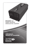
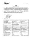
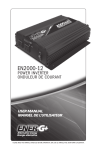
The Da-Lite Difference. Instruction Book for Tensioned Executive Electrol® DA-LITE SCREEN COMPANY, INC. 3100 North Detroit Street Post Office Box 137 Warsaw, Indiana 46581-0137 Phone: 574-267-8101 800-622-3737 Fax: 574-267-7804 www.da-lite.com e-mail: [email protected] IMPORTANT SAFETY INSTRUCTIONS When using your video equipment, basic safety precautions should always be followed, including the following: 1.Read and understand all instructions before using. 2.Position the cord so that it will not be tripped over, pulled, or contact hot surfaces. 3.If an extension cord is necessary, a cord with a current rating at least equal to that of the appliance should be used. Cords rated for less amperage than the appliance may overheat. 4.To reduce the risk of electric shock, do not disassemble this appliance. Contact an authorized service dealer when repair work is required. Incorrect reassembly can cause electric shock when the appliance is used subsequently. 5.The use of an accessory attachment not recommended by the manufacturer may cause a risk of fire, electric shock, or injury to persons. SAVE THESE INSTRUCTIONS PRE-INSTALLATION 1. Carefully unpack screen and remove outer wrapping from case. 2. Remove instructions cover and please read instructions. (Fig. 1) 3. Remove fabric and cardboard strips from access door. (Fig. 1) 4. Remove access door by gently prying from edge of box toward the fabric door. 5. FOR TYPE 3 INSTALLATION ONLY. Remove wood strips along bottom of screen case. NOTE: Screen surface is not centered in box. Screen surface is 25" from motor end. 6. Make sure to recheck measurements of screen location before installation. 7. Remove, reverse, and remount center support brackets. CASE ACCESS DOOR FABRIC DOOR FABRIC STRIP CARDBOARD STRIP INSTRUCTION COVER FIGURE 1 INSTALLATION 1. Position screen under mounting location with the case opening down. 2. Install screen by raising unit into position between joists at one end only. Install one lag screw in each mounting bracket. Secure opposite end. Support center of the screen using the brackets. 3. Level unit lengthwise with a carpenter’s level and a plum level. ! s CAUTION! Do not secure access door or seal in unit until screen has been secured in position and properly tested for satisfac- tory operation. Do not fit unit so tightly that the screen surface drop door binds. Door drops by gravity only. 1 INSTALLATION 4. If you are going to cover screen door with paneling or other materials, allow access (suitable holes or a plug) to screws for servicing. 5. P icture surface should hang freely. (Fig. 2) Remove any tape left hanging on back of fabric. Bottom edge should be positioned between bottom edge of case and center of roller. 6. Install electrical hook up that applies to your unit. Unit should be installed by a qualified electrician. NOTE: Must be installed in accordance with the requirements of the Local Building Codes, the Canadian Electrical Code (CEC), CAN/CSA C22.1 and the National Electric Code (NEC), NFPA 70. 7. T est installation by carefully running picture surface “up” and “down” several times. Be prepared to stop screen. Fabric door must open freely to 90˚. 8. M ake sure picture surface, when rolled down, has a full wrap around roller. No part of roller should be exposed. Fabric door and picture surface will drop simultaneously when switch is pressed “down”. Door will close simultaneously with picture surface as picture surface rolls into case. CROSS SECTION FALSE TOP BUMPER BRACKET ACCESS PANEL SCREW (PAINTED) PICTURE SURFACE ACCESS PANEL CLIP FABRIC DOOR ACCESS PANEL FIGURE 2 ACCESS DOOR INSTALLATION 1. Press switch “down” so that fabric door opens (Fig. 2). 2. Remove screws (2) located on each bumper bracket. NOTE: The access door is slotted on one edge, permitting the slotted section to fit over the access panel clips on inside of case. 3. P lace access panel so slot can be pushed over clips. Holes in access panel brackets should align with bumper bracket holes. 4. Replace screws. 5. M ake sure there is approximately 3⁄16" clearance around access door. Keep paint, plaster, tile or mastic out of hinge. Fit access panel so it can be removed for maintenance. SCREEN ADJUSTMENT The picture surface drop, and the opening and closing of the fabric door, are controlled automatically by limit switches which have been preset at Da-Lite. When the picture surface is moving upward, it is controlled by a limit switch that shuts off when the door closes. The height for tensioned screens are adjusted at Da-Lite, changing the height of screen will change the tension on fabric and cause the screen to hang improperly. Do not adjust. 2 TENSIONED EXECUTIVE ELECTROL® INSTALLATION Suggested Methods of Installation Type 1 & 2 Type 1 & 2 Allow ⁄8" min. clearance all around surface door. Offset mounting, recessed above ceiling, for plaster, dry wall or paneling. Door painted same finish as ceiling. 1 Flush mounting, recessed above ceiling. For use with 1⁄4" max. paneling or installation in existing ceiling using molding around door. INCLUDING MOUNTING BRACKETS 9 7⁄8" 9 1⁄2" 8" ⁄4" 3 3" False Top False Top 12 1⁄16" 12 1⁄16" ⁄4" Picture Surface CEILING TILE 3 ⁄4" 2 1⁄2" 1 ⁄8" Approx. NOTE: Paint the same as doors and ceiling or remove and replace with ceiling tile. 3 FILLER BLOCK 1 1 ⁄4" MAX. ⁄8" 4 3⁄4" “L” BRACKET DRYWALL Screw Type 3 Allow 1⁄4" min. clearance all around surface door. ⁄4" x 1" SCREW & NUT INSERT 1 False Top Extended mounting, recessed above ceiling. For use with acoustical or other ceiling tile 3⁄4" thick laid over door. 11 5⁄16" Mounting Brackets SHIM 3 1⁄2" Surface Door ELECTRICAL OUTLET LENGTH OF FABRIC WIDTH + 28 3⁄4", ALL SIZES “L” BRACKET Access Door FALSE TOP MOUNTING BRACKETS 3 ⁄16" THICK 2 3⁄16" 22" 12 1⁄16" 9 ⁄2" 1 4 1⁄2" 3 ⁄4" x 2" 1 Lag Screw ⁄4" 3 TENSIONED EXECUTIVE ELECTROL® INSTALLATION 120V WIRING DIAGRAM BLACK DOWN LIMIT SWITCH CAPACITOR DOOR SOLENOID LIMIT SWITCH BLUE RED (UP) BLACK MOTOR: 120V.60 CYCLES 1/10 HP INTERMITTENT DUTY WITH AUTO-RESET THERMAL PROTECTOR DOWN ADJ. WHITE BLACK BLACK (DOWN) BLUE SOLENOID UP RED (UP) BLACK UP LIMIT SWITCH (OPERATED BY DOOR) GREEN (GROUND) JUNCTION BOX, MOUNTED IN SCREEN CASE, IN WHICH INTERNAL WIRING TERMINATES IN WHITE, BLACK AND RED LEADS RED BLACK (DOWN) RED WHITE EXTERNAL WIRING TO BE COMPLETED BY INSTALLER BLACK INTERNAL WIRING WHITE (COMMON) WHITE BLACK WITH YELLOW AC COMMON AC HOT OFF DOWN SIDE VIEW OF SWITCH & BOX 120VAC 60HZ. 1 AMP. MAX OPERATING SWITCH, SWITCH BOX, AND PLATE FURNISHED WITH SCREEN. (SPDT) WITH CENTER OFF) IN MULTIPLE CONTROL INSTALLATIONS THIS SWITCH IS REPLACED BY THE LOW-VOLTAGE CONTROL, OPERATED FROM PUSH-BUTTON STATIONS. THIS SWITCH CANNOT BE USED WITH L.V.C. 240 VOLT WIRING DIAGRAM FOR STANDARD WALL SWITCH: Da-Lite offers two styles of 240 volt wall switches for standard operation. Please see wiring diagram included in wall switch box included with screen. 4 TROUBLESHOOTING Visit www.da-lite.com/products/tutorials.php to find installation and troubleshooting tutorials. You will also find a link to Live Chat for interactive support and you can contact us by email at [email protected] or by phone at (800) 622-3737 or (574) 267-8101 with any troubleshooting questions. Symptom Cause Solution 1. S creen will not operate or will not go “down”. (a) Blown fuse. (a) Replace fuse. Motor does not hum. (b) Tripped circuit breaker. (b) Reset circuit breaker. (c) Improper wiring to operating switch. (c) T ighten all loose wire connections. Correct any improper connections. Check for power. (d) Improper wiring to junction box in screen. NOTE: Use low voltage control (LVC) electrical checklist for either 1- or 3button control. Defective wall switch. Defective LVC unit. “Down” Position heck for power across black and C white leads. “Up” Position heck for power across red and C white leads. (d) “Down” Position heck for power at black and C white leads. “Up” Position heck for power at red and C white leads. hut power “off” at breaker. S Remove wall switch and check for broken or loose connection. Replace if defective. Check LVC electrical checklist. (e) T hermal overload tripped (excessive overheating). (e) L et motor cool down for 15 minutes. Try again. (f) Burned out motor winding. (f) D isconnect motor leads and check for continuity between black and white wires for “down” position. Check for continuity between red and white wires for “up” position. Replace gear motor if either combination shows an open circuit. (g) Defective limit switch. (g) D isconnect “down” limit switch from circuit. Check for continuity. Switches are normally closed and open on contact. Replace if defective. (a) Temporary fabric binding. (a) W ith power “off,” turn roller by hand to free binding. (b) Shipping bracket not removed. (b) R emove shipping bracket and wooden wedge. (c) Defective capacitor. (c) Replace capacitor 2. Motor hums. 5 TROUBLESHOOTING Symptom Cause Solution 3. Screen will not move “up.” (a) N o power between red and white leads in junction box. (a) C heck fuse. Reset circuit breaker. Correct improper wiring. Motor does not hum. Motor hums. 4. S creen starts upward and door closes immediately shutting off motor. Check LVC. See above. (b) T hermal overload tripped (acts as a breaker). (b) L et motor cool for 15 minutes. Try again. (c) Burned out motor winding. (c) C heck for power between red and white motor leads. Replace motor if there is power. (d) Temporary fabric binding. (d) With power “off,” turn roller by hand to free binding. (e) Burned out capacitor. (e) Replace capacitor. (f) B roken wire or loose connection in “up” position (red and white leads). (f) S ecure connection or replace wire. (a) D efective solenoid limit switch. Solenoid pin not retracting. (a) Manually retract pin a few times. (b) Defective solenoid. (b) C heck for power to the solenoid terminals. If there is power, replace solenoid. 5. F abric door does not fully open. Screen runs. heck blue wire between soleC noid switch and solenoid. It is either crimped or broken. Repair or replace. (a) D oor binding. Plaster, paint or adhesive can cause the hinge to stick. (a) Clean hinge and apply oil. (b) C ase may be put into a bind during installation. (b) T ighten or loosen lag screws located on back of case. (c) Inadequate clearance around the fabric door on new installations. (c) Provide adequate clearance. 6. C licking noise in each downward revolution. (a) Non-energized solenoid. (a) Check for power to solenoid. 7. Loud buzzing noise. (a) Solenoid not fully retracting. N OTE: Remember, door must open by gravity. NOTE: There should be three clicks. (b) Replace solenoid. (a) C heck for foreign object caught in solenoid. Remove object. Tighten 4 mounting screws. 8. D oor closes on fabric, leaving 15" to 20" left hanging out. (a) Lost roller wrap. 6 Check for pin binding. (a) See installation instructions. TROUBLESHOOTING Symptom Cause Solution 9. S creen jammed. Will not operate, motor hums, door open, closing mechanism detached from door. (a) C losing mechanism detached from door, allowing it to jam into box. (a) After securing fabric to roller, loosen set screws on motor gear and manually rotate solenoid assembly back over top of roller into position, then reattach door. Match flats on motor drive shaft to gear set screws and tighten. 10. Scraping or grinding noise. (a) If metal shipping bracket is left attached to screen, it may be rubbing on motor end of roller. (a) Remove shipping brace. 11. Gear noise. (a) Gear may need light weight grease. (a) Apply light weight grease. 12. Incorrect down limit switch setting. (a) Lost roller wrap. (a) See installation instructions. (b) Limit switch out of adjustment. (b) S ee door closure and timing instructions. 13. Door closes and screen continues to run upward. (a) Door limit out of adjustment. (a) L oosen nut holding limit switch. Rotate adjusting position, then secure. (b) Door limit switch is shorted. (b) R epair short or replace limit switch. LIMITED ONE YEAR WARRANTY ON DA-LITE PRESENTATION PRODUCTS Da-Lite Screen Company, Inc. warrants its products to the original purchaser only, to be free from defects in materials and workmanship for a period of one (1) year from the date of purchase by the original purchaser provided they are properly operated according to Da-Lite’s instructions and are not damaged due to improper handling or treatment after shipment from the factory. This warranty does not apply to equipment showing evidence of misuse, abuse or accidental damage, or which has been tampered with or repaired by a person other than authorized Da-Lite personnel. Da-Lite’s sole obligation under this warranty shall be to repair or to replace (at Da-Lite’s option) the defective part of the merchandise. Returns for service should be made to your Da-Lite dealer. If it is necessary for the dealer to return the screen or part to Da-Lite, transportation expenses to and from Da-Lite are payable by the purchaser and Da-Lite is not responsible for damage in shipment. To protect yourself against damage or loss in transit, insure the product and prepay all transportation expenses. THIS WARRANTY IS IN LIEU OF ALL OTHER WARRANTIES, EXPRESS OR IMPLIED, INCLUDING WARRANTIES AS TO FITNESS FOR USE AND MERCHANT ABILITY. Any implied warranties of fitness for use, or merchantability, that may be mandated by statute or rule of law are limited to the one (1) year warranty period. This warranty gives you specific legal rights, and you may also have other rights, which vary from state-to-state. NO LIABILITY IS ASSUMED FOR EXPENSES OR DAMAGES RESULTING FROM INTERRUPTION IN OPERATION OF EQUIPMENT, OR FOR INCIDENTAL, DIRECT, OR CONSEQUENTIAL DAMAGES OF ANY NATURE. In the event that there is a defect in materials or workmanship of a Da-Lite product, you may contact our Sales Partners at PO Box 137, Warsaw, IN 46581-0137, (574) 267-8101, (800) 622-3737. IMPORTANT: THIS WARRANTY SHALL NOT BE VALID AND DA-LITE SHALL NOT BE BOUND BY THIS WARRANTY IF THE PRODUCT IS NOT OPERATED IN ACCORDANCE WITH DA-LITE’S WRITTEN INSTRUCTIONS. Keep your sales receipt to prove the date of purchase and your original ownership. Printed in U.S.A. 7 76359 Rev. 9/09