1
A Subsidiary of ITT
QumeTrak 842
Maintenance
December 1981
2350 Qume Drive
•
San Jose, California 95131
•
T'vVX
910~338·0232
•
(408) 942-4000
Reorder Number 36027
iCj1981 Qume Corporation
Oume, Qume Caribe Inc., 0, 030, 045, Sprint, Sprint 45, Sprint 55, Sprint 3, Sprint Micro
3, Sprint Micro 3/35, Sprint Micro 3/45, Sprint Micro 3/55, Sprint 5, Sprint Micro 5, Sprint
Micro 5/45, Sprint Micro 5/55, Sprint 5 WideTrack, Sprint 7 Series, Sprint 7/35, Sprint 7/45,
Sprint 7/55, Sprint 9 Series, Sprint 9/35, Sprint 9/45, Sprint 9/55, WideTrack, TwinTrack,
PHD, Speed Feed, SpeedFeed 5, Multifeed, Twintellect, Wedge, Activity Monitor, MultiColor, QPW, Multistrike, MS, and Ouickload are Trademarks or Registered Trademarks
of Oume Corporation.
Contents of this publication may be changed at any time without notice and shall not be regarded as a warranty.
FOREWORD
This manual is one of a group of publications concerning the QumeTrak
842 Flexible Disk Drive. Each manual covers the entire disk drive, but from
a different aspect. Some subjects will be found in more than one publication, with the text description being more or less technically detailed as
required for the intended reader.
Title
QumeTrak 842 Product Specifications Manual
Memory Product Service & Spares Catalog
Publication Number
36023
37032
TABLE OF CONTENTS
PAGE
INTRODUCTION
SCOPE
DESCRIPTION
General
Specifications and Reliability
WARRANTY, SERVICE, AN D TRAINING
Warranty and S·ervice
Training
1
1
1
1
2
2
2
2
INTERFACE
3
ELECTRICAL INTERFACE
3
General .........................•..........................3
I/O Signal Interface .....................................•.... 3
Input Lines
,3
Output Lines
5
Alternate I/O Pins
6
PHYSICAL INTERFACE
8
Connectors and Cables
8
110 Signals
8
DC Power
9
AC Power
9
Terminators
9
INSTALLATION
11
RECEIVING AND INSPECTION
11
MOUNTING ..........................................•....... 11
Mechanical Dimensions ....................•....•........... 11
Recommendations
12
INSTALLATION REQUIREMENTS
12
CUSTOMER STRAPPABLE OPTIONS
13
GENERAL
13
INCORPORATION OF OPTIONS
~
15
Programmable Shunt
15
Drive Select Options ....................................•... 15
Head Load Options
16
Side Select Options
16
Radial Ready Option
17
Radial Index Option
17
In Use O'ptions
17
Door Lock Latch Option
18
Write Protect Option
18
Disk Change
18
2-Sided (Alternate Output)
18
MAINTENANCE
PREVENTIVE MAINTENANCE
PERIODIC CLEANING
MAINTENANCE TOOLS & EQUIPMENT
INTERNAL CONNECTIONS
TEST POINTS
19
19
19
19
20
20
Iii
Table of Contents (Continued)
PAGE
21
SERVICE CH ECKS
Index Lamp Assembly Service Check
21
Index Sensor Assembly Service Check
21
Index Lamp and Sensor Alignment Check
21
Track,0',0' Sensor Assembly Service Check
22
Write Protect Sensor Assembly Service Check
22
In Use LED Service Check
22
Head Load Solenoid Assembly Adjustment Check
23
Head Load Time Check
24
R/W Head Read Amplitude Check
25
R/W Head Azimuth Check
25
REMOVAL AND REPLACEMENT PROCEDURES
28
Printed Circuit Board (PCB)
28
Spindle Drive Belt and Drive Pulley
28
Bail Assembly
28
Bai I Base
30
Drive Motor Assembly
30
In Use LED
_
31
Write Protect Sensor
32
Track
Sensor
32
Index Sensor Assembly
33
Index Lamp Assembly
33
Carrier Assembly
33
Pop-up Assembly
35
Door Lock Solenoid
35
Front Bezel Assembly
36
Head Load Solenoid
37
Dust Cover and Wi per
38
Steel Belt
39
Idler Assembly .....................•.......................41
Stepper Motor Assembly
41
Head/Carriage Assembly
42
ADJ USTM ENTS
44
Drive Motor Pulley Positioning
44
Drive Door and Carrier Assembly Alignment
44
Pop-up Assembly Adjustment
45
Head Load Solenoid Assembly AdJustment
45
Bail gap adjustment
45
R/W head gap adjustment
46
Index Lamp Alignment
47
Stepper Motor Dust Cover/Wiper AdJustment
48
Head/Carriage Assembly Radial Alignment
48
TROUBLESHOOTING
51
General
51
Definition of Malfunction Terms
51
Prerequisite Checks
51
Troubleshooting Preconditions
51
Power Test
52
Troubleshooting Flow Charts
52
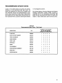
RECOMMENDED SPARE PARTS
67
DIAG RAMS
69
APPEN DIX . . . . . . . . . . . . . . • . . . . . . . . . . . . . . . . . . . . . . . . . . . . . . . . . . . .. 83
QUMETRAK842DC UNIQUE DATA
83
me
iv
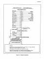
LIST OF ILLUSTRATIONS
FIG.
TITLE
1
2
3
4
5
6
7
8
9
10
11
12
13
14
15
16
17
18
19
20
21
22
23
24
25
26
27
28
29
30
31
32
33
34
35
36
37
38
39
40
41
42
43
44
45
46
47
48
49
50
51
52
Recommended Controller Interface Circuits
o. 3
Track Access Timing .
4
Read Timing ..
o.
4
Write Timing
5
Step Timing. . . . . . . . . . . . . . . . . . . . . . . . . . . . . . . . . . . . . . . . . . . . .. 5
Write Data Timing for Frequency Modulation (FM) .
5
Write Data Timing for Modified Frequency Modulation (MFM) ... 5
Index Timing .
5
Read Data Timing for Frequency Modulation (FM)
6
Interface Connection
;
, . . . . . . . . . . . . . . . . . .. 7
Interface Connection . . . . . . . . . . . . . . . . . . . . . . . . . . . . . . . . . . . . .. 8
J1 Connector Dimensions (component side)
8
Unpacking the Disk Drive
10
QuemTrak 842, Top View . . . . . . . . . . . . . . . . . . . . . . . . . . . . . . . . .. 11
QumeTrak 842, Side View
11
Disk Drive Mounting. . . . . . . . . . . . . . . . . . . . . . . . . . . . . . . . . . . . .. 12
PCB Jumper Locations, Test Points & Connector Pin Assignments
14
Disk Change Timing
18
Bail Gap Oheck
23
Head Load Time Check
,........................... 24
Azimuth Check
27
Drive Pulley Installation
28
BaH Assembly Removal and Replacement .....
o. 29
Bail Assembly Re..lnstallation
30
Drive Motor Assembly Removal and Replacement ..
30
Connector Lead Removal (typical)
30
In Use LED Removal and Replacement
30
Index Sensor Assembly Replacement
33
Carrier Assembly Removal and Replacement
34
Door Lock Solenoid Removal and Replacement. . . . . . . . . . . . . .. 36
Head Load Solenoid Removal and Replacement
38
Dust Cover Removal and Replacement
o. . .• 38
Head/Carriage Assembly Belt Clamp Access
o. 39
Steel Belt End Clamp Access
:
39
Steel Belt/Stepper Mechanism . . . . . . . . . . . . . . . . . . . . . . . . . . . .. 40
Steel Belt and Head/Carriage Alignment
41
Carrier..Collet Assembly Adjustment .. . . . . . . . . . . . . . . . . . . . . .. 44
Pop..Up Adjustment. . . . . . . . . . . . . . . . . . . . . . . . . . . . . . . . . . . . . .. 45
Bail Gap Adjustment
46
R/W Head Gap Adjustment
47
Index Lamp Assembly Positioning
47
Stepper Motor Pulley Track 40 Alignment
. . . . . . . . . . . . .. 48
R/W Head Radial Alignment
49
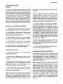
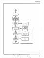
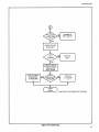
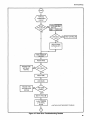
Power Failure Troubleshooting Flow Chart
o. 53
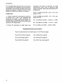
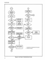
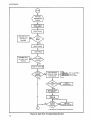
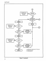
Not Ready Troubleshooting Flow Chart. . . . . . . . . . . . . . . . . . . . .. 54
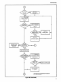
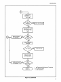
Seek Error Troubleshooting Flow Chart
56
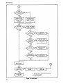
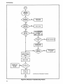
Read"Error TroubleshootJng Flow Chart.
59
Write Error Troubleshooting Flow Chart 0.................... 62
No Head Loads Troubleshooting Flow Chart ...
65
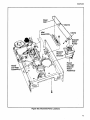
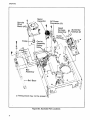
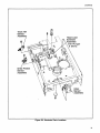
Illustrated Parts Locations, sheets a-f
70
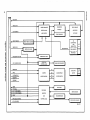
QumeTrak 842 Block Diagram
r 76
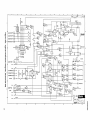
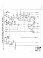
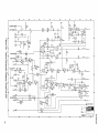
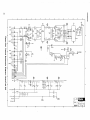
Typical Schematic Diagram, QumeTrak 842, sheets a-f
77
PAGE
0
0
0
0
0
0.00
•
0
0
0
•
0
••••
0
•
0
••••
0
0
0
••••••••
•••••
0
•••••••••••••••••••••••
••••••••••••••••••••••••••••••••
0
0
0
0
•
0
•••
0
•
0"
•••
••••••••
••
0
••
0
0
0
0
0
•
•
•
•
••
0
•
•
•
•
•
••
0
0
•
0
0
•
0
••••••••
0
0
••••••
:
•••••••••••••
0 • • • • • • • • • • • • • •
0
0
•
•
•
•
•
•
•
•
•
•
0
•
•
•
•
•
•
•
•
••••••••
•
0
•
•
0
•••
•
•
•
•
•
•
•
•
•
••
•
•
•
•
••
0
0
•
•
0
•••••
•
•
•
0
0
••
•
•
0
•
•
•
•
•
••
0
•
•
•
•
••
0
••
0
0
••••••••
0
•
0
0
•
•
•
0
•••••
0
0
••
•
•
•
•
•
0
•••
•
•
•
•
•
•
0
0
•••••••
0
•
•
••
0
••
0
•
•
•
o
••
0
•
0
0
••
•
••••••••
0
0
0
•
•
•
•
•
•
•
•
••
0
•••
0
0
•••••••••••••
•
•
•
•
•
•
•
•
•
•
•
•
0
••
0
0
0
v
LIST OF TABLES
TABLE
1
2
3
4
5
6
7
8
9
10
11
12
13
14
15
16
17
18
19
20
21
vi
Performance Specifications
Reliability and Maintenance
Drive Selection
I/O Signal Connector P1/J1 Pin Assignments
I/O Signal Connector P1 Requirements for Flat Cable
I/O Signal Connector P1 Requirements for Twisted Wire Pairs
DC Connector P5/J5 Pin Assignments
DC Connector P5/J5 Requirements
AC Connector PO/JO Pin Assignments
AC Connector PO/JO Requirements
Installation Requirements
Factorty Configuration of the Option Traces
Programmable Shunt Trace Functions
Mutiplexed Drive Select Options
Side Select Options
Maintenance Tools
Transducer Connector P2/J2 Pin Assignments
Head Connector P3/J3 Pin Assignments
Test Points
Recommended Spare Parts, Field Level
Recommended Spare Parts, Depot Level
PAGE
1
2
3
8
9
9
9
9
9
9
12
13
15
16
17
19
20
20
20
67
68
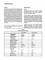
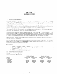
INTRODUCTION
SCOPE
DESCRIPTION
This manual contains information describing the
operation and maintenance of the QumeTrak 842
family of Flexible Disk Drives. This first section of
the manual describes the design features and
specifications. The INTERFACE section lists the
physical interface connections of the QumeTrak
842's and describes the electrical interface lines.
INSTALLATION provides inspection, unpacking,
mounting, and warranty and servicing information. CUSTOMER STRAPPABLE OPTIONS describes the available customer strappable options
and possible configuration modifications. MAINTENANCE provides preventive maintenance information, removal and replacement procedures,
adjustment instructions, and troubleshooting
procedures.
r--------- N O T E - - - - - - - - .
In this manual the meaia will be referred to
as simply a disk.
General
The QumeTrak 842's are low cost direct access
data storage devices that utilize a standard
removable eight-inch flexible IBM diskette or
equivalent as storage medium.
They are capable of supporting either IBM 3740
single density format (FM), or IBM System 34 double density format (MFM), including double sided
recording. The functional electrical and mechanical requirements of the interface conform to ANSI
(American National Standards Institute) standard.
They also provide both electrical and physical
interface compatibility with the Shugart SA850
Disk Drive.
QumeTrak 842's have a two-sided head/carriage
assembly containing two proven, ceramic
read/wrUe (R/W) heads, and a flexured mounting
arrangement that results in extremely high reliability. Fast access time (3 ms track to track) Is
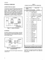
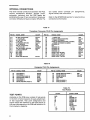
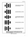
Table 1
Perform·ance Specifications
SINGLE DENSITY
DOUBLE DENSITY
0.8M bytes
0.6M bytes
1.6M bytes
1.2M bytes
3408 BPI
6816 BPI
48TPI
48TPI
NUMBER OF CYLINDERS
77
77
NUMBER OF TRACKS
154
154
FM
MFM
ROTATIONAL SPEED
360 RPM
360 RPM
TRANSFER RATE
250K bits/sec
500K bits/sec
LATENCY (AVERAGE)
83 ms
83 ms
AVERAGE
91 rns
91 ms
TRACK-TO-TRACK
3ms
3ms
SETTLING
15 ms
15 ms
HEAD LOAD TIME
35 ms
35 ms
MOTOR START TIME
2 sec
2 sec
CAPACITY PER DISK
UNFORMATTED
IBM FORMAT
RECORDING DENSITY
(TRACK NO. 76)
TRACK DENSITY
RECORDING METHOD
..
ACCESS TIME
INTRODUCTION
time (3ms track to track) is accomplished by a
pr,ecision steel belt drive mechanism that affords
minimal wear with low power dissipation.
The QumeTrak 842's weigh only 13 pounds (six kg)
and two drives can be mounted horizontally, or
three drives vertically in a standard 19-inch rack or
panel unit. Refer to the section on INSTALLATION
for additional installation requirements.
Standard features on the QumeTrak 842 include:
•
•
•
•
•
Negative DC power supply not required
Daisy chain capability for up to four disk
drives
ISO write protect circuitry
Program-controlled door lock that prevents
removal of the disk when the R/W heads are
loaded or in use
In Use LED activity indicator on the front panel
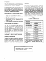
TRAINING
Qume offers two types of customer training on
the QumeTrak 842 Disk Drives; regularly scheduled classes held at Qume facilities and custom
on-site training held at the customer's facility. All
classes cover mechanical and electronic theory
of operation; field and depot service level troubleshooting; subassembly removal and replacement
procedures; mechanical and electronic adjustments; . service checks; and preventive maintenance. Detailed information on customer training
classes is contained in Memory Products Service
and Spares Catalog publication number 37032.
Table 2
Reliability and Maintenance
ERROR RATE
RECOVERABLE READ
ERROR RATE
ONE ERROR PER 109
BITS READ
This disk drive provides a storage capacity of
0.6M bytes on a two-sided single density flexible
disk (IBM DISKETIE 2 or equivalent), and 1.2M
bytes on the two-sided double density flexible
disk (IBM· DISKETIE 2D or equivalent). Refer to
the table above for additional performance
specifications. The next table lists the reliability
specifications.
NON·RECOVERABLE
READ ERROR RATE
ONE ERROR PER 1012
BITS READ
SEEK ERROR RATE
ONE ERROR PER 106
SEEKS
MTBF
8500 HOURS AT 100%
DUTY CYCLE
13000 HOURS AT 50%
DUTY CYCLE
MTTR
30 MINUTES
WARRANTY, SERVICE AND TRAINING
PREVENTIVE
MAINTENANCE
6,000 POWER ON HOURS
OR 2 YEARS
DESIGN LIFE
15,000 POWER ON HOURS
OR 5 YEARS
*MEDIA LIFE
3.5 x 10⁶
PASSES/TRACK
SPECIFICATIONS AND RELIABILITY.
WARRANTY AND SERVICE
The basic Qume service policy, terms, conditions
and prices for repairs are specifically described in
Memory Products Service and Spares Catalog,
publication number 37032. For specific warranty
details refer to your QumeTrak 842 purchase
contract.
*USEFUL MEDIA LIFE IS EXCEEDED WHEN "HEAD
OUTPUT" DROPS TO BELOW 80% OF INITIAL VALUE,
AS MEASURED BY USING IBM DISKETTE (IBM PIN
1766872).
...-------CAUTION - - - - - - - .
Never leave a drive in a motor-on condition
with a disk partially installed.
2
INTERFACE
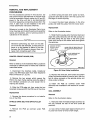
ELECTRICAL INTERFACE
GENERAL
The QumeTrak 842 has three interface connectors. Conector P1/J1 interfaces digital 110 signals.
Connector P5/J5 interfaces the +5 V and +24 V
DC power sources. The third connector (PO/JO)
interfaces the AC power source. The pin assignments for these connectors are identified in the
Interface Connections illustration below.
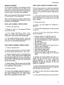
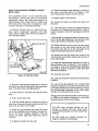
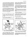
1/0 SIGNAL INTERFACE
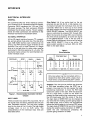
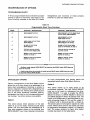
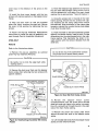
All the 1/0 signal interface lines are TTL compatible, and are active (true) when low. The disk drive
uses 7438 NAN 0 buffers (open collector) as line
drivers, and 7414 Schmitt trigger inverters as line
receivers. The input of each receiver in a single
drive or in the last drive of a daisy chain must be
terminated in 150 ohms pulled up to + 5 volts. The
illustration below shows the recommended controller interface circuit.
Drive Select 1·4. A low active level on the appropriate line (pin 26, 28, 30, or 32) enables communication between the individual drive and the
controller. When two or more (up to four) drives
are daisy chained, each drive must have a unique
DRIVE SELECT address. The DRIVE SELECT address is controlled by jumpers DS1 through DS4.
When the two pins of jumper DS1 are connected,
the drive will be activated by an active low signal
on the DRIVE SELECT 1 line. If the two pins of
jumper DS2 are connected, the drive will be active
when DRIVE SELECT 2 line is low active. The
same system applies to jumpers DS3 and DS4.
Refer to the table below.
Table 3
Drive Selection
Traces
Drive Select Input
I I DRIVE 1 I I DRIVE 2
CONTROLLER
_ _ _--.:.-1 t
SI
("',
'·1
I I
I I
I I
I I
I
I
7414
II II
TTL
I
7438 or eqUiValent;'
+5 V
1/4 w
I I
I I
74;~r ~uw.,.ntl
I
DRIVE 4
I
'I
I I
I I
I
-
I
1 1
10 Feet Max.
3
4
1
2
3
4
L
H
H
H
H
L
H
H
H
H
L
H
H
H
H
L
L
DS1 DS2 DS3 DS4
S
0
0
0
0
S
0
0
0
0
S
0
0
0
0
S
= low level, H = high level, S = short, 0 = open
7414
TTL
TTL
I I
7438 I
2
+5 V
I
I I
1
I
trdttJiG
1 1
I.
J
I
I r-I-'-_~f-~
1-< I
D
'I
Drive
Number
7438 1
I
,I
..I
7438
..
Figure 1. Recommended Controller Interface
Circuits
INPUT LINES
There are twelve low active TTL input lines. Ten of
the signal lines are factory standard and two are
user installable options. The low (true) voltage
level for the lines is 0 to 0.4 volts. The high (false)
voltage level is 2.4 to 5.25 volts. The
characteristics of the individual input lines are
described below.
.....- - - - - - - N O T E - - - - - - - Only one jumper can be connected within a
single drive. Each drive within a daisy chain
must have a unique DRIVE SELECT number.
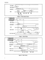
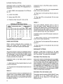
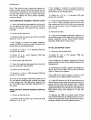
Direction. This line (pin 34) defines the direction
of R/W head movement when the STEP line is
pulsed. A low level on this line causes the head
positioning mechanism to move the R/W head
toward the center of the disk. With the Direction
line at a high level, a pulse on the STEP line
causes the head positioning mechanism to move
the R/W head away from the center of the disk.
The logic state of DIRECTION can be changed at
any time after the trailing (positive going) edge of
the STEP pulse, and to within one microsecond
before the trailing edge of a following STEP pulse.
The logic state of DIRECTION cannot be changed
during the positive going transition of STEP, or
within the one microsecond preceding the
positive going transition of STEP.
3
INTERFACE
--------4;< Sr------....----
--1,...-----~f~s
--I
DC POWER
f--
':I~
I_~I
,
DRIVE SELECT
t--
---i
DIRECTION
0.5 ~. min.
~
f\
f
~,.....
' -------
STEP
Figure 2. Track Access Timing
AC MOTOR POWER
(QUMETRAK 842)
DC MOTOR POWER
(QUMETRAK 842DC)
DC POWER
DRIVE SELECT
---.J
r-=
2 ••e min.
---1
"'1- - - - - - . ; . . - - - - - - - - - - - - - - -
---h
-j
.
-----1-----------
SOf-lo.-mln- .
S~:pSELECT --~Im-·I~---__i~llo..,;r-10-0-1'.-m-ln.-------"
I
WRITE GATE
--tJ--:
,
'i
--i
II
W- ~3:'~~~ H~~~
EI
VALID READ DATA
L---l
El
r'
590
~. min.
~ ~" .. ,,~n
~
Figure 3. Read Timing
AC MOTOR POWER
(QUMETRAK 842)
DC MOTOR POWER
.--J
fo4--
~UM~~KMmQ
I
DC POWER
2 ••
'
IL..-DRIVE SELECT
SIDE SELECT
emin.
--I
·I------~~~---------~---~
90
ml min. -
-
1
I~ 590 ~. min.
-----II----7-------:----:--------~1
---f 35 m. min. I--I'-- 590 ~. min.
I
II
,,..------,,;,.,,------1 1---- 100 min.
I
1
1"
STEP
WRITE GATE
WRITE DATA
----1t:,Lmm.
Figure 4. Write Timing
4
i
l-:::.:.:.-_-_-_-_-_-_-_~_
-----,
i
---.lI----
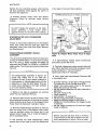
INTERFACE
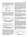
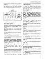
Step. The negative going edge of the STEP pulse
on this line (pin 36) will cause the R/W head to be
moved one track. The direction of movement is
controlled by the DIRECTION line. The pulses applied to the STEP line have the timing
characteristics shown below.
*ml·· V __
1
#oil
Side Select. SIDE SELECT (pin 14) defines which
surface of a two sided media disk is used for data
recording or retrieval. A low active level on this
line selects the R/W head for surface 1 (the disk
side facing the carrier assembly). A high level on
this line selects the R/W head for surface 0 (the
disk side facing the PCB). When switching from
side 0 to side 1 and conversely, a 100 microseconds delay is required before any read or write
operation can be initiated. Refer to the section on
CUSTOM ER STRAPPABLE OPTIONS for alternate
methods of head selection.
min.
Figure 5. Step Timing
Write Data. On this input line (pin 38) arrives the
data to be written on the disk. Each transition
from a high level to a low active level on this line
causes the write current through the head to be
reversed. The WRITE DATA timing characteristics
for Frequency Modulation (FM) and Modified Frequency Modulation (MFM) formats are shown
below.
Low Current. A low active level on this line (pin 2)
is required for writing on tracks 44 through 76.
This input is used to lower the write current by
20 % , consequently improving the read output
resolution of the inner tracks.
·Head Load. A low active level on this optional input (p~n 18), when the drive's internal READY
status is active, causes the R/W heads to be loaded against the disk. Refer to the section on
CUSTOMER STRAPPABLE OPTIONS for uses and
method of installation of this line.
In Use. A low active level on this optional input
(pin 16) will energize the In Use LED. Refer to the
section on CUSTOMER STRAPPABLE OPTIONS
for uses and method of installation of this line.
OUTPUT LIN ES
Figure 6. Write Data Timing for
Frequency Modulation (FM)
Figure 7. Write Data Timing for Modified
Frequency Modulation (MFM)
Write Gate. A low active level on this line (pin 40)
enables the w~ite current source, and disables the
stepping (head movement) circuitry. A high level
on this line enables the read circuitry. Deactivation of DRIVE SELECT, and/or changing SIDE
SELECT must be delayed at least 590
microseconds following a write operation to
assure that the track is fully tunnel erased. The
READ TIMING and WRITE TIMING diagrams illustrate the timing relationships.
There are seven output lines from the QumeTrak
842, five of wh ich are factory standard and two
may be user activated upon option. The low (true)
voltage level for the lines is 0 to 0.4 volt. Maximum
output circuit sink capability is 48 milliamps. The
high (false) voltage level is 2.4 to 5.25 volts, with a
maximum collector cutoff leakage current of 250
milliamps. The characteristics of the individual
output lines are described below.
Index. This interface signal (pin 20) is provided by
the drive once each disk revolution. The leading
(negative going) edge of each INDEX pulse indicates to the controller the beginning of a track.
The timing characteristics for INDEX are shown
below.
Figure 8. Index Timing
5
INTERFACE
Ready. A low active level on this line (pin 22) indicates that at least three index pulses have been
s,ensed (two completed revolutions by a properly
inserted disk with the drive door closed). READY
will go true only if the proper side (0) is selected
when a one-sided disk is used. Refer to the section on CUSTOMER STRAPPABLE OPTIONS for
alternate use of READY.
Track 00. A low active level on this line (pin 42) indiicates that the RIW head is positioned at
Track 00.
Write Protect. A low active level on this line (pin
44) indicates that a disk with an ISO write protect
notch is loaded. Under normal operation, the drive
will inhibit writing when a protected disk is installed. Refer to the section on CUSTOM ER STRAPPABLE OPTIONS for alternate operation.
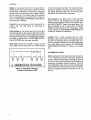
Read Data. Data from the disk is output to the
host system in the same form as it was received
l
Disk Change. A low active level on this optional
output line (pin 12) indicates that the disk drive
door has been opened and the disk ejected after
the DRIVE SELECT signal has gone false. The
DISK CHANGE circuit is reset after the DRIVE
SELECT signal goes true then false again. Refer
to the section on CUSTOMER STRAPPABLE OPTIONS for method of installation.
2-Sided. With a disk installed and the drive
selected, a low active level on this optional output
line (pin 10) indicates that a two-sided disk is in
use. A high level indicates that a single-sided disk
is in use. Refer to the section on CUSTOM ER
STRAPPABLE OPTIONS for method of installation.
ALTERNATE 1/0 PINS,
I
i
c
C=
0=
o
c
Leading Edge of Bit Can Be
Leading Edge of Bit Can Be
c
:I: 350
:I: 175
o
c
ns From Nominal.
ns From Nominal.
Figure 9. Read Data Timing for
Frequency Modul'ation (FM)
6
on the write data line. Each flux reversal that is
sensed on the disk produces a low active pulse on
the READ DATA line (pin 46). The timing characteristics for READ DATA are shown.
Eight alternate I/O pins are provided on connector
J1 for interfacing the disk drive with additional
control signals. These eight alternate 1/0 pins (4,
6,8,10, 12, 16, t8, and 24) connect to PCB pads for
customer install able optional jumpers. Two factory designated input and two factory designated
output lines of the drive internal circuits are selectable by installing jumpers to 1/0 pins 10, 12, 16,
and 18.
INTERFACE
FROM CONTROLLER. '_ _
F_RO
__
M_Q_U_M_E_T_R_A_K_8_4_2_ _
SIGNAL CONNECTOR (P1/J1)
SIDE SELECT
14 ...
IN USE •
16 _
HEAD LOAD •
18 _
-
- ---
10
2-SIDED *
_12
DISK CHANGE *
20
INDEX
22
READY
_42
TRACK 00
2 _
LOW CURRENT
DRIVE SELECT 1
26 •
DRIVE SELECT 2
28 •
DRIVE SELECT 3
30 _
DRIVE SELECT 4
32 _
DIRECTION
34 _
STEP'
36 _
WRITE DATA
38 _
WRITE GATE'
40 _
--
--
- ---
_ 44
WRITE PROTECT
46
READ DATA
.
-
--
--
SIGNAL' RETURNS
4.6, 8, 10,12, 16, 18, 24
ALTERNATE I/O
-...
DC POWER CONNECTOR (P5/JS)
+24 VDC
1
24 V RETURN
+5 VDC
5
5 V RETURN
1
2
6
...
-----
AC/DC MOTOR POWER CONNECTOR (PO/JO)
AC INPUT (aUMETRAK 842)
+24VDC (aUMETRAK 842DC) 1 _
FRAMEGROUND (aUMETRAK 842)+24V RETURN aUMETRAK 842DC)
2
In
ACINPUT (aUMETRAK 842) 3
--
, - - - - - - - - - - - - - - - - - - - NOTES: - - - - - - - - - - - - - - - - - - - - .
1. * Optional.
2. Signal returns (all odd numbered pins on P1/J1), + 24 V return, + 5 V return, and frame
ground must be connected together at the controller.
3. Pins 48 and 50 on P1/J1 and Pins 3 and 4 on P5/J5 are reserved.
4. Signal names "SIDE SELECT" and "2-SIDED" have been changed (from "HEAD
SELECT" and "DISK 2 SENSE", resp.) to comply with ANSI specifications.
Figure 10. Interface Connections
7
INTERFACE
PHYSICAL INTERFACE
Table 4
I/O Signal Connector P1/J1 Pin Assignments
CONNECTORS AND CABLES
The physical interface between the QumeTrak 842
and the host system is made through three connectors, digital 110 signals (P1/J1), DC power
(P5/J5), and AC power (PO/JO). The illustration
below shows how four disk drives would be connected to the host system (drives #2 and #3 have
been deleted for clarity). Refer to ELECTRICAL
INTERFACE for specific I/O signal discussion.
SIGNAL
RETURN
SIGNAL
PIN NO.
PIN NO. STANDARD
QUMETRAK
rt1
AC POWER
t---\-:'------------T • TERMINATOR (LAST
DRIVE IN CHAIN ONLY)
Figure 11. Interface Connection
110 SIGNALS
I/O signal interfacing occurs through connection
P1/J1 in the form of a 50-pin PCB edge connector.
The dimensions for this connector are shown in
the illustration below.
50
BCMrd Thlckn...
.01l2:!: .007
.450:!: .010
1
OPTION
3,5,7
4,6,8
ALTERNATE I/O
1
2
LOW CURRENT
9
10
ALTERNATE I/O
TWO-SIDED
11
12
ALTERNATE I/O
DISK CHANGE
13
14
SIDE SELECT
I/O
ALTERNATE
I/O
15
16
ALTERNATE I/O
IN USE
17
18
ALTERNATE I/O
HEAD LOAD
19
20
INDEX
21
22
READY
23
24
ALTERNATE I/O
25
26
DRIVE SELECT 1
27
28
DRIVE SELECT 2
29
30
DRIVE SELECT 3
31
32
DRIVE SELECT 4
33
34
DIRECTION
35
36
STEP
37
38
WRITE DATA
39
40
WRITE GATE
41
42
TRACK 00
43
44
WRITE PROTECT
45
46
READ DATA
47
48
RESERVED
49
50
RESERVED
I/O SIGNALS
HOST
SYSTEM
SIGNAL NAME
NOTE
Also check Factory Configuration of Option Traces and
Program Shunt Trace Functions table when interfacing.
Figure 12. J1 Connector Dimensions
(Component Side)
The table below lists the I/O signal connector pin
assignments.
8
Connector P1 can be for flat cable or twisted wire
pairs. The two tables below list the respective
requirements.
INTERFACE
Table 5
1/0 Signal Connector P1 Requirements
for Flat Cable
PARTS
3M PIN
CONNECTOR
3415·0001
POLARIZING KEY
3439·0000
P5
(CABLE SIDE)
J5
(DRIVE SIDE)
PARTS
AMP PIN
AMP PIN
HOUSING
1·480270·0
1·380999·0
CONTACT (6 PINS)
60619·1
CRIMP TOOL
90124·2
EXTRACTOR TOOL
1·305183·2
-
CABLE (10 FEET
MAX.)
AWG 18 OR 16
-
3440
PRESS
CRIMP
TOOL
Table 8
DC Connector P5/J5 Requirements
LOCATOR PLATE
3443·11
PLATEN
3442·1
FLAT CABLE (10 FEET
MAX.)
3365·50
Table 6
1/0 Signal Connector P1 Requirements
for Twisted Wire Pairs
CRIMP
TYPE
SOLDER TYPE
PARTS
AMP PIN
AMP PIN
VIKING PIN
HOUSING
1·583717·1
1·583717·1
3VH25/1JN·5
CONTACT
583616·5
583854·3
-
POLARIZING KEY 583274·1
583274·1
091·0071·000
CRIMP TOOL
90268·1
-
-
EXTRACTOR
TOOL
91073·1
91073·1
-
TWISTED PAIRS
(20 FEET MAX.)
AWG 26
AWG 26
AWG 26
-
AC POWER
AC power is interfaced through connector PO/JOe
The two tables below list the connector pin
assignments and the cable requirements.
Table 9
AC Connector PO/JO Pin Assignments
PIN NO.
SIGNAL NAME
1
AC IN.PUT
2
FRAME GROUND
3
AC INPUT (NEUTRAL)
Table 10
AC Connector PO/JO Requirements
DC POWER
PO
(CABLE SIDE)
JO
(DRIVE SIDE)
PARTS
AMP PIN
AMP PIN
HOUSING
1·480700·0
1·480701·0
CONTACT (3 PINS)
350550·1
350705·1 AND
350669·1
CRIMP TOOL
90296·1
90296·1
SIGNAL NAME
EXTRACTOR TOOL
458994·1
458994·1
1
+24 VDC
CABLE (20 FEET MAX.)
AWG18 OR 16
AWG 18 OR 16
2
+ 24 V RETURN (GND)
3
NOT USED (GND)
4
NOT USED
5
+5 VDC
6
+ 5 V RETURN (GND)
DC power is interfaced through connector P5/J5.
The two tables below list the connector pin
assignments and the cable requirements.
Table 7
DC Connector P5/J5 Pin Assignments
PIN NO.
TERMINATORS
Input line terminators in the form of two DIP
resistor modules must be plugged into DIP
sockets on the PCB of a single drive or of the last
drive only in a daisy chain.
9
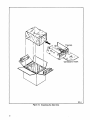
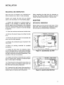
Cardboard Insert
381·A
Figure 13. Unpacking the Disk Drive
.
10
INSTALLATION
RECEIVING AND INSPECTION
Each disk drive is shipped in an individual con·
tainer protected by a layer of foam packaging.
Unpack and inspect the disk drive as follows
(refer to the illustration on the preceding page):
1. Inspect the container for external signs of
damage. If any damage is observed, have the
delivery agent note the damage on the shipping
document. Some shippers may wish to be present
when the container is opened if external damage
is apparent.
When repacking the disk drive for shipping or
storage, use original packing material only and
follow the above instructions in reverse order.
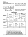
MOUNTING
MECHANICAL DIMENSIONS
Shown below are the top and side views of the
disk drive. The mounting and clearance dimen·
sions should be reviewed before installation.
2. Open the container and remove the disk drive.
3. Remove the plastic bag surrounding the disk
drive.
4. Remove the piece of foam from between the
carrier and the <bail assembly.
5. Remove the cardboard square inserted in the
front panel.
6. Retain all packing materials for possible
reshipment.
7. Inspect the disk drive for scratches, dents,
loose or damaged parts, or other signs of damage.
Note any evidence of such damage on the invoice,
and file a claim with the carrier immediately, if the
condition of the unit so warrants.
14.57: .08
Figure 14. QumeTrak 842, Top View
8. Inspect the interior of the entire unit. Look for
loose or broken parts, evidence of electrical dam·
age, or other signs of damage.
9. If the drive will not be used for some time, it is
advisable to place the cardboard insert back into
the drive after completing inspection.
10. If damage that might impair drive operation is
detected, do not attempt to operate the disk drive.
Contact Qume for advice and instructions.
~
1 J
.40:.06-1
.80: .04-1 1--4.00: .02
4.00: .02
Dimensions
in inches
Figure 15. QumeTrak 842, Side View
11
INSTALLATION
RECOMMENDATIONS
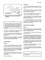
The QumeTrak 842 can be mounted in any plane;
horizontally for front loading, vertically for front
loading, or vertically for top loading. However,
when the disk drive is mounted in a horizontal
front-loading position it must be oriented such
that the In Use LED indicator on the front beze1 is
below the front door as shown in the illustration.
INSTALLATION REQUIREMENTS
Improperly Installed
(PCB up)
Properly Installed
(PCB down)
Figure 16. Disk Drive MountiRg
The QumeTrak 842 has certain power, environmental, and mechanical requirements. Review the
table below before installing the disk drive.
Table 11
Installation Requirements
VOLTS
CURRENT
100/115 VAC
INSTALLATIONS
100/115 VAC ± 10%
50/60 HZ ± 1%
0.8 A MAX. (START UP)
0.4 A MAX. (RUNNING)
200/230 VAC
INSTALLATIONS
200/230 VAC ± 10%
50160 HZ ± 1%
0.6 A MAX. (START UP)
0.3 A MAX. (RUNNING)
AC POWER
REQUIREMENTS*
VOLTAGE
MAX. RIPPLE
CURRENT (AMPS)
1 DRIVE
DC POWER
REQUIREMENTS**
POWER
DISSIPATION
3 DRIVES
4 DRIVES
+24 V
± 10%
0.1 V (P·P)
TYP.
MAX.
0.7
1.0
0.8
1.2
0.9
1.4
1.0
1.6
+5V
±5%
0.05 V (P·P)
TYP.
MAX.
0.9
1.3
1.6
2.2
2.3
3.1
3.0
4.0
55 W (190 BTU/HR) MAX.
ENVIRONMENTAL
MECHANICAL
2 DRIVES
OPERATING
STORAGE
TEMPERATURE
+ 5°C TO + 43°C
(41°F TO 110°F)
·10°C TO + 45°C
(14°F TO 113°F)
RELATIVE
HUMIDITY
20 TO 80%
8 TO 80%
MAX. WET BULB
+ 29°C (84 ° F)
NO CONDENSATION
REFER TO PARAGRAPH ON MOUNTING
NOTES:
1. *Not applicable to the QumeTrak 842DC disk drive.
2. **Referto the APPENDIX for QumeTrak 842DC disk drive power requirements.
3. DC power voltage as specified Is at the DC power connector (J5) on the PCB.
4. DC supply current is for drives that are normally Installed without customer options.
5. If the stepper motor and door solenoid are energized on all drives continuously, the maxi·
mum current requirement for the + 24 V supply is 1.0 A times the number of drives on the daisy
chain.
12
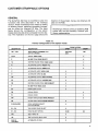
CUSTOMER STRAPPABLE OPTIONS
GENERAL
. The QumeTrak 842 may be modified to alter the
functions that were described in the Interface
section. These modifications are made by adding
or deleting traces, installing pluggable jumpers,
and by usIng the Alternate I/O pins. The table
below shows the configuration of the option
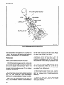
traces when the disk drive is shipped from the factory. The illustration on the next page shows the
location of the jumpers, traces, and Alternate 1/0
pads on the PCB.
. . . - - - - - - - C A U T I O N - - - - - -......
Modifying a drive by cutting or soldering PCB
traces may void the warranty. Consult your
Qume representative.
Table 12
Factory Configuration of the Option Traces
FROM FACTORY
DESIGNATOR
DESCRIPTION
OPEN
SHORT
DS1 - DS4
DRIVE SELECT ADDRESS PINS
(UP TO 4 DRIVES)
DS2,DS3
DS4
DS1
A,B,X
RADIAL HEAD LOAD
X
Z
IN USE FROM DRIVE SELECT
X
HL
STEPPER POWER FROM HEAD LOAD
X
R
ALTERNATE OUTPUT READY PAD
X
I
ALTERNATE OUTPUT INDEX PAD
X
C
ALTERNATE INPUT HEAD LOAD
X
D
ALTERNATE INPUT IN USE
X
DC
ALTERNATE OUTPUT DISK CHANGE
X
2S
ALTERNATE OUTPUT 2-SIOED DISK
X
OS
STEPPER POWER FROM DRIVE SELECT
X
y
IN USE FROM HEAD LOAD
X
DL
DOOR LOCK LATCH
X
RR
RADIAL READY
X
RI
RADIAL INDEX
X
WP
INHIBIT WRITE WHEN WRITE PROTECT
X
NP
ALLOW WRITE WHEN WRITE PROTECT
X
D1,D2,04,DOS
DRIVE ADDRESS SELECT
(UP TO 8 DRIVES)
X
B1 - 84
TWO-SIDED DRIVE SELECT
X
S1 - S3
HEAD SELECT OPTION
S1,S3
T40
TEST TRACK 40
X
HA
TEST ACTUATE HEAD LOAD
X
4,6,8,10,
12,16,18,24
ALTERNATE I/O PINS
X
52
13
CUSTOMER STRAPPABlE OPTIONS
1
o
11-..
1".,.,..,.,.,"'7r11'
~ ~ ~
•
vorive Select
'
"
•
'i:• .
••
S1::
_ _....2 _ L
-1.L~
....
It~
Optional
Alternate _ _~10...,-..2S :
I/O Pins
B
B
!
DC.
~~
TM2
~«
1
A611
A7.
B8.
!l!i
~ ~:;;:~Nt ~ ,%: i~~5
~
)!@§]
~
® -r:==k~C30
~
z
,
r:
T
OL OS GNO
1/
")(,"*...
r:lN4
+
CA~u
Test Points
+
=
, AN3
Radial Ready, Index
~
~.
B
+
~ ~ Programmable Shunts
-+-
.~,
::E
CA26,....--,. . A1:
q~
1/0
1E!iHHm
a:
+
15
J 1 Interface Connector
. . -. . -.
"-·· .·. - .·~r
0
C51
q~
El
A
®®alf
+
N
Head Select
~~ ••~
--<:::)fB33~29 ~27
Z
C44
If
~35~A31 ~ 6 Transducer
~34~30~28Connector
014
i
0
C45
wli.
@)
au ME
DOS
~l~st~~b
O
VA8
. ~
-0--69
~36~32~7
.S01
02
•
04
...
WPNP
LC LS
_.
TM1
q~
v
Termlnatora
~:
~
CA24
Q=OOE= ~+~
~'O
tQ'6\
V~
~
P
CQI]+
CR17.
Write Protect
V~~
z
R16
rQ5\
y;::;
S
Test Points
X: :t/ e g~A~~~~~l\£0D- ~ li~?
~"~_sD-bh!ie@
51
C
L2
Connector
A56
:6~LJ:J51
013
-c:::::J-
"'N
4
CA21
53
CA20
:4:2c::J~1@11
.~b3:~~~~~~~~I~~!:::~~
~ £ ~ ~ ~ ~ ~ -:-I C18 ~
L ~..J
2
---c:::h:;;
o
§;:9 @J~~9 ~+ g:9 ~+ ~oo...U
Ll1
C24 A5rnJ2+
M
~
M'"
N
~
...
~
0
C 17
12
~3
R36
@
~
~
v @ ... tQ'2\
ill ~ ~26&~CA14
C~~
A4
-L.-.:2.-.J
~
C16
Q11
~
--ffiN}---{EID-
10
10
~ --EEID-
e
V
09
08 CA12
Qco@ 1 918
Q15
U
4JOC14
N
C11
-c=JA31
7
J3
1
~1R11
CA10
B:::tE3=
0
Head Connector
21
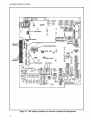
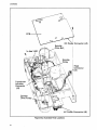
Figure 17. PCB Jumper Locations, Test Points & Connector Pin Assignments
14
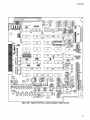
CUSTOMER STRAPPABLE OPTIONS
INCORPORATION OF OPTIONS
PROGRAMMABLE SHUNT
A 16-pin programmable shunt with seven jumpers
(shorts) in place for commonly used trace cut options is factory installed on the drive P.C. board.
Designations and functions of these jumpers
(shorted vs. open) are listed below.
Table 13
Programmable Shunt Trace Functions
TRACE
FUNCTION - SHORTED (STD.)
FUNCTION - OPEN (OPTION)
A
DRIVE SELECT ACTIVE
DRIVE SELECT ACTIVE, HEAD lOAD
ACTIVE FROM DRIVE SELECT
B
DRIVE SELECT ACTIVE
DRIVE SELECT ACTIVE
HEAD LOAD ACTIVE
X
HEAD LOAD ACTIVE FROM
DRIVE SELECT
HEAD LOAD ACTIVE FROM
DRIVE SELECT OR IN USE
Z
IN USE ACTIVE FROM
DRIVE SELECT
IN USE ACTIVE FROM HEAD
LOAD OR OPTIONAL IN USE 110
STEPPER MOTOR POWER
ACTIVE FROM HEAD LOAD
STEPPER MOTOR POWER IS
ALWAYS ACTIVE
R
READY IN MULTIPLEX MODE
(REFER TO NOTE 1)
READY tN RADIAL MODE
(REFER TO NOTE 2)
I
INDEX IN MULTIPLEX MODE
(REFER TO NOTE 1)
INDEX IN RADIAL MODE
(REFER TO NOTE 2)
HL
NOTES:
1. Multiplex mode requires DRIVE SELECT to check that the READY and/or INDEX lines are
active on any drive.
2. Radlal mode allows the controller to check that the READY and/or INDEX lines are active
on any drive without DRIVE SELECT.
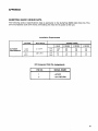
DRIVE SELECT OPTIONS
Factory configuration of the Drive Select circuit
allows for up to four drives to· be addressed in a
daisy chain arrangement. Normally, a jumper is
factory installed in location DS1, designating the
drive as number one. Moving this jumper to any
one of the three remaining locations (DS2-4),
designates the drive for the corresponding position number. Two other options are available
Option 1
This option allows direct selection of the disk
sides of up to two daisy chained double sided
drives. The four disk sides are addressed as if
they were separate drives on the existing four
DRIVE SELECT input lines. Detailed instructions
on input configuration and jumper status are
presented below under Side Select Options.
Option 2
This option allows up to eight drives to be
mUltiplexed together. The four DRIVE SELECT
lines are to be used for addressing the drive.
DRIVE SELECT 1 is used to enable the DRIVE
SELECT 2 (binary 1), DRIVE SELECT 3 (binary 2)
and DRIVE SELECT 4 (binary 4) address lines. The
logical drive assignment is accomplished by properly jumperlng traces D1, D2, and D4, where 01
(bina,ry 1), D2
(binary 2) and 04 = (binary 4).
The jumper pads are arranged to appear as a 3X3
matrix. Within each column, the center pad must
be jumpered to an adjacent Logical 1 or Logical 0
pad. The proper jumpers for each drive select
number are shown in the table below.
=
=
15
CUSTOMER STRAPPABLE OPTIONS
Installation (refer to the PCB Jumper Locations,
Test Points and Connector Pin Assignments illustration):
'1. Add a 74L85, 4-bit comparator IC in PCB location 1K.
Installation (refer to the PCB Jumper Locations
illustration):
1. Open traces Band HL on the programmable
shunt with a small screwdriver.
2. Plug trace C on the optional I/O pins near connector J1.
2. Jumper trace DDS.
3. Unplug trace 051-054.
3. Plug trace OS on the optional I/O pins near
connector J2.
4. Properly jumper traces 01, 02, and 04.
Option 3
..Table 14
Multiplexed Drive Select Options
DRIVE
'NUMBER
0
1
2
3
4
5
6
7
DRIVE SELECT INPUT
JUMPER CENTER
PAD TO:
1
2
3
4
01
02
04
L
L
L
L
L
L
L
L
H
H
H
H
H
L
L
H
H
L
L
H
H
L
L
L
L
0
1
0
1
0
1
0
1
0
0
1
1
0
0
1
1
0
0
0
0
1
1
1
1
L
H
L
H
L
H
L
L= LOW LEVEL, H = HIGH LEVEL
HEAD LOAD OPTIONS
This option (RADIAL READY) allows a drive to
load the heads without selecting the drive or
enabling the stepper motor. The advantage is that
the heads can be kept loaded on all the drives,
thereby eliminating the head load time when the
drive is performing a disk copy operation.
Installation (refer to the PCB Jumper Locations illustration):
1. Open traces A and HL on the programmable
shunt with a small screwdriver.
2. Plug trace G on the optional I/O pins near connector J1.
When a factory configured drive is selected, its
heads are loaded and the stepper motor is
energized. Three other options are available.
3. Pl'ug trace OS on the optional I/O pins near
connector J2.
Option 1
SIDE SELECT OPTIONS
This option allows a drive to be selected without
loading the heads or enabling the stepper motor.
The advantage is that the output status signals
can be monitored while the head is unloaded,
thereby extending the media life.
Normally, a R/W head is selected by the SIDE
SELECT interface line in a daisy chain system of
up to four drives. Two options are available:
Installation (refer to the PCB Jumper Locations
illustration):
11. Open trace X on the programmable shunt with
a small screwdriver.
2. Plug trace C on the optional I/O pins near connector J1.
Side Select From Direction Line
This option allows both SIDE SELECT and DIRECTION to be multiplexed on the same DIRECTION
line. By cutting trace S2 and jumperlng trace 51
near connector J1 (refer to the PCB Jumper Locations illustration), head selection is controlled by
the DIRECTION line. DIRECTION can be used in
this way because it is not being used during
reading or writing (STEP must accompany DIRECTION to initiate head movement).
Option 2
Side Select From Drive Select Lines
This option allows a drive to be selected and the
stepper motor to be enabled without loading the
heads. As an example of this option, initial reset
to Track 00 at power-on can be performed without
the READY condition.
, 16
This option uses the existing DRIVE SELECT lines
to address up to two double sided drives. It
selects up to four sides as if the sides were
separate drives.
CUSTOMER STRAPPABLE OPTIONS
Installation (refer to the PCB Jumper Locations illustration):
2. Open trace I on the programmable shunt with
a small screwdriver.
Cut trace 82 and jumper trace 83. The disk sides
are then selected according to the table below.
3. Jumper pad I (directly below the programmable shunt) to one of the available Alternate I/O
pins (4,6,8, or 24). INDEX will then appear on the
chosen Alternate 1/0 pin.
Table 15
Side Select Options
DRIVE
HEAD DRIVE SELECT INPUT
4
NUMBER SELECT
1
2
3
1
1
2
2
0
1
0
1
L
H
H
H
H
L
H
H
H
H
L
H
H
H
H
L
IN USE OPTIONS
TRACES
PLUG DS1
JUMPER 82
PLU~ DS3
JUMPER B4
Normally, the In Use LED indicator will be energized .while DRIVE SELECT is active. The door
solenoid will be activated when DRIVE SELECT
and READY are active. The three options listed
below will energize the In Use LED when activated
to a low level.
Option 1
L
= LOW LEVEL, H = HIGH LEVEL
This option will turn on the In Use LED when the
DRIVE SELECT or IN USE line is active.
RADIAL READY OPTION
Installation (refer to the PCB Jumper Locations illustration):
The READY line from a factory configured drive Is
only available to the interface when the drive is
selected.
Plug trace D on the optional I/O pins near connec·
tor J1.
This option enables the user to monitor the
READY line of each drive on the interface continuously.
Installation (refer to the PCB Jumper Locations
illustration):
Option 2
This option will energize the In Use LED when the
HEAD LOAD or IN USE line is active.
Installation (refer to the PCB Jumper Locations illustration):
1. Cut trace RR (near the center of PCB).
2. Open trace R on the programmable shunt with
a small screwdriver.
3. Jumper pad R (directly below the programmable shunt) to one of the available Alternate 1/0
pins (4,6,8, or 24). READY will then appear on the
chosen Alternate 110 pin.
1. Open trace Z on the programmable shunt with
a small screwdriver.
2. Plug trace D on the optional I/O pins near connector J1.
3. Plug trace Y on the optionalI/O pins near connector J2.
RADIAL INDEX OPTION
Option 3
The INDEX line from a factory configured drive is
only available to the interface when the drive Is
selected.
This option enables the user to monitor the INDEX
line of each drive on the interface continuously.
Installation (refer to the PCB Jumper Locations illustration):
1. Cut trace R1 (near the center of the PCB).
This option will energize the In Use LED only when
the IN USE line is active.
Installation (refer to the PCB Jumper Locations
illustration):
1. Open trace Z on the programmable shunt with
a small screwdriver.
2. Plug trace 0 on the optional 110 pins near con·
nector J1.
17
CUSTOMER STRAPPABLE OPTIONS
DOOR LOCK LATCH OPTION
With this option, the door lock actuator can be latched without maintaining the' IN USE signal
throughout the door lock Interval. IN USE may be
activated by D.RIVE SELECT.
Installation (refer to the PCB Jumper Locations
illustration):
Plug trace DC on the optional 110 pins near connector J1.
Installation (refer to the PCB Jumper Locations
ill ustration):
1. Plug trace D on the optional 110 pins near connector J1.
Fa'••
DRIVE SEL...
E-.CT_ _...
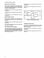
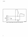
WRITE PROTECT OPTION
With this option installed, a Write Protected disk
will not inhibit writing but it will be reported to the
controller.
True
I
~no.:--_Tr_ue_.;--
L
Fa'..
READ__y
2. Plug trace DL on the optional 110 pins near
connector J2.
~
DISK CHANGE
I II
Fal..
------~-~
~
~TN'
_
.,
Door Open
Figure 18. Disk Change Timing
Installation (refer to the PCB Jumper Locations'
illustration):
2-SIDED (Alternate Output)
Cut trace WP and jumper trace NP (located near
the center of the PCB).
DISK CHANGE (Alternate Output)
A low active level on this option line indicates that
the disk drive door has been opened manually, the
disk removed after the DRIVE SELECT signal has
gone false, and then true again after a (different)
disk has been installed.
18
A low level on this line indicates that a two-sided
disk is in use; a high level indicates a single-sided disk being used.
Installation (refer to the PCB Jumper Locations
illustration):
Plug trace 2S on the optiof)al 110 pins near connector J1.
MAINTENANCE
PREVENTIVE MAINTENANCE
The QumeTrak 842 drive should be cleaned every
six months as outlined below. This interval
assumes a reasonably dust-free environement. In
use keep the disk drive as free from dirt as possible. Place the unit in a clean plastic bag or sealable box when not in use for prolonged periods.
A general service check should be performed on
the QumeTrak 842 every 6000 power-on hours.
Include in this check inspecting for loose components and connectors. Re-tighten loose screws
but be careful not to change the setting of adjustment screws, especially in the Head/Carriage
Assembly and the Carrier Assembly areas.
Inspect the Spindle Drive Belt (Qume P.N.
50025-01) and replace it if any evidence is found
of fraying, cracking, or otherwise weakened
areas. Perform the checks outlined under Service
Checks in this part of the manual. Periodic adjustments are not required under normal operating
conditions.
,.......------CAUTION------......
The head/carriage assembly is factory adjusted and tested and is not field serviceable. Do not, for any reason, attempt to repair
this internal component. This can cause
severe damage to the head surfaces or head
support springs.
PERIODIC CLEANING
Cleanness is extremely important for the proper
care of the disk drive. Perform this routine every
six months or as required.
1. Eject the disk, if installed, and detach AC (JO)
and DC (J5) connectors from the unit. Refer to the
PCB Jumper Locations, Test Points & Connector
Pin Assignments illustration.
2. Gain access to the disk drive's interior.
3. With a soft brush and lint free cloth remove all
dust deposits from the spindle drive motor and
the surrounding area.
4. Check the entire drive unit and very cautiously eliminate any dirt or corrosion. Replace parts
which may show evidence of wear or binding;
refer to Removal and Replacement Procedures as
required. Be sure to leave the drive free from lint.
5. Periodic cleaning of the R/W heads is recommended by using a quality head cleaning disk
according to manufacturer instructions.
MAINTENANCE TOOLS AND
EQUIPMENT
The too;ls and equipment listed in the table below
are required for general maintenance of the
QumeTrak 842. The hand tools are available at
most hardware stores; the test instruments are
standard electronic maintenance equipment.
Table 16
Maintenance Tools
TOOL
PHILLIPS SCREW·
DRIVER (2)
TWEEZERS
SIZE DESCRIPTION
#1 HEAD, 4-tNCH SHANK;
#2 HEAD, 4-INCH SHANK
4 TO 6 INCHES
(NEEDLEPOINT)
1.5mm;·2.0mm; 2.5mm
TO 4mm (COMBINED)
ALLEN WRENCH (3)
METRIC FEELER
GAUGE SET
4-INCH
DIAGONAL CUTTERS
NEEDLE NOSE PLIERS 4-INCH
SPRING HOOK (2)
8-INCH; 12-INCH
.5 TO 1.0 INCH
SOFT BRUSH
LINT FREE
CLOTH OR PAPER
THREADLOCKING COM·
LOCTITE ##222 OR EQIV.
POUND
CERTIFIED RIW DISK
QUME P.N. 50151·02
QUME P.N. 50235-02
CE ALIGNMENT DISK
OR 50236-01
SYSTEM COMPATIBLE
DISKETTE
WITH KNOWN GOOD
RECORDING OF DATA
20 k g IV OR BETTER
MULTIMETER
(TRIPtETT MODEL 310 OR
EQUIV.)
DUAL TRACE
OSCILLOSCOPE
(TEKTRONIX MODEL 465
OR EQUIV.)
19
MAINTENANCE
INTERNAL CONNECTIONS
two tables below correlate pin assignments,
signal names, and wire colors.
The drive internal connections between the PCB,
various transducers (sensors, stepper motor,
solenoids, indicator), and the R/W heads are
established by way of two connectors: transducer
connector (P2/J2) and head connector (P3/J3). The
Refer to the INTERFACE section for external drive
connections information.
Table 17
Transducer Connector P2/J2 Pin Assignments
PIN NO. SIGNAL NAME
COLOR
A15
815
A14
B14
A13
B13
A12
812
A11
B11
A10
U10
A9
B9
A8
BLACK
RED
BLUE
ORANGE
BLACK
RED
BLUE
ORANGE
BLACK
RED
IN USE LED RETURN
+ IN USE LED
WP LED RETURN
+ WP LED
WP SENSOR RETURN
+ WP SENSOR
TRK 00 LED RETURN
+ TRK 00 LED
TRK 00 SENSOR RETURN
+ TRK 00 SENSOR
NOT USED
NOT USED
NOT USED
NOT USED
INDEX LED RETURN
PIN NO.
B8
A7
B7
A6
B6
A5
B5
A4
B4
A3
B3
A2
82
A1
81
BLACK
SIGNAL NAME
COLOR
+ INDEX LED
INDEX (1) SENSOR RETURN
+ INDEX (1) SENSOR
INDEX (2) SENSOR RETURN (2-SIDED)
+ INDEX (2) SENSOR (2-SIDED)
STEPPER c:t>1
KEY
STEPPER <1>3
STEPPER c:t>2
STEPPER <1>4
STEPPER <l>c
DOOR LOCK RETURN
DOOR LOCK + 24V DC
HEAD LOAD RETURN
HEAD LOAD + 24V DC
RED
BLACK
RED
BLUE
ORANGE
BLUE
RED
YELLOW
GREEN
WHITE
BLACK
RED
8LACK
RED
Table 18
Connector P3/J3 Pin Assignments
PIN NO SIGNAL NAME
A7
87
A6
86
A5
85
A4
R/W (HEAD 0)
R/W (HEAD 1)
R/W RETURN (HEAD 0)
RIW RETURN (HEAD 1)
R/W (HEAD 0)
R/W (HEAD 1)
ERASE RETURN (HEAD 0)
COLOR
WHITE
WHITE
BLUE
BLUE
BLACK
BLACK
RED
PIN NO SIGNAL NAME
84
A3
B3
A2
B2
A1
B1
COLOR
ERASE RETURN (HEAD 1)
ERASE (HEAD 0)
ERASE (HEAD 1)
NOT USED
KEY
SHIELD (HEAD 0)
SHIELP (HEAD 1)
RED
YELLOW
YELLOW
Table 19
Test points
TEST POINTS
Available on the PCB are a number of test points
in the form of wire wrap pins for easy attachment
of test equipment. Test point designators and
signal names are identified in the table below as
they are silkscreened on the PCB and called out in
the schematic diagrams.
20
PIN NO.
GND
1B
1A
2B
2A
3
4
5
+6
+12
+17
SIGNAL NAME
GND
PREAMP 1B
PREAMP 1A
PREAMP 2B
PREAMP 2A
INDEX
ERASE
READ DATA
+6VDC
+12 VDC
+17 VDC
MAINTENANCE
SERVICE CHECKS
For the service checks in this section, the disk
drive interior mechanisms and the PCB must be
accessible. At least AC and DC power must be applied to the unit as specified in the Interface Connections table for minimum drive operability.
Refer to the Illustrated Parts Locations drawings
for identification of sub-assemblies.
Refer to the PCB Jumper Locations, Test Points &
Connector Pin Assignments illustration for identification of PCB locations.
INDEX LAMP ASSEMBLY SERVICE CHECK
1. Power up the disk drive.
2. Check for + 2.0 to + 3.4V between PCB test
points B8 and GND.
3. If the voltage measured is above +3.4V,
replace the index lamp assembly as outlined
under Index Lamp Removal and Replacement.
4. If the voltage measured is below + 2.0V, perform Power Failure Troubleshooting Routine as
outlined in the Troubleshooting section.
INDEX SENSOR ASSEMBLY SERVICE CHECK
1. Power up the disk drive.
2. Between PCB connector J2 pin B7 and GND,
and J2 pin B6 and GND, check for + 5V ± 5%.
3. Between PCB test points A7 and GND check
for + 4.0 to + 5.25V without a disk installed and
the drive door closed; and for 0 to + 0.3V with a
disk installed (upside down, so that the index hole
cannot line up with the index lamp and sensor)
and the door closed.
4. Check betwen PCB test points A6 and GND
for the same voltages and under the same conditions described in step 3 above.
5. Remove the disk.
6. If any of the voltages measured in steps 2, 3,
and 4 are outside the stated limits, replace the index sensor assembly as per Index Sensor
R~moval and Replacement instructions.
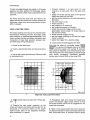
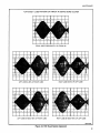
INDEX LAMP & SENSOR ALIGNMENT CHECK
After an index sensor or an index lamp assembly
has been replaced, or if disk drive-to-drive compatibility (disk exchangeability) problems arise,
check the index lamp and sensor alignment as
outlined.
1. Verify that the pointer on the front of the index
lamp assembly and the timing line on the index
sensor assembly line up exactly when the drive
door is closed.
2. Power up the drive.
3. Insert a CE disk (OUME P.N. 50235-02 or
50236-01).
4. Load the R/W heads against the disk and step
to track 01.
5. Set up a dual trace oscilloscope (Tektronix
465 or equivalent):
•
•
•
•
•
•
•
•
•
•
•
•
Connect channel 1 to PCB test point 1A;
connect channel 2 to PCB test point 1B;
connect scope ground to PCB test point GND;
set vertical deflection for both channels to
50mV/division;
set both inputs to AC;
add channels 1 and 2;
connect the external scope trigger probe to
PCB test point 3 (INDEX);
set trigger source to external;
select normal trigger mode;
select AC trigger coupling;
set nhorizontal sweep to 100 IAsec/division;
trigger on the leading edge (+) of the index
pulse.
6. Observe the timing between the start of a
sweep and the first peak of the index burst
(125 ± 5 transitions of 1F data). It should be
500lAsec ± 500lAsec for CE disk (OUME P.N.
50235-02) or 250lAsec ± 100lAsec for CE disk
(QUME P.N. 50236-01).
7. Step to track 76 and verify the same timing as
observed above between the start of a sweep and
the first peak of the index burst.
8. Select the other disk side and repeat steps 6
and 7 above.
9. Unload the R/W heads and remove the CE disk.
21
MAINTENANCE
Only if the index timing is outside the above tolerance, slightly loosen the screw that secures the
index sensor assembly to the mainframe and adjust the index sensor postion to obtain the specified timing; tighten the index sensor assembly
mounting screw .
TRACK S16 SENSOR ASSEMBLY SERVICE CHECK
1. Move the head/carriage assembly by hand all
the way against the stop at the rear of the drive
(away from spindle). This positions the heads at
track ~¢.
If this voltage is outside the stated tolerance,
replace the PCB as outlined under Printed Circuit
Board Removal and Replacement.
3. Check for + 1.0 to + 1.7 between PCB test
points B14 and GND.
4. Check between PCB test points A13 and GND
for + 4.0 to + 5.25V without a disk and the drive
door closed, and for 0 to 0.3V with an unprotected
disk (no write protect notch) installed and the
door closed.
5. Remove the disk.
2. Power up the disk drive.
3. Between PCB connector J2 pin B11 and GND
check for +5V ± 5%.
6. If any of the voltages measured in steps 3 & 4
are outside stated limits, replace the write protect
sensor assembly as per Write Protect Sensor
Assembly Replacement instructions.
If this voltage is outside the stated tolerance,
replace the PCB as outlined under Printed Circuit
Board Removal and Replacement.
IN USE LED SERVICE CHECK
4. Check for + 1.0 to + 1.7V between PCB test
points B12 and GND.
5. Check for 0 to + 0.3V between PCB test
points A11 and GND.
6. Power down the disk drive..
7. Move the head/carriage assembty by hand all
the way toward the disk spindle.
8. Power up the disk drive.
'9. Check for + 4.0 to + 5.25V between PCB test
points A11 and GND.
10. If any of the voltages measured in steps 4, 5, &
9 of the above procedures are outside the stated
limits, replace the track e~ sensor assembly as
per Track ~f1 Sensor Assembly Replacement instructions.
WRITE PROTECT SENSOR ASSEMBLY SERVICE
CHECK
'1. Power up the disk drive.
2. Between PCB connector J2 pin B13 and GND
check for + 5V ± 5%.
22
1. Power up the.the disk drive.
2. Check for + 5V ± 5%
points B15 and GND.
between PCB test
If this voltage is not present, replace the PCB as
outlined under Printed Circuit Board Removal and
Replacement.
3. Temporarily connect a jumper from PCB connector J2 pin A15 to GND. The In Use LED should
light up. Remove the jumper.
If the LED fails to light, replace it as per In Use
LED Removal and Replacement instructions.
4. If the LED checks out OK in step 3 above, but
fails to light during normal drive use with a disk instal/ed and the drive door closed, refer to tables
Factory Configuration of Options Traces, and Programmable Shunt Trace Functions and determine
PCB jumper status with respect to In Use LED
function.
5. Replace the PCB as outlined under Printed
Circuit Board Removal and Replacement if a functionalln Use LED fails to light as required with appropriate jumper and drive operating status.
MAINTENANCE
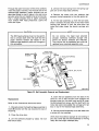
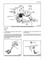
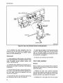
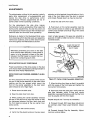
HEAD LOAD SOLENOID ASSEMBLY ADJUST·
MENT CHECK
This adjustment check is to be performed after
maintenance involving anyone of the following
assemblies: carrier, bail, head load solenoid, or
head/carriage. Also, if Read, Write, or Head Load
difficulties arise, these may be caused by a loss
of proper bail gap or head gap spacings.
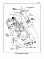
1. Position the disk drive on a stable flat surface, interior mechanism exposed, with drive
motor side up (PCB down). Orient it as shown in
the illustration below.
8. Slide the head/carriage assembly by hand all
the way to the other end of its range of travel
(track 76 position) toward the disk spindle.
9. Repeat steps 5 and 6 above.
10. Unload the heads and remove the disk from
the drive.
11. If the bail gap is within the stated tolerance
throughout the head/carriage assembly range of
travel, proceed to check the head gap as outlined
below.
If the baH gap is outside the stated tolerance, perform the bail gap adjustment as outlined under
Head Load Solenoid Assembly Adjustment.
12. Rotate the disk drive so that the right-hand
rear corner of the main frame casting with the
blue Qume type label is at the near edge of the
supporting surface (facing the operator).
13. Upright into the left-hand front corner of the
disk drive (the one farthest away), place a piece of
plain white paper.
14. Slide the head/carriage assembly by hand to
approximately track 40 position in the middle of
its range of travel (see Head/Carriage Assembly
Belt Clamp Access illustration under Steel Belt
Removal procedure).
008·A·051
Figure 19. Bail Gap Check
15. Close the drive door.
16. Load and unload the heads one time (see step
5 above).
2. Slide the head/carriage assembly by hand to
the end of its range of travel all the way toward the
rear of the disk drive (track i1J8 position).
3. Install a disk in the drive and close the drive
door.
4. Power up the disk drive.
5. Load the heads against the disk (this may be
done by a temporary jumper installed across test
points HA and GND on the PCB).
6. Check the gap between the metal bail plate
on the bail assembly and the plastic carriage arm
tab on the head/ carriage assembly. The gap
should be within 0.020 and 0.400 inch (0.5 to
1.0 mm).
17. Look at the gap between the unloaded R/W
heads by looking, from the right-hand rear corner
of the disk drive (over the idler assembly), through
the head/carriage assembly at the white paper
surface in the left-hand front corner.
The gap should be between 0.004 to 0.010 inch (0.1
to 0.25mm; the nominal thickness of one ANSI
standard disk is 0.003 inch/0.076mm).
- - - - - - - - CAUTION------The R/W head surfaces should not be
brought in contact with each other; avoid
this whenever possible, as it may cause head
damage.
Do NOT place any objects between the
heads to measure the head gap.
7. Unload the heads from the disk.
23
MAINTENANCE
If there is no gap between the heads, or if the gap
appears too wide, perform the head gap adjustment as outlined under Head Load Solenoid Adjustment.
18. Power down the disk drive and remove the
paper from the left-hand front corner; remove the
temporary jumper from across test points HA and
GND, if present.
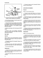
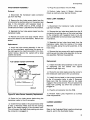
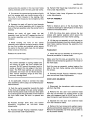
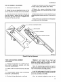
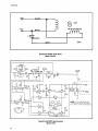
HEAD LOAD TIME CHECK
The head loading time should be checked after
maintenance involving the bail, bail base, head
load solenoid, or head/carriage assemblies. This
check verifies the free and proper movement and
interaction of head load solenoid plunger, bail, and R/W head lifting mechanism.
• Connect channel 1 to test point 1A and
channel 2 to test point 1B on the disk drive
PCB;
• attach the probe ground clips to the ground
(GND) test point on the PCB;
• set the vertical deflection for both channels to
50mV/div;
• set both inputs to AG;
• invert channel 2;
• add channel 1 to channel 2;
• set horizontal sweep to 10ms/div;
• attach the external trigger probe to programmable shunt jumper HL (head load) on
the disk drive PCB;
• select external trigger source;
• set the trigger coupling to AC and the trigger
mode to normal;
• preset the trigger for a positive slope.
4. Load the drive heads against the disk.
"'!!'""""'---....
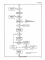
1. Power up the disk drive.
2. Insert a prerecorded disk and close th.e drive
door.
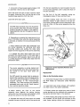
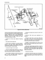
3. Use a dual trace oscilloscope (Tektronix 465
or equivalent) and:
This may be done by controller signal DRIVE
SELECT in a factory configured drive, or by HEAD
'['5'A'D controller signal with jumper B removed
and jumper C installed, or by disconnecting interface connector P1/J1 and closing a remote single
pole switch temporarily connected between
jumper pins HA and GN D on the drive PCB.
HEAD LOAD TIME 35ms MAX.
T
2 01 V. 1----+---:
1-_
5 olV. @ MIN.
PIP POINT
1
a
b
008·A·052
Figure 20. Head Load Time Check
5. Se1ltt a disk side and track with 1F data pattern. \
6. Observe the read signal waveform on the
scope and adjust the scope vertical gain for an
amplitude of 5 divisions (100 % ) at the lowest
peak-to-peak point of the displayed envelope.
(see illustration "a" above).
24
7. Repeatedly load and unload the heads and
adjust the scope's trigger slope control so that
the scope display trace will be triggered by the
head load command.
8. Read on the scope screen the time it takes for
the signal envelope to reach and remain above the
80 % amplitude point (2 divisions -above center
MAINTENANCE
line) from the beginning (trigger point) of the
display trace. This head loading time must be less
than or equal to 35 ms as shown in illustrati~n b
above.
9. Write 1F data (all "0") on track 76.
9. Select a track with 1F data pattern on the se·
cond disk side and repeat steps 7 and 8 above.
11. Divide the 2F read amplitude by the 1 Fread
ampUtude. Minimum acceptable ratio is 0.4
(or 40%).
10. Disconnect the oscilloscope from the disk
drive; remove the prerecorded disk; restore the
PCB jumper status as required for system operation.
if the head load time of 35 ms is exceeded on
either disk side, check for a binding solenoid
plunger, binding bail hinge, or improperly adjusted bail gap or head gap; if none of these are
the cause, the head/carriage assembly may need
to be replaced.
10. Read the just recorded 1F signal and note the
display amplitude on the scope.
12. Select the other disk side (second R/W head)
and repeat steps 5, 6, and 8 through 11 above.
13. Move the scope probe from test point 1A to
test point 1B and repeat the above procedure
for both disk sides (both R/W heads).
14. Unload the R/W heads from the disk.
15. Remove the R/W disk from the drive.
16. Disconnect the oscilloscope from the disk
R/W HEAD READ AMPLITUDE CHECK
1. Power up the disk drive.
2. Verify good track alignment (refer to R/W
Head Track Alignment.
3. Insert a good quality Qume Certified R/W Disk
(P.N.50151 ..01).
4. Select a disk side and load the R/W heads onto the disk.
5. Step to track 76 and write a 2F data signal (all
"1 ").
6. Read the just recorded 2F signal.
7. Connect an oscilloscope (e.g. Tektronix model
465 or equivalent):
-Vertical input probe (channel 1) to test point
1A;
..
- the probe ground to the ground (GND) test
point on the PCB;
-set vertical deflection to 50 mV/division;
-select AC input;
-set the trigger source to internal;
- set the trigger mode to normal;
-select DC trigger coupling;
-set the horizontal sweep to 0.5 msec.ldivision;
-trigger on the (channel 1) input signal.
8.
Note the amplitude of the displayed read
signal; it should be at least 100 mV pp if the
R/W disk is good.
drive.
If anyone of the four above ratios falls below
400/0, the head/carriage assembly needs to be
!eplaced, provided this is not caused by an increased head gap, faulty head azimuth, the head
lifting off the disk surface, or by poor track alignment or worn media (disk surface). Perform R/W
Head Azimuth Check, Head/Carriage Assembly
Radial Alignment check, and use an alternate Cer·
tified R/W Disk before replacing the head/carriage
assembly as outlined under Removal and
Replacement Procedures.
Do NOT omit the
checks and adjustments listed at the end of the
replacement procedure.
......-------NOTE-------The head/carriage assembly is factory ad. justed and tested. In the field there must be
no adjj.Jstment or repair attempted on the entire he'ad/carriage assembly.
READIWRITE (RIW) HEAD AZIMUTH CHECK
The R/W head azimuth significantly influences
the signal amplitude of recorded and of read data.
A head azimuth within ± 12 min. of zero is typical,
while the head/carriage assembly needs to be
replaced if the azimuth exceeds ± 18 min. Head
azimuth cannot be adjusted.
1. Power up the disk drive.
2. Insert a CE alignment disk (QUME P.N.
50235-02 or 50236-01) in the drive and close the
drive door.
25
MAINTENANCE
3. Load the R/W heads onto the CE disk.
4. Select a disk side.
5. Step the head/carriage assembly to track 76.
6. Use a dual trace oscilloscope (Tektronix 465
or equivalent) and:
-Connect channel 1 to test point 1A and channel
2 to test point 1B on the disk drive PCB;
-attach the probe ground clips to the ground
(GND) test point on the PCB;
-set the vertical deflection for both channels to
50mV/div;
-set both inputs to AC;
-invert channel 2;
-add channel 1 to channel 2;
-set the horizontal sweep to O.5ms/div;
-attach an external trigger to test point 3 (index
26
timing) on the PCB and set the trigger source
to external;
-set the trigger coupling to AC and the trigger
mode to external;
- t rigger on the leading edge of the index pulse.
7. Compare the wave form displayed to the
Azimuth Check illustration below. If the displayed
wave form is not within ± 18 minutes, the
head/carriage assembly needs to be replaced.
8. Select the other disk side to test the second
head and repeat step 7.
9. Unload the R/W heads.
10. Remove the CE disk from the drive.
11. Disconnect the oscilloscope from the disk
drive.
MAINTENANCE
2
3
4
MAXIMUM ALLOWABLE AZIMUTH ERROR OF
+ 18 MINUTES. BURST #4 IS 25% LARGER IN
AMPLITUDE THAN BURST #3.
2
3
4
TYPICAL AZIMUTH ERROR OF + 12 MINUTES.
BURSTS #3 AND #4 ARE EQUAL IN AMPLITUDE.
2
3
4
AN OPTIMUM ALIGNMENT OF ZERO MINUTES
AZIMUTH ERROR. BURSTS #1 AND #4 ARE
EQUAL IN AMPLITUDE. AS ARE BURSTS #2
AND #3.
1
2
3
4
TYPICAL AZIMUTH ERROR OF -12 MINUTES.
BURSTS #1 AND #2 ARE EQUAL IN AMPLITUDE.
2
3
4
MAXIMUM ALLOWABLE AZIMUTH ERROR OF
-18 MINUTES. BURST #1 IS 25% LARGER IN
AMPLITUDE THAN BURST #2.
USING A QUME CERTIFIED 12 MINUTE CE DISK (QUME P.N. 50235-02 OR 50236-01) THE
AZIMUTH SHALL BE ACCEPTABLE IF A DRIVE SHOWS LESS THAN THE MAXIMUM
ALLOWABLE 18 MINUTE AZIMUTH. THE MAXIMUM ALLOWABLE AZIMUTH IS CONSI·
DERED TO BE AnAINED WHEN BURST #11S 25% LARGER THAN BURST #2, OR IF BURST
#4 IS 25% LARGER THAN BURST #3.
003·A·009
Figure 21. Azimuth Check
27
MAl NTENANCE
REMOVAL AND REPLACEMENT
PROCEDURES
For the procedures outlined in this section, top
and bottom interior mechanisms of the disk drive
must be accessible. Supply cables for AC and DC
power to the drive unit are to be disconnected
from their respective connectors (JO and J5) in the
drive. A disk must not be installed in the drive
unless specifically instructed otherwise.
2. While turning the belt drive pulley by hand,
guide the drive belt so that it will rise up and over
the edge of the drive pulley.
3. Loosen the allen head setscrew in the drive
pulley and slide the pulley from the motor shaft.
Replacement
Reference is made to the Illustrated Parts LacaHons drawings whcih identify parts and assembly
names and locations, and to numerous detail illustrations in this section.
, . . . - - - - - - - C A U T I O N - - - - - -.......
Whenever performing any work on the disk
drive with the disk removed, a clean piece of
paper is to be inserted in place of the disk
between the R/W heads to prevent their sur·
faces from contacting each other.
Refer to the illustration below.
1. Slide the drive pulley onto the motor shaft and
align the pulley setscrew with the flat surface on
the shaft. Bring the top face of the drive pulley
flush with the top of the motor shaft and tighten
the setscrew.
GROOVE IN 50Hz
PULLEY ONLY
NOT IN 60Hz
ALIGN TOP OF DRIVE PULLEY
WITH TOP OF MOTOR SHAFT
PULLEY \
PRINTED CIRCUIT BOARD (PCB)
Removal
Refer to sheet a of the Illustrated Parts Locations
drawings for identification of items and locations
mentioned below.
1. Disconnect the interface cable, transducer
cable, and R/W head cable from their respective
PCB connectors (J1, J2, J3).
2. Remove the two screws which secure the
PCB to the main frame casting along the edge of
the interface connector (J1), and loosen the remaining two screws.
3. Slide the PCB edge out from under the two
loosened screws and lift the PCB out of the drive.
008·A·024
Figure 22. Drive Pulley Installation
2. Replace the drive belt, then rotate the spindle
pulley counterclockwise by hand to verify that the
belt is riding centered on the spindle pulley and
drive pulley surfaces.
3. Install the PCB as outlined under PCB
Removal and Installation and restore all connec·
tions.
BAIL ASSEMBLY
Replacement
Removal
1. Reverse the above procedure for re-installation of the PCB.
SPINDLE DRIVE BELT AND DRIVE PULLEY
Refer to the illustrations below.
Removal
1. Manually slide the head/carriage assembly all
the way towards the rear of the drive (track 0¢
position).
1. Remove the PCB as outlined under PCB
Removal.
2. Cut a strip of clean paper (approximately 2 X 8
in.) and fold it end-to-end to half length.
28
MAl NTENANCE
3. Unh00k the bail spring from the spring support arm on the head load solenoid.
Through the open front door of the drive, carefully
insert the paper, fold first, into the disk slot of the
head/carriage assembly (paper doubled over as
described tends to stay in place in the slot more
securely when the unit needs to be set on its side,
than a single straight strip of paper; providing
more reliable R/W head protection). Leave the
drive door open.
4. Rem,ove the screw with two washers that
secures the bail assembly to the disk guide rail.
5. Tilt the bail assembly up from the bail base,
slide it towards the side wall of the main frame
casting and remove it from the drive after the
metal bail plate clears the plastic carriage arm
tab.
. . . . - - - - - - - CAUTION------....
. . . . . . - - - - - - - NOTE - - - - - - -....
The R/W head surfaces must not be permitted to contact each other. Be sure that the
paper remains betwen the heads in the
head/carriage assembly disk slot throughout
this procedure.
Do not remove the head load solenoid
plunger. Solenoid, solenoid plunger and
shims are factory selected and matched.
They should not be separated and must be
replaced as a complete assembly only.
HEAD LOAD
SOLENOID ARM
\
\
008·A·025
Figure 23. Bail Assembly Removal and Replacement
Replacement
Refer to the illustrations above and below.
1. Manually place the head/carriage assembly in
track ~~ position (all the way towards the rear of
the drive).
4. Insert the bail assembly from the side of the
drive at a tilt so that the bail hook engages the
plunger cross-pin, the back stop spring is under
the bail adjustment screw, and the shelf with the
metal bail plate rests under the carriage arm tab
(but on top of the head/carriage assembly).
5. Secure the bail assembly to the bail base with
a screw with two washers.
2. Close the drive door.
3. Lift the solenoid plunger by about 1/2 inch
and hold it there.
Verify that the solenoid plunger is not binding in
any way; verify that the bail assembly is moving
freely and has slight sideways play.
29
MAINTENANCE
3. Proceed through the Bail Assembly Replacement as outlined above.
DRIVE MOTOR ASSEMBLY
Removal
Refer to the illustration below.
~
,.,,~~~
1. Proceed through PCB Removal and Spindle
Drive Belt and Drive Pull'ey Removal as outlined
above.
BAIL~
SPRING \.
\'
008·A·026A
Figure 24. Bail Assembly Re-Installation
6. Hook the bail spring to the spring support arm
on the head load solenoid.
7. Open the drive door and again verify freedom
.of movement of the solenoid plunger and of the
bail assembly. Refer to the Head Load Solenoid
Adjustment procedure if the solenoid plunger
should be binding.
8. Remove the paper strip from between the R/W
heads.
9. Perform Head Load Solenoid Adjustment
Check and Head Load Time Check as outlined
under Service Checks.
2. Remove the screw and two washers securing
the blue AC connector ground lead to the main
frame casting.
3. Remove the AC connector from the connector
bracket by compressing from the front the two
clips which hold the connector in its bracket. Use
pliers.
4. Remove the two screws with captive washers
securing the capacitor and clamp to the main
frame.
5. Remove the three screws and washers securing the drive motor to the main frame and lift out
the drive motor assembly.
Replacement
Refer to the illustration below.
BAIL BASE
Removal
Refer to sheet e of the Illustrated Parts Locations
drawings for identification of items and locations
mentioned below.
1. Proceed through Bail Assembly Removal as
outlined above.
2. Remove the screw with captive washers that
secures the bail base to the main frame casting.
3. Lift out the bai I base.
1. Install the drive motor on the main frame by
pushing the motor against the main frame stops
and securing it with three screws with captive
washers.
2. Mount the capacitor and clamp to the main
frame with two screws with captive washers.
3. Install the AC connector by pushing it into the
AC connector bracket. The clips on either side of
the connector will secure it.
4. Secure the blue AC connector ground lead to
the main frame with a screw (nickel plated),
washer, and star washer.
Replacement
1. Install the bail base in the drive, inserting the
bail base tip into the horizontal guides on the inside of the front bezel.
2. Secure the bail base with a screw with captive
washers.
30
5. Proceed through Spindle Drive Belt and Drive
Pulley Replacement and re-install the PCB as
outlined above.
MAINTENANCE
CAPACITOR
AND CLA,MP
AC CONNECTOR
...
BRACKET
NICKEL PLATED~
SCREW ~
'I·
•
I
I
AC CONNECTOR
GROUND LEAD
(BLUE)
I
AC CONNECTOR
CLIP
AC CONNECTOR
MAIN
FRAME
008-A-026B
Figure 25. Drive Motor Assembly Removal and Replacement
IN USE LED
Removal
1. Disconnect the transducer cable connector
(J2) from the PCB.
3. Separate the two In Use LED leads from the
transducer cable.
2. Remove the two In Use LED leads from the J2
connector by pushing down on the LED lead tabs
in the connector with tweezers: black to J2-A15,
red to J2-B15 (see Connector Lead Removal illustration below).
4. Pull the collar off the LED holder, then pull the
holder off the LED (refer to the illustration below).
'LED HOLDER
FRONT BEZEL
008·A·027
Figure 26. Connector Lead Removal (typical)
Figure 27. In Use Led Removal and Replacement
31
MAINTENANCE
Replacement
"I. Insert the LED holder from the front into the
LED hole in the front bezel. Slide the collar over
the In Use LED and onto the wires. With the holder
in the front bezel hole, push the LED into the
holder from behind, until it snaps into place.
Secure the LED holder by pushing the collar over
the holder (refer to the In Use LED Removal and
Replacement illustration above).
2. Route the two In Use LED leads along the
transducer cable to the J2 connector.
3. Install the two leads in their proper locations
in theJ2 connector (refer to step 2, Removal).
Make sure that the locking tabs on the leads
engage in the connector slot. This will prevent the
leads from pushing out when the connector is
plugged in.
2. Route the four sensor leads along the
transducer cable to the J2 connector.
3. Install the leads in their proper locations in
the J2 connector (refer to step 3, Removal). Make
sure that th"e locking tabs on the leads engage in
the connector slot. This will prevent the leads
from pushing out when the connector is plugged
in.
4. Plug the J2 connector into the PCB.
5. Install the bail assembly as outlined under
Bail Assembly Replacement.
TRACK
J1iJ SENSOR
Removal
1. Disconnect the transducer cable connector
(J2) from the PCB.
4. Plug the J2 connector into the PCB.
WRITE PROTECT SENSOR
Removal
1. Remove the bail assembly as outlined under
Bail Assembly Removal.
2. Disconnect the transducer cable connector
(J2) from the PCB.
3. Remove the four write protect sensor leads
from the J2 connector by pushing down on the
SEmsor lead tabs in the connector with tweezers:
blue to J2-A14, orange to J2-B14, black to
J2-A13, red to J2-B13 (refer to the Connector
Lead Removal illustration).
4. Separate the four write protect sensor leads
from the transducer cable. Note the routing of the
leads from the cable to the sensor.
5. Remove the screw with captive washers
which secures the write protect sensor assembly
to the main frame casting. Remove the assembly.
Replacement
1. Install the write protect sensor assembly on
the main frame, making sure the peg on the bottom of the assembly is in the main frame hole.
Secure the assembly with a screw with captive
washers.
32
2. Remove the four track r;J~ sensor leads from
the J2 connector by pushing down on the sensor
lead tabs in the connector with tweezers: blue to
J2-A12, orange to J2-B12, black to J2-A11, red to
J2-B11 (see the Connector Lead Removal IIlustra"tion).
3. Separate the four track ¢~ sensor leads from
the transducer cable.
4. Remove the screw with captive washers
which secures the track g~ sensor assembly to
the main frame casting. Remove the assembly.
Replacement
1. Install the track 00 sensor assembly on the
main frame, making sure the two pegs on the bottom of the assembly are in the main frame holes.
Secure the assembly with a screw with captive
washers.
2. Route the four sensor leads along
transducer cable to the J2 connector.
the
3. Install the four leads in their proper locations
in the J2 connector (refer to step 2, Removal).
Make sure that the locking tabs on the leads
engage in the connector slot. This will prevent the
leads from pushing out when the connector is
plugged in.
4. Plug the J2 connector into the PCB.
MAINTENANCE
INDEX SENSOR ASSEMBLY
4. Plug the J2 connector into the PCB.
Removal
5. Perform Index Lamp & Sensor Alignment
Check as outlined under Service Checks.
1. Disconnect the transducer cable connector
(J2) from the PCB.
INDEX LAMP ASSEMBLY
2. Remove the four index sensor leads from the
J2 connector by pushing down on the sensor lead
tabs in the connector with tweezers: black to
J2-A7, red to J2-B7, blue to J2-A6, orange to
J2-B6 (see Connector Lead Removal illustration).
3. Separate the four index sensor leads from the
transducer cable.
4. Remove the screw and large washer which
secure the sensor to the mainframe. Remove the
sensor.
Replacement
1. Install the index sensor assembly in the cutout on the mainframe, positioning the sensor to
the right against the mainframe (refer to the illustration below). Secure the sensor with a large
washer and screw.
PUSH SENSOR AGINST MAIN FRAME
•
1. Disconnect the transducer cable connector
(J2) from the PCB.
2. Remove the two index lamp leads from the J2
connector by pushing down on the lamp lead tabs
in the connector with tweezers: black to J2-A8,
red to J2-B8 (refer to the Connector Lead Removal
illustration).
3. Separate the two index lamp leads from the
transducer cable. Note the routing of the leads
from the cable, along the carrier assembly, to the
index lamp.
4. Rem'ove the two screws with captive washers
which secure the index lamp assembly to the car·
rier assembly. Remove the assembly.
Replacement
1. Install the index lamp assembly on the carrier
by tightening the two screws with captive
washers finger tight only.
2. Route the two lamp leads along the carrier to
the transducer cable and to the J2 connector.
3. Install the two leads in their proper locations
in the J2 connector (refer to step 2, Removal).
Make sure that the locking tabs on the leads
engage in the connector slot. This will prevent the
leads from pushing out when the connector is
plugged in.
022·A·01
4. Plug the J2 connector into the PCB.
Figure 28. Index Sensor Assembly Replacement
5. Perform Index Lamp Alignment as outlined
under Adjustments.
2. Route the four index sensor leads along the
transducer cable to the J2 connector.
CARRIER ASSEMBLY
3. Install the 'four leads in the J2 connector (refer
to step 2, Removal). Make sure that the locking
tabs on the leads engage in the connector slot.
This will prevent the leads from pushing out when
the connector is plugged in.
Removal
Refer to the Illustrated Parts Locations drawings,
sheet b, and to the illustration below.
33
MAINTENANCE
1. Cut a strip of clean paper (approximately 2 X 8
in.) and fold it end-to-end to half length.
While the drive front door is open, carefully insert
the paper, folded end first, into the disk slot of the
head/carriage assembly from the front.
LE~ave
the drive door open.
r-------- CAUTION------The R/W head surfaces must not be permitted to contact each other. Be sure the paper
remains between the heads in the head/carriage assembly disk slot throughout this procedure.
lifts the bail assembly) by hand towards the side
of the carrier assembly until it clears the hook of
the bail assembly.
Let the front of the bail assembly swing up,
disengaging ready off lever and bail hook.
5. While holding down the front of the bail
assembly slightly to gain access to the rear carrier screws, remove both screws, alternately a few
turns at a time. Lift the carrier assembly from the
drive unit.
READY
OFF LEVER
2. Depending on whether the index lamp is to remain in the disk drive while the carrier assembly
is removed, or whether it is to be removed with the
carrier:
INDEX
LAMP LEADS
!f
.. either release the index lamp assembly from
the carrier assembly by removing both lamp
mounting screws and pulling the index lamp
leads from their supports on the carrier underside,
.. or release the index lamp leads from the J2
connector by pushing down on the lead tabs in
the connector with tweezers: black to J2-A8, red
to J2-B8; separate the index lamp leads from the
transducer cable.
~------
CAUTION-------.
The carrier assembly is spring loaded and
will swing upward when the screws securi'ng
the carrier to the door latch plate are
removed.
Do NOT permit the carrier front to swing up
beyond the top edge of the front bezel as this
may cause serious damage to the R/W head
support springs in the head/carriage
assembly. The head springs are precision
preloaded and must not be flexed beyond
their normal operating range.
3. While holding the front of the carrier
assembly down against the spring tension,
remove the two front screws and washers which
secure the carrier to the door latch plate.
~~.
Squeeze the ready off lever (which is located
towards the rear on the bail side of the carrier and
34
008·A·048
Figure 29. Carrier Assembly Removal and
Replacement
Replacement
Refer to the illustration above.
1. Verify that the paper strip is present between
the R/W heads as instructed under Removal
above.
2. Insert both rear carrier screws with washers
into their holes in the carrier assembly.
3. Properly place the angled (top) ends of both
carrier springs into the notched-out recesses on
the carrier and hold them in that position.
4. While holding the spring top ends in their car. rier recesses, lift the carrier into position on the
main frame casting, sliding the straight (lower)
MAINTENANCE
spring ends into position in the two main frame
casting recesses under the rear guide bar clamp.
12. Perform R/W Head Gap Adjustment as outlined under Adjustments.
5. Counteract the upward spring tension slightly
and first engage both rear carrier screws only a
few turns in their threads in the casting, then
screw them in all the way but do not tighten at this
time.
13. Perform Index Lamp Alignment as outlined
under Adjustments.
poP-uP ASSEMBLY
Removal
6. Squeeze the ready off lever by hand towards
the side of the carrier assembly until it clears the
hook of the bail assembly when the carrier front is
lowered.
Release the ready off lever under the bail
assembly hook, but do NOT release the front of
the carrier assembly until the front screws are
installed.
7. While holding the front of the carrier
assembly down against the spring tension, install
the two front screws and washers which secure
the carrier to the door latch plate. Do not tighten
these screws at this time.
Refer to sheets band c of the Illustrated Parts
Locations drawings for identification of items and
locations mentioned below.
1. With the drive door open, remove the two
screws with captive washers which secure the
pop-up assembly to the main frame casting.
2. Lift the pop-up assembly up until the peg on
its underside (between the screw holes) clears the
main frame casting. Remove the assembly from
the drive unit.
Replacement
Release the carrier front.
1. Install the pop-up assembly by following the
Removal procedure in reverse order.
......- - - - - - C A U T I O N - - - - - -..
Make sure that the pop:-up assembly tip is inserted into the horizontal guides on the inside of
the front bezel.
The carrier assembly is spring loaded and
will swing up while the front screws are
removed. Do NOT permit the carrier front to
swing up beyond the top edge of the front
bezel. The R/W head springs are precision
preloaded and must not be flexed beyond
their normal operating range as this may
seriously damage them.
Hold the pop-up assembly pushed against the
side of the main frame casting while tightening
the screws.
2. Proceed through Pop-Up Assembly Adjustment as outlined under Adjustments.
DOOR LOCK SOLENOID
8. As applicable, install or connect the index
lamp assembly; refer to step 2 of the Removal procedures above.
9. Push the carrier assembly towards the back
of the drive and tighten the rear carrier screws.
Verify that the plastic ends on the door latch plate
do not bind against the guide tabs on the inside of
the front bezel when the door is opened and
closed.
10. Proceed through Drive Door and Carrier
Assembly Alignment as' outlined under
Adjustments.
11. Proceed through Pop-Up Assembly Adjustment as outlined under Adjustments.
Removarl
1. Disconnect the transducer cable connector
(J2) from the PCB.
2. Remove the two door lock solenoid leads
from the J2 connector by pushing down on the
tabs with tweezers: black to J2-A2, red to J2-B2,
(see Connector Lead Removal illustration).
3. Separate the two door lock solenoid leads
from the transducer cable.
4. Remove the two screws and washers securing the solenoid/hook assembly to the front bezel.
Remove the assembly and three springs (refer to
the Illustration below).
35
MAINTENANCE
FRONT
BEZEL
008-A-033
Figure 30. Door Lock Solenoid Removal and Replacement
s. To separate the hook assembly from the
solenoid, pullout the hook pin. Be careful not to
let the plunger with spring and padded washer
drop out of the solenoid coil.
5. Install the two leads in the J2 connector (refer
to step 2, Removal). Make sure that the locking
tabs on the leads engage in the connector slot.
This will prevent the leads from pushing out when
the connector is plugged in.
Replacement
6. Plug the J2 connector into the PCB.
1. Verify presence of the plunger in the solenoid
coil (note arrangement of plunger hardware in that
order: E-washer, spring, padded washer with
cushion facing spring).
FRONT BEZEL ASSEMBLY
Removal
2. Assemble hook assembly and solenoid by inserting hook pin (refer to the Door Lock Solenoid
illustration).
3. With the three springs in place (large spring in
the center), install the solenoid/hook assembly on
the front bezel. Secure the assembly with two
screws with washers.
4. Route the two door lock solenoid leads along
the transducer cable to the J2 connector.
36
Refer to sheet b of the Illustrated Parts Locations
drawings for identification of items and locations
mentioned below.
1. Release the door lock solenoid assembly
from the front bezel by removing two screws with
washers. Be careful not to lose any of the three
springs (see Door Lock Solenoid illustration).
2. Release the In Use LED from the front bezel
MAINTENANCE
assembly: pull the collar off the LED holder, then
pull the holder off the LED (refer to the In Use LED
illustration).
HEAD LOAD SOLENOID
3. Tie down the front of the carrier assembly
towards the main frame casting using some wire
or string, so that the drive door is in approximately
half open position.
Refer to the Illustration below.
- - - - - - - CAUTION-------.
The carrier assembly is spring loaded and
will swing up while the front screws are
removed. Do NOT permit the carrier front to
swing up beyond the top edge of the front
bezel. The R/W head springs are precision
preloaded and must not be flexed beyond
their normal operating range as this may
seriously damage them.
4. Remove the two screws and washers holding
the carrier assembly to the door latch plate of the
front bezel.
Removal
, . - - - - - - - - NOTE---------.
The position of the head load solenoid is
relatively critical and influences the proper
mechanical functioning of numerous components. Loosen the solenoid only if absolutely necessary.
1. Remove from the disk drive unit the PCB,
spindle drive belt, and the bail assembly as instructed in the respective removal procedures.
2. Remove the two head load solenoid leads
from the J2 connector by pushing down on the
solenoid lead tabs in the connector with tweezers:
black to J2-A1, red to J2-B1 (see Connector Lead
Removal illustration).
5. Remove the two screws with captive washers
which secure the front bezel to the main frame
casting. Lift the front bezel from the drive unit.
3. Separate the two head load solenoid leads
from the transducer cable.
Replacement
4. Move the head/carriage assembly by hand all
the way toward the spindle (forward).
1. Install the front bezel assembly on the main
frame by securing it with two screws with captive
washers.
2. Mount the front of the carrier assembly
against the door latch plate, using two screws
with washers. Do not tighten the screws at this
time.
3. Install the' In Use LED in the front bezel
assembly: insert the LED holder from the front into the LED hole in the front bezel; slide the collar
.over the LED and onto the wires; with the holder in
the front bezel hole, push the LED Into the holder
from behind until it snaps into place; secure the
LED holder by pushing the collar over the holder
(refer to the In Use LED Removal and Replacement illustration).
5. Remove the two screws with captive washers
which secure the head load solenoid to the
solenoid bracket. Access to these screws is
through two holes in the side of the main frame
casting.
6. Remove the solenoid adjusting screw (between the two screws which secure the solenoid
bracket to the main frame casting).
.....- - - - - - - N O T E - - - - - - -......
Do not let the plunger fall out of the head
load solenoid.
4. Install the door lock solenoid on the front
bezel as outlined under Door Lock Solenoid
Replacement above.
Plunger and shims are factory selected and
matched to the solenoid and are not exchangeable or replaceable by themselves.
Always replace the solenoid as a complete
assembly only.
5. Proceed through Drive Door and Carrier
Assembly Alignment as outlined under
Adjustments.
7. Remove the solenoid from the drive by dropping It down through the cutout in the casting.
37
MAINTENANCE
8. Release the solenoid bracket from the main
frame casting by removing the two screws with
washers.
5. Route the two head load solenoid leads along
the transducer cable to the J2 connector.
6. Install the two leads in the J2 connector (refer
to step 2, Removal). Make sure that the locking
tabs on the leads engage in the connector slot.
This will prevent the leads from pushing out when
the connector is plugged in.
7. Re-install the spindle drive belt and the PCB
as outlined in the applicable instructions.
8. Re-install the bail assembly as outlined
under Bail Assembly Replacement; perform Head
Load Solenoid Assembly Adjustment as outlined
under Adjustments.
DUST COVER AND WIPER
Removal
1. Proceed through Pop-Up Assembly Removal
as outlined above.
2. Remove the two screws with captive washers
which secure the dust cover to the stepper motor
flange. Lift off the cover.
3. If only the wiper is to be replaced, remove it
from the dust cover.
Replacement
1. Remove three screws and release the mounting bracket from the replacement solenoid
assembly.
STEEL BELT
~
WIPER
,..-------CAUTION------Do not exchange solenoid mounting
brackets or plungers by themselves as this
may cause solenoid performance problems.
Always replace the complete solenoid with
mounting bracket.
2. Mount the solenoid bracket to"the main frame
casting with two screws and washers, pushing
the bracket toward the center of the drive while
tightening the screws.
3. Install the solenoid by inserting it from below
through the main frame casting and mounting it
to the solenoid bracket with two screws with
washers. Do not tighten these screws at this time.
4. Loosely engage the solenoid adjusting screw
(see illustration above) but do not tighten.
38
DUST COVER
008·A·035
Figure 32. Dust Cover Removal and Replacement
Replacement
Refer to the illustration above.
1. If the wiper is being replaced, install the new
wiper in the dust cover by pushing it against the
MAINTENANCE
cover stop in the direction of the arrow on the
cover.
2. Install the dust cover loosely with the two
screws with captive washers on the stepper motor
flange.
3. Align the dust cover so that the exposed
wiper end lightly touches the steel belt. Secure
the cover in this position by tightening the two
screws.
4. Follow the Pop-Up Assembly Replacement
instructions to install the pop-up assembly; proceed. through Pop-Up Assembly Adjustment.
STeEL BELT
3. Move the head/carriage assembly by hand so
·that the steel belt/carriage cla.mp screws line up
with the access slot in the side of the main frame
casting (this is approximate "Track 40 Position~').
4. Using the access slot in the side of the main
frame casting, remove the two screws with captive washers and the clamp plate which secure
the steel belt. Note orientation of the clamp plate
(properly oriented the rounded clamp plate edges
must face the steel belt).
5. Push the slider on the idler assembly forward
against the tension spring. Insert a short Phillips
screwdriver into the now exposed hole in the main
frame casting. This maintains the slider in forward position with the tension released from the
steel belt.
Removal
- - - - - - - CAUTION-------
Refer to the illustrations below.
1. Remove the pop-up assembly as outlined
under Pop-Up Assembly Removal.
Do not let the tip of the screwdriver contact
the printed circuit board directly below.
- - - - - - - CAUTION - - - - - - Be careful not to kink the steel belt while
working with it.
0
0
0
2. Remove the dust cover from over the stepper
motor pUlley after removing the two screws with
captive washers.
0
0
HEAD/CARRIAGE ASSEMBLY
IN "TRACK 40 POSITION"
0
~
...
STEEL
BELT
..•.
_~'-_._._-_
~ ~
o
008·A·043
Figure 34. Steel Belt End Clamp Access
6. Rotate the stepper motor pulley
counterclockwise until the screw which secures
steel belt ends and clamp to the pulley is accessible with a screwdriver through the slot in the right
side of the main frame casting.
STEPPER
MOTOR
FLANGE
ACCESS SLOT IN MAIN FRAME
008·A·044
Figure 33. Head/Carriage Assembly Belt Clamp
Access
7. Remove the screw and clamp plate which
secure the steel belt ends to the stepper motor
pUlley.
8. Lift the steel belt ends from the stepper motor
pulley pin and remove the belt.
39
MAINTENANCE
IDLER ROLLER
008·A·045
Figure 35. Steel Belt/Stepp"er Mechanism
Note the belt ends arrangement on the pulley (the
"short" belt end from the head/carriage assembly
should be at the bottom, next to the pulley).
Replacement
Refer to the Illustrations above and below.
1. With the head/carriage assembly pulling tab
on the steel belt pointing up, install the steel belt
ends on the stepper motor pulley pin; "short" end
from the head/carriage side first. Loosely secure
the belt with the clamp and screw. Do not tighten
the screw at this time.
2. Push the slider on the idler assembly forward
against the tension spring and place the steel belt
over the idler roller (see Steel Belt/Stepper
Mechanism illustration above). Release the slider.
:i. By turning the stepper motor pulley back and
forth, check that the steel belt runs centered on
40
the idler roller throughout the belt's travel. Repeat
this step several times to be certain.
4. Turn the stepper motor pulley so that the
screw which secures the steel belt ends to the
pulley is accessible through the slot in the right
side of the main frame casting. Tighten the clamp
screw.
5. Position the head/carriage assembly so that
the belt clamp screw holes line up with the access slot in the side of the main frame casting (approximate "Track 40 Position").
8. By turning the stepper motor pulley, carefully
align the holes in the steel belt tab to be centered
over the threaded holes in the head/carriage
assembly.
7. Secure the steel belt to the head/carriage
assembly with the clamp plate and two screws
with captive washers.
MAINTENANCE
Replacement
1. Move the head/carriage assembly by hand to
track 76 position (all the way towards the drive
front).
2. Set the idler assembly in place on the main
frame casting and loosely secure it with two
screws with captive washers.
008·A·046
Figure 36. Steel Belt and Head/Carriage
Alignment
. . . - - - - - - - - - NOTE - - - - - - - - .
Be sure to have the side of the clamp plate
with the rounded edges come to lie against
the steel belt. This avoids stressing or warping the belt which might be caused if the
clamp plate's cutting burr is pressed against
the belt.
8. Perform Head/Carriage Assembly Radial
Alignment as outlined under Adjustments.
9. Install the dust cover over the stepper motor
pulley as outlined under Dust Cover and Wiper
Replacement.
10. Install the pop-up assembly as outlined
under Pop-Up Assembly Replacement; perform
Pop-Up Assembly Adjustment check.
IDLER ASSEMBLY
Removal
1. Move the head/carriage by hand all the way
forward towards the drive door (track 76 position).
2. Push the slider on the idler assembly forward
against the tension spring and lift the steel belt
from the idler roller (see Steel Belt/Stepper
Mechanism illustration above).
3. Remove the two screws with captive washers
which secure the idler assembly to the main
frame casting.
3. Push the idler assembly forward (toward the
stepper motor) and tighten the two screws.
4. Push the slider on the idler assembly forward
against the tension spring, and place the steel
belt over the idler roller.
5. Pull the steel belt back and forth to check that
it is running centered on the idler roller
throughout the belt's travel. Repeat this step
several times to be certain.
STEPPER MOTOR ASSEMBLY
Removal
Refer to sheets c and d of the Illustrated Parts
Locations drawings for identification of items and
locations mentioned below.
1. Disconnect the transducer cable connector
(J2) from the PCB.
2. Remove the five stepper motor leads from the
J2 connector by pushing down on the lead tabs in
the connector with tweezers: blue to J2-A5, red to
J2-A4, yellow to J2-B4, green to J2-A3, white to
J2-B3 (see Connector Lead Removal illustration).
3. Separate t~ five stepper motor leads from
the transducer cable and release them from the
main frame (two places).
4. Remove the pop-up assembly as outlined
under Pop-Up Assembly Removal.
5. Remove the dust cover from over the stepper
motor pulley after removing the two screws with
captive washers.
r------- CAUTION---------.
Be careful not to kink the steel belt while
working with it.
Remove the assembly.
41
MAINTENANCE
6. Proceed through Steel Belt Removal as outlined above.
7. Remove from the underside of the main frame
casting the two screws with captive washers
which secur~ the stepper motor.
3. Close the disk drive door.
4. Proceed through Printed
Removal as outlined above.
Circuit
Board
5. Remove the spindle drive belt as instructed
above.
Lift the motor out through the top of the drive.
Replacement
1. Install the stepper motor assembly on the
main frame and loosely secure it with two screws
with captive washers.
Do not tighten the screws at this time.
•
2. Secure the stepper motor leads to the main
frame (two places) and route them along the
transducer cable to the J2 connector.
3. Install the five leads in the J2 connector (refer
to step 2, Removal). Make sure that the locking
tabs on the leads engage In the connector slot.
This will prevent the leads from pushing out when
the connector is plugged in.
6. Release the head/carriage cable from the
main frame casting (one place).
7. Move the head/carriage assembly by hand so
that the steel belt/head carriage clamp screws
line up with the access slot in the side of the main
frame casting (approximate "Track 40 Position",
see Head/Carriage Assembly Belt Clamp Access
illustration).
8. Through the access slot in the main frame
casting remove the two screws with captive
washers and the clamp plate, to release the
head/carriage assembly from the steel belt.
9. Turn the idler roller by hand clockwise to position the pulling tab on the steel belt toward the
rear of the drive to the end of its range of travel
("Track 00 position").
4. Plug the J2 connector into the PCB.
5. Install the steel belt as instructed under Steel
Belt Replacement (perform Head/Carriage
Assembly Radial Alignment as outlined under Adjustments at the end of the steel belt installation).
10. Slide the head/carriage assembly by hand
toward the front of the drive to the end of its range
of travel.
. . . . . . . - - - - - - - NOTE - - - - - - -....
HEAD/CARRIAGE ASSEMBLY
Always handle the head/carriage assembly
gently.
Removal
1. Cut a strip of clean paper (approximately 1.5 X
6 in.) and fold it end-to-end to half length.
2. Through the open drive door insert the paper,
fold" first, from the front into the disk slot of the
head/carriage assembly (see Bail Assembly
Removal and Replacement illustration).
- - - - - - - CAUTION--------.
The R/W head surfaces must not be permitted to contact each other. Be sure that the
paper remains between the R/W heads in the
head/carriage assembly disk slot throughout
this procedure.
42
11. Release the two guide bar clamps (one on
each end of the two head/carriage guide rails) by
loosening their screws. Swing the guide bar
clamps off the head/carriage guide rails.
12. Push both head/carriage guide rails toward
the back of the drive until their front ends drop
down through the cut-out in the main frame
casting.
13. CAREFULLY drop the head/carriage assembly
with guide rails through the cut-out in the main
frame casting. Be careful not to let any of the
head/carriage assembly tabs or protrusions hang
up anywhere; do NOT force the head/carriage
assembly down.
MAINTENANCE
Replacement
1. Verify that the drive door is closed and that
the pulling tab of the steel belt is positioned
toward the rear of the drive at the end of its range
of travel.
while making sure that the head/carriage
assembly slides freely on the guide ralls.
, . . . . . - - - - - - CAUTION - - - - - -....
Do not kink or bend the steel belt by bumping
into the pull tab while sliding the head/carriage assembly back and forth .
. . . - - - - - - - CAUTION--------.
Be sure that a clean paper strip is present
between the R/W head surfaces of the
replacement head/carriage assembly as instructed under Removal procedures above.
2. Place the two guide rails in position on the
replacement head/carriage assembly with only
about 1/2 in. of the guide rails protruding from the
front of the head/carriage assembly.
3. With the drive resting on its side, insert
head/carriage assembly and rails from below
through the cut-out in the main frame casting,
long protruding (rear) ends of the rails first.
Be sure that the plastic carriage arm tab comes to
rest ON TOP of the metal bail plate (see the Bail
Assembly Removal and Replacement illustration).
4_ Place the ends of both guide rails Into position on their blocks on the main frame casting.
5. Swing the guide bar clamps (2) into position
atop the guide rail ends and tighten their screws
8. Re-install the spindle drive belt and the PCB
as outlined in the applicable instructions.
7. Proceed through all applicable steps outlined
under Steel Belt Replacement to properly secure
the stee'l belt to the head/carriage assembly.
. - - - - - - - - CAUTION--------.
To avoid damage to the drive, closely adhere
to the detailed steel belt Installation
InstructIons.
8. Perform Head Load Solenoid Adjustment
Check outlined under Service Checks before proceeding through the Head/Carriage Assembly
Radial Alignment as Instructed at the end of the
steel belt installation.
9. Perform Head/Carriage Assembly Radial
Alignment as outlined under Adjustments.
10. Perform R/W Head Read Amplitude Check
and R/W Head Azimuth Check as outlined under
Service Checks.
43
MAINTENANCE
ADJUSTMENTS
The adjustments outlined in this section typically
apply after replacement of subassemblies and
restore the disk drive to performance within
specifications. Periodic adjustments are not required under normal operating conditions.
For the adjustments the disk drive interior
mE~chanisms must be accessible. When specified
during some adjustments, AC and DC power are
to be applied to the drive as per the Interface Connections table for minimum drive operability.
Reference is made to the Illustrated Parts Locations drawings which identify parts and assembly
names and locations, and to other detail illustrations throughout the Maintenance section.
. . . - - - - - - - - CAUTION------.....
plate do not bind against the guide tabs on the inside of the front bezel when the door is opened
and closed. Repeat step 3 as may be .required.
5. Close the disk drive front door.
6. Push down on the carrier assembly near the
front carrier screws to obtain a gap between the
carrier cross member and the E-ring of the collet
assembly shaft.
Insert a feeler gauge in the gap and establish a
gap size of 0.020 to 0.060 inch (0.5 to 1.5mm) as illustrated below.
CHECK FOR GAP OF
0.020 TO 0.060 INCH
(0.5 TO 1.5MM)
Whenever performing any work on the disk
drive with the disk removed, a clean piece of
paper is to be inserted in place of the disk
between the R/W heads to prevent their surfaces from contacting each other.
DRIVE MOTOR PULLEY POSITIONING
Proper positioning of the drive pulley on the disk
drive motor shaft is described under Spindle Drive
Belt and Drive Pulley Replacement.
DF~IVE
DOOR AND CARRIER ASSEMBLY ALIGN-
MIENT
For this procedure the two screws which mount
the rear of the carrier assembly to the main frame
casting, and the two screws which mount the
front of the carrier assembly to the door latch
plate should be only finger tight.
1. Power down the disk drive.
2. Open the disk drive front door.
3. While pushing the carrier assembly towards
the rear of the disk drive, align the carrier so that
the distances between the door latch plate and
the front bezel are equal at the two carrier front
screw points.
008-A-032
Figure 37. Carrier-Collet Assembly Adjustment
7. Align the" drive front door so that it is parallel
with the recess of the front bezel and tighten the
two carrier front screws.
.
8. Open and close the drive door. Verify that the
gap size between collet E-ring and carrier
assembly is as specified above, and that the front
door is parallel with the front bezel.
Repeat steps 6 and 7 as may be necessary.
9. Proceed through R/W Head Gap Adjustment
as outlined under Head Load Solenoid Adjustment.
Tighten the two rear carrier screws.
4. Verify that the plastic ends on the door latch
44
10. Proceed through Pop-Up Assembly Adjustment as outlined below.
MAINTENANCE
4. Open the drive door to within approximately
1/4 inch of being fUlly opened; hold it there.
POP-UP ASSEMBLY ADJUSTMENT
1. Power down the disk drive.
5. Rotate the pop-up adjustment screw
counterclockwise until the pop-up slider is just
unlatched.
2. Rotate the pop-up adjustment screw on the
carrier assembly clockwise as much as possible.
6. Repeat steps 3 and 4 to verify reliable pop-up
unlatching when the door is within 1/4 inch of fully
open.
3. Close the drive door and latch the pop-up
slider by sliding it toward the rear of the drive
(away from the front door) until it engages under
the pawls of the pop-up lever.
7. Secure the pop-up setscrew with thread locking compound (e.g. Loctite #222).
pOP·Up ADJUSTMENT SCREW
op·Up ASSEMBLY
~_.-,o:::-~POP·Up
SLIDER (LATCHED)
008·A·047
Figure 38. Pop-Up Adjustment
HEAD LOAD SOLENOID ASSEMBLY
ADJUSTMENT
1. Position the disk drive on a stable flat surface, interior mechanism exposed, with drive
motor side up (PCB down).
2. Install a disk in the drive and close the drive
door.
3. If disconnected, restore power connections
. and power up the disk drive.
4. Perform bail gap adjustment as outlined:
• Slightily (1 turn) loosen the two head load
solenoid mounting screws. Access to these
screws is through holes in the side of the main
frame casting (see illustration below).
• Slide the head/carriage assembly by hand to
the end of its range of travel all the way toward the
rear of the disk drive (track gg position).
• Load the heads against the disk (this may be
done by a temporary jumper installed across test
points HA and GND on the PCB).
• Turn the solenoid adjusting screw in the
45
MAl NTENANCE
SOLENOID CLAMP BRACKET
SOLENOID
ADJUSTING SCREW
008·A·049
Figure 39. Bail Gap Adjustment
solenoid clamp bracket to adjust the gap between
the metal bail plate on the bail assembly and the
plastic carriage arm tab on the head/carriage
assembly. The gap must be between 0.020 and
0.040 inch (0.5 to 1.0 mm). Turning the screw
clockwise decreases the gap.
• Tighten the head load solenoid mounting
screws.
• Unload the heads and remove the disk from
the drive.
6. Perform
outlined:
R/W
head gap
adjustment
as
• Rotate the disk drive so that the right-hand
rear corner of the main frame casting with the
blue Qume type label is at the near edge of the
supporting surface (facing the operator).
• Re-check the bail gap size.
• Verify that the solenoid is mounted perpendicular to the main frame casting (head load
solenoid arm straight up-and-down) and that the
solenoid plunger is moving freely.
• Unload the heads from the disk.
• Slide the head/carriage assembly by hand all
the way to the other end of its range of travel
(track 76 position) toward the disk spindle.
• Again load the heads and verify that the bail
gap is within the above stated tolerance.· If
necessary, repeat the adjustment.
46
• Upright in the left-hand front corner of the
disk drive (the one farthest away), place a piece of
plain white paper.
• Slide the head/carriage assembly by hand to
approximately track 40 position in the middle of
its range of travel (see Head/Carriage Assembly
Belt Clamp Access illustration under Steel Belt
Removal procedur~).
• Close the drive door.
• Load and unload the heads one time (either by
controller command, or by temporarily installing a
jumper across test points HA and GND on the
PCB).
MAINTENANCE
• Look at the gap between the unloaded R/W
heads by sighting, from the right-hand rear corner
of the disk drive (over the idler assembly), through
the disk slot in the head/carriage assembly at the
white paper surface in the left-hand front corner.
If the head surfaces are in contact with each other
and there is no gap visible between them, load
and unload the heads one more time, since the
heads "stick" sometimes.
• If there still is no visible gap between the R/W
heads, do NOT repeat loading and unloading, but
back out the backstop screw in the carriage
assembly (see illustration below) counterclockwise about two turns. Open and close' the
drive door, then load and unload the heads; there
should now be a visible head gap.
, . . . . - - - - - - CAUTION
--------1
The R/W head surfaces should not be
brought in contact with each other; avoid
this whenever possible, as it may cause head
damage.
Do NOT place any objects between the
heads to measure the head gap.
dard diisk is 0.003 inch/0.076mm); it cannot be
measured and must be estimated. Carefully turn·
ing the backstop screw clockwise will bring the
R/W heads closer together.
• Open and close the drive door, then load and
unload the R/W heads again and verify proper
head gap spacing by sighting through the disk
slot in the head/carriage assembly as instructed
above. If necessary, repeat the adjusting
procedure.
• Power down the disk drive and remove the
paper from the left-hand front corner; remove the
temporary jumper from test points HA and GND, if
present.
• Secure the backstop screw with threadlocking
compound (e.g. Loctite #222).
6. Perform Head Load Time Check as outlined
under Service Checks to ascertain that head load
solenoid plunger or bail hinge are not binding.
INDEX LAMP ALIGNMENT
t. Close the disk drive front door.
2. Slightly loosen the two screws which mount
the index lamp assembly to the carrier assembly.
ANGLE OF VIEW
~
CARRIER ASSEMBLY
~~
CHECK FOR R/W
HEAD GAP OF 0.004
TO 0.010 INCH
(0.1 TO 0.25mm)
"INDEX 2"
2-SIDED----~;."\
DISCSENSO~
INDEX LAMP
ASSEMBLY
....
,
BACKSTOP SCREW
...." ...._.-- . ."
/
~'
.... ~
'.,
__- - - . . . /'"
Figure 40. R/W Head Gap
008·A·053
Adju~tment
008·A·029
Figure 41. Index Lamp Assembly Positioning
• Turn the backstop screw in the carrier
assembly (see illustration below) to adjust the
gap between the unloaded R/W heads. The gap
must be between 0.004 to 0.010 inch (0.1 to
0.25mm; the nominal thickness of one ANSI stan-
3. Align the pointer. on the front of the index
lamp assembly exactly with the timing line on the
index sensor assembly installed directly below on
the main frame.
47
MAINTENANCE
Tighten the two mounting screws while holding
the lamp assembly firmly against the carrier to
maintain the alignment.
in the side of the main frame casting.
STEPPER MOTOR PULLEY IN "TRACK 40 POSITION"
4. Proceed through Index Lamp and Sensor
Alignment Check as outlined under Service
Checks.
- . - - - - - - NOTE - - - - - - . . . . . . ,
Do NOT change the position of the index
sensor assembly; it must remain firmly
against the stop on the main frame casting.
BELTCLAMP~
ACCESS SLOT IN\
"
MAIN FRAME t r-""-'
}
,
I
~~-4--+-----:
I( 0
L,-----
FLANGE
TIMING
SLOT
PULLEY
TIMING
HOLE
---f: ;. . '- - - + - ,
I
1 ,
I
I
S1·EPPER MOTOR DUST COVER/WIPER
ADJUSTMENT
Access to and proper positioning of the stepper
motor dust cover and the steel belt wiper are
described under Dust Cover and Wiper Removal
and Replacement.
HEAD/CARRIAGE ASSEMBLY RADIAL
ALIGNMENT
This procedure establishes precise on-track positioning of the RIW heads. It is to be done on track
38 or 40, using a Qume certified two-sided CE
alignment disk (QUME P.N. 50236-01 or 50235-02
respectively). The following procedure references
track 40.
- - - - - - - - - - CAUTION--------.
The head/carriage assembly is factory adjusted and tested and is not field serviceable. Do not, for any reason, attempt to
make repairs or internal adjustments on this
assembly, or clean the R/W heads. This can
cause severe damage to the head surfaces
or to the recording media.
1. Remove the pop-up assembly as outlined
under Pop-Up Assembly Removal.
2. Place the disk drive on its side to orient it with
the screwdriver access slot in the side of the main
frame pointing up as shown in the Stepper Motor
Pulley Track 40 Alignment illustration below.
3. Move the head/carriage assembly by hand so
that the timing hole in the stepper motor pulley
lines up precisely above the timing slot in the
stepper motor flange. This is "Track 40 Position"
and is illustrated below.
In this position the steel belt/carriage clamp
screws also will be lined up with the access slot
48
IDLER
ASSEMBLY
MOTOR MOUNTING
SCREWS (BOnOM)
008.A.044
Figure 42. Stepper Motor Pulley Track 40 Alignment
4. If disconnected, restore power connections
and power up the disk drive.
5. Connect a temporary jumper across test point
pins T40 on the PCB. Verify that the stepper motor
pulley remained in "track 40 Position",
repeat step 3 above if necessary.
6. Use a dual trace oscilloscope (Tektronix 465
or equivalent) and:
• Connect channel 1 to test point 1A and channel
2 to test point 18 on the disk drive PCB;
• attach the probe ground clips to the ground
(GND) test point on the PCB;
• set the vertical deflection for both channels to
50mV/div;
• set both inputs to AC;
• invert channel 2;
• add channel 1 to channel 2;
• set the horizontal sweep to 20msldiv;
• attach an external trigger to test point 3
(INDEX) on the PCB and set the trigger source
to external;
• set the trigger coupling to AC and the trigger
mode to external.
. . . - - - - - - - - N O T E - - - - - - -.....
Before using the CE disk, allow a minimum
of 30 minutes for the disk to adapt to the ambient temperature in which it is to be used.
MAINTENANCE
"CAT EYES" LOBE PATTERN ON TRACK 40 USING QUM E CE DISK
EQUAL AMPLITUDE (EXACTLY ON TRACK 40)
LEFT LOBE IS 80% OF RIGHT LOBE
LEFT LOBE IS ABOUT 60% OF RIGHT LOBE
RIGHT LOBE IS 80% OF I-EFT LOBE
RIGHT LOBE IS ABOUT 60% OF LEFT LOBE
008·A·054
Figure 43. R/W Head Radial Alignment
49
MAINTENANCE
7. Insert a Qume certified CE alignment disk in
the drive and close the drive door.
center of its rotational adjustment range and
tighte,n the two mounting screws.
8. Load the R/W heads onto the CE disk and
select a disk side.
• Through the access slot in the side of the main
frame casting, slightly loosen the two screws with
captive washers which secure clamp plate and
steel belt to the head/carriage assembly.
- - - - - - - - C A U T I O N - - - - - -....
• Very carefully move the head/carriage
assembly to balance the radial alignment position
of the two R/W heads with each other as well as
possible, while still maintaining the 80 percent
alignment specification for each R/W head.
Do not record on the CE disk. Recording on
the CE disk will render it useless for alignment checks. A write protect notch has been
placed in the disk jacket to red'uce the
possibility of accidental recording.
9. Using the trigger slope level control, synchronize the scope to obtain (from the R/W head
of the selected side) the "cat eyes" disp!ay shown
in the R/W Head Alignment illustration.
The oscilloscope will display two amp'litude
lobes. The R/W head is correctly aligned when the
lobes are equal in amplitude, or at least within 80
piercent of each other. (refer to the R/W Head
Radial Alignment illustration).
10. If the lobes are not within 80 percent of each
other, loosen the two screws on the PCB ~ide of
the main frame which secure the stepper motor
and slowly rotate the stepper motor assembly until the lobes are of equal amplitude.
11. Select the second disk side and note the "cat
eyes" amplitude relationship.
1:2a. By turning the stepper motor assembly and
alternately selecting disk sides 0 and 1, balance
the radial alignment of the two RIW heads with
each other as much as possible while stili rer.naln·
ing within the 80 percent alignment specification
for each' R/W head. Balance the left lobe of R/W
head 0 with the right lobe of R/W head 1.
• Carefully tighten the two steel belt clamp
screws.
• If necessary, again loosen the two stepper
motor mounting screws and repeat step 12a
above to fine-tune the alignment, before continuing with the steps below.
13. Alternately tighten the two screws securing
the stepper motor assembly to the main frame a
little at a time to maintain the R/W head alignment.
14. Remove the temporary jumper from across
test point pins T40 on the PCB.
15. To check the accuracy of the alignment, step
to track 39 and back to track 40, and then step to
track 41 and ,back to track 40.
Note the difference in "cat eyes" amplitudes
which may result when approaching track 40 from
either direction.
If the 80 percent specification is exceeded by
either R/W head in either direction, loosen the
stepper motor mounting screws again and optimize the offset. In this case steps 12 and 13
above, followed by step 15, must be repeated.
16. Unload the R/W heads from the disk.
17. Remove the CE disk from the drive.
1:2b. If a balanced condition (within the 80 perc,ent specification) between both R/W heads cannot be obtained with the available rotational
range of the stepper motor (and only under this
circumstance), proceed as follows:
.. Set the stepper motor to the approximate
50
18. Disconnect the oscilloscope from the disk
drive.
19. Install the pop-up assembly as outlined
under Pop-Up Assembly Replacement; perform
Pop-Up Assembly Adjustment check.
MAINTENANCE
TROUBLESHOOTING
GENERAL
This section presents troubleshooting procedures
for the QumeTrak 842 Disk Drive. Aside from some
application related precorditions and a few functional prerequisites, troubleshooting a QumeTrak
842 is limited to tracking down the cause of oneof
the following basic malfunctions. Not Ready,
Seek Error, Read Error, Write Error, No Head Load.
Troubleshooting of these malfunctions is presented in flowchart format. Reference by title is
made in the flowcharts wherever one of the Service Checks or Adjustments sub-routines applies.
DEFINTION OF MALFUNCTION TERMS
1. NOT READY - the controller does not receive
an expected READY signal from the disk drive.
2. SEEK ERROR - the disk drive is unable to access a designated disk side or track, or to confirm
Track 00 access to the controller.
3. READ ERROR - the disk drive unit is unable to
recover properly data previously stored on a disk.
4. WRITE ERROR - the disk drive unit is unable
to record properly a data sequence on the disk.
5. NO HEAD LOAD - the R/W heads are not loaded against the disk surface when required.
situation but may also be detrimental to head performance.
"Hard" disk errors are permanent (or
non-recoverable) in nature. They are typically
caused by particles in excess of head gap size, or
by microscopic voids or pits in the disk surface,
resulting in error pulses or glitches in the recorded data. A soft error, when occurring during a
write cycle will cause a recorded hard error.
2. The most efficient way to find out whether a
malfunc,tion is caused by a defective drive is to
exchange a suspect unit with one known to be in
good working order. If a compatible exchange
QumeTrak 842 Disk Drive is available, its internal
jumper status should be checked for proper system configuration. To verify and establish jumper
compatibility, compare exchange and suspect
drive PCB's and refer to tables: Factory Configuration of Option Traces, Programmable Shunt Trace
Functions, Drive Select Options, and Head Select
Options, in this manual.
3. Verify that external connectors J1/P1 and
J5/P5, as weH as associated cables are drive compatible, in goo.d working order, and firmly attached at both ends.
4. Perform AC and DC power measurements as
outlined under Power Test below.
PREREQUISITE CHECKS
TROUBLESHOOTING PRECONDITIONS
1. Eliminate the possibility of the disk being the
cause of malfunction:
• Verify that the malfunction at hand is not
caused by a disk incompatible with the overall
system;
• verify that the disk is -inserted into the drive
facing the right way, Le. with the label on the disk
jacket facing toward the front door (facing away
from the' In Use LED on the front panel);
• use another disk known to have good data
recorded on it to determine whether a "soft" or a
"hard" error has occurred:
"Soft" disk errors are temporary (or recoverable)
reading errors. They are typically caused by contamination of the disk surface picked up in use
and handling. Repeated scanning of the disk surface with R/W heads loaded to it might cure the
All information and particularly the QumeTrak 842
flow charts presented in this Troubleshooting
Section are based on "Factory Configuration" of
the QumeTrak 842 unit as listed under Customer
Strappable Options in this manual, unless specifically stated otherwise.
When troubleshooting, identify the programmable
functions status of the defective drive unit by
comparing the drive's PCB jumpers to jumper
tables: Factory Configuration of Option Traces,
Programmable Shunt Trace Functions, Drive
Select Options, and Head Select Options. Also,
refer to the illustration PCB Jumper Locations,
Test Point & Connector Pin Assignments for rapid
identification of PCB locations. Deviation from
"Factory Configuration" may in some cases
result in drive performance significantly different
from that stated in the troubleshooting flow
diagrams.
51
MAINTENANCE
For troubleshooting the disk drive unit must be
fully energized, with its PCB and drive mechanisms
accessible. A pre-recorded disk with known good
system data andlor a Qume CE alignment disk
(QUME P.N. 50235-02 or 50236-01) is required.
multimeter and scope as required). To locate
measurement points, refer to illustration PCB
Jumper Locations, Test Points and Connector Pin
Assignments.
J5, pin 1 to GND on the PCB: + 24V ± 10%; max.
ripple 0.1V PIP;
POWER TEST
1.. Check for presence of AC power at connector
JO, across pins 1 and 3. AC potentials and
tolerances are stated in table Installation Requirements in the Installation section. Refer to illustration PCB Jumper Locations, Test Points and
Connector Pin Assignments.
2. Check DC potentials as listed below (use
J5, pin 5 to GND on the PCB: + 5V ± 5%; max.
rl pple 0.05V PIP;
TP+ 17 to GND on the PCB: + 16.40V to + 17.60V;
TP + 12 to GND on the PCB: + 11.4V to + 12.6V;
TP + 6 to GND on the PCB: + 5.48V to 5.82V.
TROUBLESHOOTING FLOW CHARTS
These Troubleshooting Flow Charts begin on the Following pages:
52
Fig. 44 Power Failure page 53
Fig. 47 Read Error page 59
Fig. 45 Nat Ready page 54
Fig. 48 Write Error page 62
Fig. 46 Seek Error page 56
Fig. 49 No Head Load page 65
MAINTENANCE
MEASURE AC
POWER @ J9·1&·2
SEE "POWER TEST"
NO
MEASURE DC
POWER, SEE
"POWER TEST"
CHECK SYSTEMI
AC SOURCE
VERIFY
FIX
NO
CHECK SYSTEMI
DC SOURCE
NO
REPLACE
PCB
*
* see Removal
and Replacement Procedures
Figure 44. Power Failure Troubleshooting Routine
53
MAINTENANCE
CHECK DISK
DRIVE MOTOR &
PHASE SHIFT
CAPACITOR
CHECK
INDEX STATUS
(TEST PAD I)
CHECK SYSTEM
CONTROLLER
CORRECT
JUMPER
CONFIGURATION
REPLACE
P.C.BOARD
*
CHECK INDEX LAMP
& SENSOR ASS'IES
(A7= 1·SIDED)
(A6= 2·SIDED) 1r *
REPLACE INDEX
LAMP OR SENSOR
1r
1r
see Removal and Replacement Procedures
* * see Service Checks
Figure 45. Not Ready Troubleshooting Routine
54
MAINTENANCE
CHANGE TO
RIGHT PULLEY
*
CHECK SPINDLE
DRIVE BELT
REPLACE
BELT
CHECK SPINDLEI
PULLEY & COLLET
ASS'IES FOR
MECH. BINDS
REPLACE MECH.
REPLACE
P.C. BOARD
SUB·ASS'IE~
AS REQUIRED
*
*
* see Removal
and Replacement Procedures
Figure 45. (continued)
55
MAINTENANCE
PROCEED TH RU
"NOT READY"
ROUTINE
PROCEED THRU
"NO HEAD LOAD"
ROUTINE
CHECK SIGNALS
RECEIVED FROM
CONTROLLER
1ST; : J1-36 <O.4V & >3m SEC.)
- - DIRECTI N ~1'34,>2.4V)
SIDE SELEC (J1·14, >2.4V)
YES
CHECK
CONTROLLER
* see
Removal and Replacement Procedures
Figure 46. Seek Error Troubleshooting Routine
56
MAl NTENANCE
CH ECK TRAcK fi¢
DRIVE OUTPUT
(J1·42)
CHECK TRACK ~~
SENSOR ASSEMBLY
(J2·A11)
*'*
REPLACE
SENSOR ASS·Y.
'*
REPLACE
DRIVE P.C. BOARD
'*
PROCEED THRU
"READ ERROR"
ROUTINE
3
CHECK DIRECTION
(J1·34) SIGNAL FROM
CONTROLLER
REPLACE DRIVE
P.C. BOARD
'*
2
* see Removal and Replacement
* * see Service Checks
Procedures
Figure 46. (continued)
57
MAINTENANCE
NO
SELECT ALTERNATELy TO INNER,
OUTER, & CTR.
TRACKS
PERFORM HEAD/
CARRIAGE ASS'Y.
RADIAL AlIGNMT.
•••
REPLACE
STEEL BELT •
REPLACE HEAD
CARRIAGE AND/OR
GUIDE RAILS
•
REPLACE IDLER
ASSEMBLY •
REPLACE
STEPPER MOTOR.
REPLACE P.C.
BOARD·
SEEK TO
TRACK ~0
'" see Removal and Replacement Procedures
'" '" see Service Checks
'" '" '" see Adjustments
Figure 46. (continued)
58
MAINTENANCE
CHECK I
LET
(J1·14) FROM CON·
TROLLER
SIDE 0 = TRUE< O.4V
SIDE 1 = FALSE> 2.4V
NO
REPLACE HEADI
CARRIAGE ASS·Y.
*
PROCEED THRU
"NOT READY"
ROUTINE
PROCEED THRU
"NO HEAD LOAD"
ROUTINE
CHECK TRACK jj
(J1·42) SIGNAL
STATUS
* see
Removal and Replacement Procedures
Figure 47. Read Error Troubleshooting Routine
59
MAINTENANCE
PROCEED TH RU
"SEEK ERROR"
ROUTINE
PROCEED THRU
"SEEK ERROR"
ROUTINE
3
PERFORM
HEAD/CARRIAG E
ASS'Y. RADIAL
ALIGNMENT
***
PROCEED THRU
"SEEK ERROR"
ROUTINE
PERFORM
HEAD/CARRIAGE
ASS'Y. RADIAL
ALIGNMENT
***
* see Removal and Replacement
* * see Service Checks
* * * see Adjustments
Figure 47. (continued)
60
Procedures
MAINTENANCE
2
CHECK FOR
READ DATA OUT·
PUT (J1-46)
CHECK CONTROLLER
PERFORM R/W HEAD
READ AMPLITUDE
CHECK
**
REPLACE DRIVE
P.C. BOARD *
REPLACE DISK
REPLACE HEADI
CARRIAGE ASS'Y.
REPLACE DRIVE
·P.C. BOARD *
* see Removal and Replacement
* * see Service Checks
* * * see Adjustments
Procedures
Figure 47. (continued)
61
MAINTENANCE
USE NON·PRO·
TECTED DISK
REPLACE DISK
CHECK SIDE SELECT
(J1·14) FROM CON·
TROLLER
SIDES = TRUE < O.4V
SIDE1
FALSE >2.4V
=
NO
~---__.....
CHECK CONTROLLER
REPLACE DRIVE
P.C. BOARD
NO
*
INSERT PRERECOR·
OED DISK & CLOSE
DOOR
SELECT DRIVE
PROCEED THRU
"NOT READY"
ROUTINE
SELECT SIDE
&
LOAD HEADS
* see
Removal and Replacement Procedures
Figure 48. Write Error Troubleshooting Routine
62
MAINTENANCE
PROCEED THRU
"NO HEAD LOAD"
ROUTINE
PROCEED THRU
"READ ERROR" .
ROUTINE .
WRITE DATA (J1·38)
WRVrE GATE (J1·40, TRUE <O.4V)
LOW CURRENT (J1-2, FALSE >2.4V)
CHECK CONTROLLER
CHECK ERASE
HEAD VOLTAGE @ TP4
WHILE RECORDING
NO
CHECK WRITE PROTECT (J1·44) SIG·
NAL TO CONTROLLER
CHECK WRITE
PROTECT SENSOR
ASS'Y. (B14, A13)
NO
**
REPLACE
DRIVE P.C. BOARD
REPLACE SENSOR
ASSEMBLY
YES
*
*
RECORD ON A
TRACK BELOW
#43 (BOTH SIDES)
* see Removal and Replacement
* * see Service Checks
Procedures
Figure 48. (continued)
63
MAINTENANCE
REPLACE HEADI
CARRIAGE ASS·Y. *
PROCEED THRU
"SEEK ERROR"
ROUTINE
CHECK CONTROLLER
. REPLACE HEADI
CARRIAGE ASS·Y.
*
* see Removal and Replacement Procedures
Figure 48. (continued)
64
MAINTENANCE
R/W HEADS NOT
LOADING ONTO
DISK
CHECK STATUS
OF JUMPERS
X&C
YES
.....-----1...
CORRECT CONFIGU·
RATION
CHECK VOLTAGE
ACROSS HEAD LOAD
SOLENOID
(J2·B1/A1 ~22V)
REPLACE DRIVE
P.C. BOARD
*
REPLACE HEAD
LOAD SOLENOID *
PERFORM "HEAD
LOAD ASS'Y. ADJUSTMENT" * * *
PERFORM "HEAD
LOAD TIME
CHECK"
**
REPLACE HEADI
CARRIAGE ASS'Y.
*
* see Removal and Replacement
'* '* see Service Checks
'* '* 1r see Adjustments
Procedures
Figure 49. No Head Load Troubleshooting Routine
65
RECOMMENDED SPARE PARTS
in the Diagrams section.
Listed in the tables below are parts and subassemblies of the QumeTrak 842 disk drive. All
items are identified by Qume part numbers and
the quantities shown are recommended to support a given quantitiy of disk drives. Description
and locations of all listed items may be found on
the illustrated Parts Locations drawings (6 sheets)
The Qume Memory Products Service and Spares
Catalog, publication number 37032, contains a
complete list of all replaceable QumeTrak 842
parts as well as prices and terms for parts and
repairs. It also states basic Qume service policy.
Table 20
Recommended Spare Parts - Field Level
DESCRIPTION
PIN
IN USE LED
50096·01
WRITE PROTECT SENSOR
50007·01
TRACK 00 SENSOR
NUMBER OF DISK DRIVES
50 100 250 500 1000
NUMBER OF SPARE PARTS
2
3
5
8
1
2
3
5
8
50006·01
1
2
3
5
8
INDEX SENSOR
50008·01
1
2
3
5
8
INDEX LAMP
50061·01
1
2
3
5
8
DRIVE BELT
50025·01
1
3
4
6
WIPER
50036-01
1
2
2
5
8
PCB ASSEMBLY
50147·01
1
1
3
5
8
HEAD/CARRIAGE ASSEMBLY
50011·02
2
2
4
-8
STEEL BELT
50028·01
0
0
1
3
6
STEPPER MOTOR
50009·01
1
2
2
3
4
67
RECOMMENDED SPARE PARTS
Table 21
Recommended Spare Parts - Depot Level
DESCRIPTION
68
PIN
NUMBER OF DISK DRIVES
50 100 250 500 1000
NUMBER OF SPARE PARTS
IN USE LED
50096·01
1
2
3
5
8
WRITE PROTECT SENSOR
50007·01
0
0
1
2
2
TRACK 00 SENSOR
50006·01
0
0
4
6
8
INDEX SENSOR
50008·01
0
0
2
3
4
INDEX LAMP
50061·01
2
3
5
8
DRIVE BELT
50025·01
0
0
2
2
PCB ASSEMBLY
50147·01
0
0
5
8
12
HEAD/CARRIAGE ASSEMBLY
50011·02
o
·0
4
8
12
STEEL BELT
50028·01
0
0
3
5
7
STEPPER MOTOR
50009·01
0
0
2
4
6
POP-UP ASSEMBLY
50018·01
0
0
0
BAIL ASSEMBLY
50014·02
0
0
0
1
2
HEAD LOAD SOLENOID ASSEMBLY
50012·03
0
0
0
1
2
HOOK ASSEMBLY
50094-01
0
0
0
1
2
DOOR LOCK SOLENOID
50091·01
0
0
0
1
2
MOTOR PULLEY-50 HZ (10 GROOVE)
50020-01
0
0
0
MOTOR PULLEY-60 HZ (NO GROOVE)
50020·02
0
0
0
1
2
DRIVE MOTOR (AC) 115 V
50004·01
0
0
0
1
2
DRIVE MOTOR (AC) 230 V
50004·03
0
0
0
FRONT PANEL ASSEMBLY (WHITE)
50019·01
0
0
0
FRONT PANEL ASSEMBLY (BLACK)
50019·02
0
0
0
COLLET ASSEMBLY
50060·01
0
0
0
IDLER ASSEMBLY
50010·01
0
0
CARRIER ASSEMBLY
50013-02
0
0
PROGRAMMABLE SHUNT
55089-08
0
1
2
2
2
1
2
2
1
2
2
4
1
1
1
3
5
10
DIAGRAMS
PCB--4--
~
DC Power Connector (J5)
Spindle
Drive Belt
Head
Connector
(J3)
Transducer
Actuator
Connector
(J2)
Spindle
Drive Pu Iley
~
AC Power Connector (J~)
Figure 50a. Illustrated Parts Locations
70
DIAGRAMS
Carrier
Assembly---r-..--
Index
Lamp
Assembly
Collet
Assembly
-\
\
\
,
\.
'\--.)
-\
Index
Sensor
Assembly
Door Latch
- ------ .. .)
Plate ~ ..------- ,...
\
Front
\
Bezel
Push Button
Figure SOb. Illustrated Parts Locations
71
DIAGRAMS
Pop-up
Slider
Dust Seal
Cover
Spindle
_~4A----"t'
Figure SOc. Illustrated Parts Locations
72
DIAGRAMS
Steel
Belt
Headl
Carriage
Stepper
Motor
Assembly
Headl
Carriage
Assembly
Figure SOd. Illustrated Parts Locations
73
.DIAGRAMS
Motor
Capacitor
Spindle
AC Power
Connector (JO)
Headl
Carriage
,
Assembly
.
.
GUide Bar
h
Clamps (2)
d9
\
\
\
* Timing block may not be present
Figure 50e. Illustrated Parts Locations
74
DIAGRAMS
Track '00'
Sensor
Assembly
Head Load
Solenoid
Assembly
with Plunger
& Shims
Write Protect
Sensor
Assembly
Figure SOf. Illustrated Parts locations
75
o
;;
......
JIP1
G>
:D
»
--
READ DATA
.,.
-.
-.
WRITE DATA
LOW CURRENT
--
ERASE AND WRITE
~
CIRCUITS LOGIC
AND CONTROL
~
,
.,.READIWRITE
en
READ CIRCUITS
HEADS~11
~
~
AMPLIFIERS
AND LOGIC
-
ERASE HEADS $fl1
110
,
j
S
'TI
rE
c
i
en
-.
.
G
N
A
L
S
--
WRITE PROTECT
: WRITE PROTECT SENSOR
.. ..
WRITE GATE
rt
oc
3
WRITE GATE LOGIC
~
ALT. '/0 (HEAD LOAD)
""
N
CD
0'
~
STEP
c
m
AL T~RNATE I/O
...
CQ
-- --
.
: I
-
.....
--
DIRECTION
n
~~
SIDE SELECT LOGIC
--.
HEAD LOAD
CONTROL LOGIC
J--
•I
... I
-
HEAD LOAD SOLENOID
t
41
DISK DRIVE
<1>2
STEPPER
HEADICARRIAGE
413
MOTOR CONTROL
MOTOR
JIPf6
AC
POWER
STEPPER MOTOR
<1>4
RESERVED
CD
3
JIP5
DC
-----POWER
PWR. MONITOR
PWR. MONITOR
- ..
CD
.,.,
DC
DISTRIBUTION
AND
REGULATION
~
..
...
-I
CD
l
PWR. RESET
SIDE SELECT (ALT. 110)
CD
J~
RETURNS
INDEX
~
----
---
--
DISK DRIVE
ALT. I/O (TWO SIDED)
ALT. I/O (DISK CHANGE)
READY
DRIVE SELECT INPUTS
ALT. 110 (IN USE)
-
. I
TRACK~
MONITOR
;II
AND
-..
CONTROL LOGIC
---
---
IN USE LED
I
I
TRACK f6f6 SENSOR
I
~
I
INDEX SENSORS
DOOR LOCK SOLENOID
I
OOB-A-055
2
+'5Y
TMZ
'';0
+ '5 If
o--r"~+~"''''r~
It'
1
I I
'-
J'
__
L
It. 31'1
~
e
=O""Il-'V""E~';E""'L""'E""C""T"""1 t&or-_....+-If-+_T_M_'+--+---lI--1-
--4'.
JI
OR'VE 5EL.E<:T Z
8,)----'4_+--+---l1--1-_+---_
Jt
DRIVE ';ELECT:3
'<ll)---~_+--+---ll.-+-_+---_
JI
8
DRivE SELECT"
3Z:)-----4---+---lI--1-4----_
DeCIl LOCK
+ C;" 0"-+'
.. '"
__01\_....J~-t-"'-l
50 .. E'<O'D
4.7K
'N ';5£ LED
c
~~z
+r;v
7r
D. OZ 0 ..
--,e.
JI~
STEPPER
0C
_
@ ------L..-~ .......- - - - - - - - - - - - l
HEAD LOAD
READY
ISH <: I
PU'
15M Z. )
J.
@-JI
tic@--J'
11O@--
AL TERN"'TE I/O
0
4LTERN"TE
ALTERNATE
i"N'li"5E
ISH Z I
J'
1&
+5¥
+0;"
r
I
1
L
,
1
6
~TMZ
.1';0
J
I RN'Z
J".7~
J
3
9
0
PUt..
OIRECTIOII/
'S" 3)
E
",tEP
"
15".3 ,
15" 3 I
ISH Z I
pp;
oz ..
'Z
13
U3H
"
OON
TR005W
eo
6
A
READY
(511. I)
PUI
(SH.I)
RNII
•.,v 1.t::!K.,o;
,,_,-,
8
(J)
n
(sH.
3).lP~RL
~~
_
:J'
CD
3
<:
-n
I)
-t
0
TRA(.I\
(SH.I)
4
R
(SH.l)~oS'----J-------------------.:----t----------------------
;a;
co
3Q)
PU2.
~~~-t-""-r-+--=------------
(SH..I3))~'"S:IDE: :' :S:E~ L.~ ~_- ~r--_-_-_-_-_-_-_-_-_-_-_-_-_-_-_-_-_-_-_-_-_-_-_-_-_-_-_-_-_-_-_-_-_---------t-------I=============:::=~
OS
o
?
oc
.o;v
Pc.
Jl
- ~ =O=ISl\",.....,c:""'HA:ll...
N6v.r£
H
SWITC.H
JZ
a;
::Ie"
C»
~
TR~~ SW
N
~~
;~~~~R~
(SH. I)
(SH. 3)
8
+';V
~Z4V
(5H.4)
WRITE DATA
(SH.4)
..:0.-_ _ ..
(5H. I)
o
_
(SH. 2)
4
A
HEAD 0
"
ii"
c
Cil
en
I'\)
po
+W
®-.J~
+5v R[ TuRN J6'i
J~
GROUND
j
A
RE5ERVEO ~
DIAGRAMS
SN
,..--------,
r
J
"
I
DDS
••
Figure 52e.Typlcal PCB Parts Location Diagram, QumeTrak 842
81
DIAGRAMS
JO
115V
50/60Hz
2.0/250V
OOB·A·056
Figure 521. Schematic Diagram, Disk Drive Motor Circuit, QumeTrak 842
82
APPENDIX
QUMETRAK 842DC UNIQUE DATA
The following product specifications data is applicable to the QumeTrak 842DC disk drive only. This
drive incorporates a DC drive motor, eliminating the need for AC power at the unit.
Installation Requirements
VOLTAGE
CURRENT (AMPS)
MAX. RIPPLE
1 DRIVE
DC POWER
REQUIREMENTS
+24 V
±10%
0.1 V (P·P)
+SV
±S%
O.OS V (p·P)
2 DRIVES
3 DRIVES
4 DRIVES
TYP.
MAX.
2.2
2.3
3.4
3.2
4.6
4.0
5.8
TYP.
MAX.
0.9
1.3
1.6
2.2
2.3
3.1
3.0
4.0
1.45
DC Connector PO/JO Pin Assignments
PIN NO.
SIGNAL NAME
1
+24VDC
2
+24V RETURN
83
APPENDIX
QumeTrak 842DC Disk Drive
Motor Circuit
+sv
+Z4V TO
ALLCKTS
U4
--+
I oJ~LO~NI.::3::-.4......_..,.RIj\I",2,......
CG
T~7
r:lEF
270
2w
\l
~
JI·2
N~
+ 5v
+24V
...._-......'' 1,'' '2....
W.."....''':;.;.'t....:<.! I ~... 24VOC
_ _ _ _ _ _ _ _.....
+
RCA 8203
4.71<
04
RCA 8203
IPS
24V
Fl3
Q3
+
c,,,·
+
1000
IQOO
CII
'000
35V
3SV
3~~
CIO
TPI
GNO
+5V
r---I
RIO
+SV
JI5
I
I
I~
L
2'-1VDC
i=I£TURN
_
8
7406
rWiES :(L'NLfS::; OTHE:.RWI:iiE SPE:.C IF IE:. 01
==-=I.AI L At.:·d::'TOI~S AAL IN O... MS/I/4~,5·/ ••
2. ALL CAPAt.1 IONS ARt:: IN MlcnOFt..p,AI)S •
QumeTrak 842DC Synchronous
Motor PCB
84
REORDER NUMBER:
_
MANUAL TITLE:
_
REQUEST FOR READER'S COMMENTS
Qume Corporation attempts to provide documents that meet the needs of all Qume product users. This form
lets you participate directly in the documentation process.
Please restrict your comments to the usability, accuracy, readability, organization, and completeness of
this document.
1. Please specify by page any errors you found in this manual.
2. Does the document cover the information you expected or required? Please make suggestions for
improvement.
3. Is this the right type of document for your needs? Is it at the
are needed?
ri~ht
level? What other types of documents
4. Did you have any difficulty understanding descriptions or wording? Where?
5. Please rate this document on a scale of 1 to 10 with 10 being the best rating
,
NAME
TITLE
COMPANY NAME/DEPARTMENT
ADDRESS
,
CITY
Please check here if you require a written reply.
_
DATE
STATE
0
ZIP CODE
_
_
WE'D LIKE YOUR COMMENTS . . .
This document is one of a series describing Qume products. Your comments on the back of this
form will help us produce better manuals. Each reply will be carefully reviewed by the responsible person. All comments and suggestions become the property of Qume Corporation.
PLACE
POSTAGE
HERE
Qume Corporation
Attn: Technical Publications
2350 Qume Drive
San Jose, CA 95131