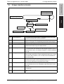
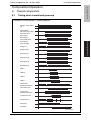
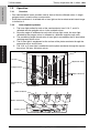
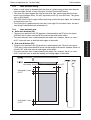
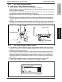
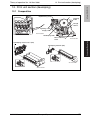
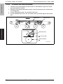
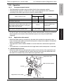
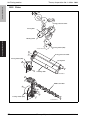
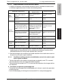
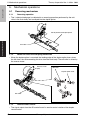
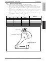
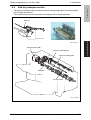
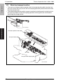
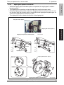
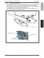
1
Color Printer d-Color P325 d-Color P330 THEORY OF OPERATION Code Y108600-3 PUBLICATION ISSUED BY: Olivetti S.p.A. 77, Via Jervis - 10015 Ivrea (TO) Italy Copyright © 2008, Olivetti All rights reserved THEORY OF OPERATION TOTAL CONTENTS SAFETY AND IMPORTANT WARNING ITEMS ..............................................................S-1 IMPORTANT NOTICE ................................................................................................S-1 DESCRIPTION ITEMS FOR DANGER, WARNING AND CAUTION .........................S-1 SAFETY WARNINGS .................................................................................................S-2 WARNING INDICATIONS ON THE MACHINE ........................................................S-18 MEASURES TO TAKE IN CASE OF AN ACCIDENT ....................................................S-21 Composition of the service manual ................................................................................. C-1 Notation of the service manual ....................................................................................... C-2 dd-Color P325/P330 main body Outline ............................................................................................................................ 1 Composition/Operation ................................................................................................... 9 Duplex option Outline ............................................................................................................................ 1 Composition/Operation ................................................................................................... 3 Lower feeder unit Outline ............................................................................................................................ 1 Composition/Operation ................................................................................................... 3 Staple finisher Outline ...........................................................................................................................1 Composition/Operation ................................................................................................... 5 Y108600-3 Theory of Operation i Blank Page ii Theory of Operation Y108600-3 SAFETY AND IMPORTANT WARNING ITEMS SAFETY AND IMPORTANT WARNING ITEMS Read carefully the safety and important warning Items described below to understand them before doing service work. IMPORTANT NOTICE Because of possible hazards to an inexperienced person servicing this product as well as the risk of damage to the product, KONICA MINOLTA BUSINESS TECHNOLOGIES, INC. (hereafter called the KMBT) strongly recommends that all servicing be performed only by KMBT-trained service technicians. Changes may have been made to this product to improve its performance after this Service Manual was printed. Accordingly, KMBT does not warrant, either explicitly or implicitly, that the information contained in this service manual is complete and accurate. The user of this service manual must assume all risks of personal injury and/or damage to the product while servicing the product for which this service manual is intended. Therefore, this service manual must be carefully read before doing service work both in the course of technical training and even after that, for performing maintenance and control of the product properly. Keep this service manual also for future service. DESCRIPTION ITEMS FOR DANGER, WARNING AND CAUTION In this service manual, each of three expressions “ DANGER”, “ WARNING”, and “ CAUTION” is defined as follows together with a symbol mark to be used in a limited meaning. When servicing the product, the relevant works (disassembling, reassembling, adjustment, repair, maintenance, etc.) need to be conducted with utmost care. DANGER: Action having a high possibility of suffering death or serious injury WARNING: Action having a possibility of suffering death or serious injury CAUTION: Action having a possibility of suffering a slight wound, medium trouble, and property damage Symbols used for safety and important warning items are defined as follows: :Precaution when servicing the product. :Prohibition when servicing the product. :Direction when servicing the product. Y108600-3 General precaution Electric hazard High temperature General prohibition Do not touch with wet hand Do not disassemble General instruction Unplug Ground/Earth Theory of Operation S-1 SAFETY AND IMPORTANT WARNING ITEMS SAFETY WARNINGS [1] MODIFICATIONS NOT AUTHORIZED BY KMBT, INC. OLIVETTI brand products are renowned for their high reliability. This reliability is achieved through high-quality design and a solid service network. Product design is a highly complicated and delicate process where numerous mechanical, physical, and electrical aspects have to be taken into consideration, with the aim of arriving at proper tolerances and safety factors. For this reason, unauthorized modifications involve a high risk of degradation in performance and safety. Such modifications are therefore strictly prohibited. the points listed below are not exhaustive, but they illustrate the reasoning behind this policy. Prohibited Actions DANGER • Using any cables or power cord not specified by KMBT. • Using any fuse or thermostat not specified by KMBT. Safety will not be assured, leading to a risk of fire and injury. • Disabling fuse functions or bridging fuse terminals with wire, metal clips, solder or similar object. • Disabling relay functions (such as wedging paper between relay contacts) • Disabling safety functions (interlocks, safety circuits, etc.) Safety will not be assured, leading to a risk of fire and injury. • Making any modification to the product unless instructed by KMBT • Using parts not specified by KMBT S-2 Theory of Operation Y108600-3 SAFETY AND IMPORTANT WARNING ITEMS [2] POWER PLUG SELECTION In some countries or areas, the power plug provided with the product may not fit wall outlet used in the area. In that case, it is obligation of customer engineer (hereafter called the CE) to attach appropriate power plug or power cord set in order to connect the product to the supply. Power Cord Set or Power Plug WARNING • Use power supply cord set which meets the following criteria: - provided with a plug having configuration intended for the connection to wall outlet appropriate for the product's rated voltage and current, and kw - the plug has pin/terminal(s) for grounding, and - provided with three-conductor cable having enough current capacity, and - the cord set meets regulatory requirements for the area. Use of inadequate cord set leads to fire or electric shock. • Attach power plug which meets the following criteria: - having configuration intended for the connection to wall outlet appropriate for the product's rated voltage and current, and - the plug has pin/terminal(s) for grounding, and - meets regulatory requirements for the area. Use of inadequate cord set leads to the product connecting to inadequate power supply (voltage, current capacity, grounding), and may result in fire or electric shock. • Conductors in the power cable must be connected to terminals of the plug according to the following order: • Black or Brown: L (line) • White or Light Blue: N (neutral) • Green/Yellow: PE (earth) Wrong connection may cancel safeguards within the product, and results in fire or electric shock. Y108600-3 Theory of Operation S-3 SAFETY AND IMPORTANT WARNING ITEMS [3] CHECKPOINTS WHEN PERFORMING ON-SITE SERVICE OLIVETTI brand products are extensively tested before shipping, to ensure that all applicable safety standards are met, in order to protect the customer and customer engineer (hereafter called the CE) from the risk of injury. However, in daily use, any electrical equipment may be subject to parts wear and eventual failure. In order to maintain safety and reliability, the CE must perform regular safety checks. 1. Power Supply Connection to Power Supply WARNING • Check that mains voltage is as specified. Connection to wrong voltage supply may result in fire or electric shock. • Connect power plug directly into wall outlet having same configuration as the plug. Use of an adapter leads to the product connecting to inadequate power supply (voltage, current capacity, grounding), and may result in fire or electric shock. kw If proper wall outlet is not available, advice the customer to contact qualified electrician for the installation. • Plug the power cord into the dedicated wall outlet with a capacity greater than the maximum power consumption. If excessive current flows in the wall outlet, fire may result. • If two or more power cords can be plugged into the wall outlet, the total load must not exceed the rating of the wall outlet. If excessive current flows in the wall outlet, fire may result. • Make sure the power cord is plugged in the wall outlet securely. Contact problems may lead to increased resistance, overheating, and the risk of fire. • Check whether the product is grounded properly. If current leakage occurs in an ungrounded product, you may suffer electric shock while operating the product. Connect power plug to grounded wall outlet. S-4 Theory of Operation Y108600-3 SAFETY AND IMPORTANT WARNING ITEMS Power Plug and Cord WARNING • When using the power cord set (inlet type) that came with this product, make sure the connector is securely inserted in the inlet of the product. When securing measure is provided, secure the cord with the fixture properly. If the power cord (inlet type) is not connected to the product securely, a contact problem may lead to increased resistance, overheating, and risk of fire. • Check whether the power cord is not stepped on or pinched by a table and so on. Overheating may occur there, leading to a risk of fire. • Check whether the power cord is damaged. Check whether the sheath is damaged. If the power plug, cord, or sheath is damaged, replace with a new power cord (with plug and connector on each end) specified by KMBT. Using the damaged power cord may result in fire or electric shock. • Do not bundle or tie the power cord. Overheating may occur there, leading to a risk of fire. • Check whether dust is collected around the power plug and wall outlet. Using the power plug and wall outlet without removing dust may result in fire. • Do not insert the power plug into the wall outlet with a wet hand. The risk of electric shock exists. • When unplugging the power cord, grasp the plug, not the cable. The cable may be broken, leading to a risk of fire and electric shock. Y108600-3 Theory of Operation S-5 SAFETY AND IMPORTANT WARNING ITEMS Wiring WARNING • Never use multi-plug adapters to plug multiple power cords in the same outlet. If used, the risk of fire exists. • When an extension cord is required, use a specified one. Current that can flow in the extension cord is limited, so using a too long extension cord may result in fire. Do not use an extension cable reel with the cable taken up. Fire may result. 2. Installation Requirements Prohibited Installation Places WARNING • Do not place the product near flammable materials or volatile materials that may catch fire. A risk of fire exists. • Do not place the product in a place exposed to water such as rain. A risk of fire and electric shock exists. When not Using the Product for a long time WARNING • When the product is not used over an extended period of time (holidays, etc.), switch it off and unplug the power cord. Dust collected around the power plug and outlet may cause fire. S-6 Theory of Operation Y108600-3 SAFETY AND IMPORTANT WARNING ITEMS Ventilation CAUTION • The product generates ozone gas during operation, but it will not be harmful to the human body. If a bad smell of ozone is present in the following cases, ventilate the room. a. When the product is used in a poorly ventilated room b. When taking a lot of copies c. When using multiple products at the same time Stability CAUTION • Be sure to lock the caster stoppers. In the case of an earthquake and so on, the product may slide, leading to a injury. Inspection before Servicing CAUTION • Before conducting an inspection, read all relevant documentation (service manual, technical notices, etc.) and proceed with the inspection following the prescribed procedure in safety clothes, using only the prescribed tools. Do not make any adjustment not described in the documentation. If the prescribed procedure or tool is not used, the product may break and a risk of injury or fire exists. • Before conducting an inspection, be sure to disconnect the power plugs from the product and options. When the power plug is inserted in the wall outlet, some units are still powered even if the POWER switch is turned OFF. A risk of electric shock exists. • The area around the fixing unit is hot. You may get burnt. Y108600-3 Theory of Operation S-7 SAFETY AND IMPORTANT WARNING ITEMS Work Performed with the Product Powered On WARNING • Take every care when making adjustments or performing an operation check with the product powered. If you make adjustments or perform an operation check with the external cover detached, you may touch live or high-voltage parts or you may be caught in moving gears or the timing belt, leading to a risk of injury. • Take every care when servicing with the external cover detached. High-voltage exists around the drum unit. A risk of electric shock exists. Safety Checkpoints WARNING • Check the exterior and frame for edges, burrs, and other damage. The user or CE may be injured. • Do not allow any metal parts such as clips, staples, and screws to fall into the product. They can short internal circuits and cause electric shock or fire. • Check wiring for squeezing and any other damage. Current can leak, leading to a risk of electric shock or fire. • Carefully remove all toner remnants and dust from electrical parts and electrode units such as a charging corona unit. Current can leak, leading to a risk of product trouble or fire. • Check high-voltage cables and sheaths for any damage. Current can leak, leading to a risk of electric shock or fire. S-8 Theory of Operation Y108600-3 SAFETY AND IMPORTANT WARNING ITEMS Safety Checkpoints WARNING • Check electrode units such as a charging corona unit for deterioration and sign of leakage. Current can leak, leading to a risk of trouble or fire. • Before disassembling or adjusting the write unit (P/H unit) incorporating a laser, make sure that the power cord has been disconnected. The laser light can enter your eye, leading to a risk of loss of eyesight. • Do not remove the cover of the write unit. Do not supply power with the write unit shifted from the specified mounting position. The laser light can enter your eye, leading to a risk of loss of eyesight. • When replacing a lithium battery, replace it with a new lithium battery specified in the Parts Guide Manual. Dispose of the used lithium battery using the method specified by local authority. Improper replacement can cause explosion. • After replacing a part to which AC voltage is applied (e.g., optical lamp and fixing lamp), be sure to check the installation state. A risk of fire exists. • Check the interlock switch and actuator for loosening and check whether the interlock functions properly. If the interlock does not function, you may receive an electric shock or be injured when you insert your hand in the product (e.g., for clearing paper jam). • Make sure the wiring cannot come into contact with sharp edges, burrs, or other pointed parts. Current can leak, leading to a risk of electric shock or fire. Y108600-3 Theory of Operation S-9 SAFETY AND IMPORTANT WARNING ITEMS Safety Checkpoints WARNING • Make sure that all screws, components, wiring, connectors, etc. that were removed for safety check and maintenance have been reinstalled in the original location. (Pay special attention to forgotten connectors, pinched cables, forgotten screws, etc.) A risk of product trouble, electric shock, and fire exists. Handling of Consumables WARNING • Toner and developer are not harmful substances, but care must be taken not to breathe excessive amounts or let the substances come into contact with eyes, etc. It may be stimulative. If the substances get in the eye, rinse with plenty of water immediately. When symptoms are noticeable, consult a physician. • Never throw the used cartridge and toner into fire. You may be burned due to dust explosion. Handling of Service Materials CAUTION • Unplug the power cord from the wall outlet. Drum cleaner (isopropyl alcohol) and roller cleaner (acetone-based) are highly flammable and must be handled with care. A risk of fire exists. • Do not replace the cover or turn the product ON before any solvent remnants on the cleaned parts have fully evaporated. A risk of fire exists. S-10 Theory of Operation Y108600-3 SAFETY AND IMPORTANT WARNING ITEMS Handling of Service Materials CAUTION • Use only a small amount of cleaner at a time and take care not to spill any liquid. If this happens, immediately wipe it off. A risk of fire exists. • When using any solvent, ventilate the room well. Breathing large quantities of organic solvents can lead to discomfort. Y108600-3 Theory of Operation S-11 SAFETY AND IMPORTANT WARNING ITEMS [4] Used Batteries Precautions ALL Areas CAUTION Danger of explosion if battery is incorrectly replaced. Replace only with the same or equivalent type recommended by the manufacturer. Dispose of used batteries according to the manufacturer’s instructions. Germany VORSICHT! Explosionsgefahr bei unsachgemäßem Austausch der Batterie. Ersatz nur durch denselben oder einen vom Hersteller empfohlenen gleichwertigen Typ. Entsorgung gebrauchter Batterien nach Angaben des Herstellers. France ATTENTION Il y a danger d’explosion s’il y a remplacement incorrect de la batterie. Remplacer uniquement avec une batterie du même type ou d’un type équivalent recommandé par le constructeur. Mettre au rebut les batteries usagées conformément aux instructions du fabricant. Denmark ADVARSEL! Lithiumbatteri - Eksplosionsfare ved fejlagtig håndtering. Udskiftning må kun ske med batteri af samme fabrikat og type. Levér det brugte batteri tilbage til leverandøren. Finland, Sweden VAROlTUS Paristo voi räjähtää, jos se on virheellisesti asennettu. Vaihda paristo ainoastaan laitevalmistajan suosittelemaan tyyppiin. Hävitä käytetty paristo valmistajan ohjeiden mukaisesti. VARNING Explosionsfara vid felaktigt batteribyte. Använd samma batterityp eller en ekvivalent typ som rekommenderas av apparattillverkaren. Kassera använt batteri enligt fabrikantens instruktion. Norway ADVARSEL Eksplosjonsfare ved feilaktig skifte av batteri. Benytt samme batteritype eller en tilsvarende type anbefalt av apparatfabrikanten. Brukte batterier kasseres i henhold til fabrikantens instruksjoner. S-12 Theory of Operation Y108600-3 SAFETY AND IMPORTANT WARNING ITEMS [5] Laser Safety • This is a digital machine certified as a Class 1 laser product. There is no possibility of danger from a laser, provided the machine is serviced according to the instruction in this manual. 5.1 Internal Laser Radiation semiconductor laser Maximum power of the laser diode 15 mW Maximum average radiation power (*) 8.5 µW Wavelength 770-800 nm *at laser aperture of the Print Head Unit • This product employs a Class 3B laser diode that emits an invisible laser beam. The laser diode and the scanning polygon mirror are incorporated in the print head unit. • The print head unit is NOT A FIELD SERVICEABLE ITEM. Therefore, the print head unit should not be opened under any circumstances. Laser Aperture of the Print Head Unit A011P0C501DA Y108600-3 Theory of Operation S-13 SAFETY AND IMPORTANT WARNING ITEMS U.S.A., Canada (CDRH Regulation) • This machine is certified as a Class 1 Laser product under Radiation Performance Standard according to the Food, Drug and Cosmetic Act of 1990. Compliance is mandatory for Laser products marketed in the United States and is reported to the Center for Devices and Radiological Health (CDRH) of the U.S. Food and Drug Administration of the U.S. Department of Health and Human Services (DHHS). This means that the device does not produce hazardous laser radiation. • The label shown on page S-16 indicates compliance with the CDRH regulations and must be attached to laser products marketed in the United States. . CAUTION • Use of controls, adjustments or performance of procedures other than those specified in this manual may result in hazardous radiation exposure. semiconductor laser Maximum power of the laser diode 15 mW Wavelength 770-800 nm All Areas CAUTION • Use of controls, adjustments or performance of procedures other than those specified in this manual may result in hazardous radiation exposure. semiconductor laser Maximum power of the laser diode 15 mW Wavelength 770-800 nm Denmark ADVARSEL • Usynlig laserstråling ved åbning, når sikkerhedsafbrydere er ude af funktion. Undgå udsættelse for stråling. Klasse 1 laser produkt der opfylder IEC60825-1 sikkerheds kravene. halvlederlaser S-14 Laserdiodens højeste styrke 15 mW bølgelængden 770-800 nm Theory of Operation Y108600-3 SAFETY AND IMPORTANT WARNING ITEMS Finland, Sweden LUOKAN 1 LASERLAITE KLASS 1 LASER APPARAT VAROITUS! • Laitteen käyttäminen muulla kuin tässä käyttöohjeessa mainitulla tavalla saattaa altistaa käyttäjän turvallisuusluokan 1 ylittävälle näkymättömälle lasersäteilylle. puolijohdelaser Laserdiodin suurin teho 15 mW aallonpituus 770-800 nm VARNING! • Om apparaten används på annat sätt än i denna bruksanvisning specificerats, kan användaren utsättas för osynlig laserstrålning, som överskrider gränsen för laserklass 1. halvledarlaser Den maximala effekten för laserdioden 15 mW våglängden 770-800 nm VARO! • Avattaessa ja suojalukitus ohitettaessa olet alttiina näkymättomälle lasersäteilylle. Älä katso säteeseen. VARNING! • Osynlig laserstråining när denna del är öppnad och spärren är urkopplad. Betrakta ej stråien. Norway ADVERSEL • Dersom apparatet brukes på annen måte enn spesifisert i denne bruksanvisning, kan brukeren utsettes för unsynlig laserstrålning, som overskrider grensen for laser klass 1. halvleder laser Y108600-3 Maksimal effekt till laserdiode 15 mW bølgelengde 770-800 nm Theory of Operation S-15 SAFETY AND IMPORTANT WARNING ITEMS 5.2 Laser Safety Label • A laser safety label is attached to the inside of the machine as shown below. A011P0E504DA 5.3 Laser Caution Label • A laser caution label is attached to the outside of the machine as shown below. A011P0C503DA S-16 Theory of Operation Y108600-3 SAFETY AND IMPORTANT WARNING ITEMS 5.4 PRECAUTIONS FOR HANDLING THE LASER EQUIPMENT • When laser protective goggles are to be used, select ones with a lens conforming to the above specifications. • When a disassembly job needs to be performed in the laser beam path, such as when working around the printerhead and PC Drum, be sure first to turn the printer OFF. • If the job requires that the printer be left ON, take off your watch and ring and wear laser protective goggles. • A highly reflective tool can be dangerous if it is brought into the laser beam path. Use utmost care when handling tools on the user’s premises. • The Print Head is not to be disassembled or adjusted in the field. Replace the Unit or Assembly including the Control Board. Therefore, remove the Laser Diode, and do not perform Control Board trimmer adjustment. Y108600-3 Theory of Operation S-17 SAFETY AND IMPORTANT WARNING ITEMS WARNING INDICATIONS ON THE MACHINE Caution labels shown are attached in some areas on/in the machine. When accessing these areas for maintenance, repair, or adjustment, special care should be taken to avoid burns and electric shock. High voltage • This area generates high voltage. Be careful not to touch here when the power is turned ON to avoid getting an electric shock. CAUTION • The area around the Fusing Unit is extremely hot. Touching any part other than those indicated may result in burns. A011P0C505DA S-18 Theory of Operation Y108600-3 SAFETY AND IMPORTANT WARNING ITEMS High voltage • This area generates high voltage. Be careful not to touch here when the power is turned ON to avoid getting an electric shock. High voltage • This area generates high voltage. Be careful not to touch here when the power is turned ON to avoid getting an electric shock. A011P0C506DA Y108600-3 Theory of Operation S-19 SAFETY AND IMPORTANT WARNING ITEMS U P H S Y WARNING • Do not burn used Imaging Units. Toner expelled from the fire is dangerous. WARNING • Do not burn used Waste Toner Bottle. Toner expelled from the fire is dangerous. Y WARNING • Do not burn used Toner Cartridge. Toner expelled from the fire is dangerous. A011P0C507DA CAUTION: • You may be burned or injured if you touch any area that you are advised not to touch by any caution label. Do not remove caution labels. If any caution label has come off or soiled and therefore the caution cannot be read, contact our Service Office. S-20 Theory of Operation Y108600-3 MEASURES TO TAKE IN CASE OF AN ACCIDENT MEASURES TO TAKE IN CASE OF AN ACCIDENT 1. If an accident has occurred, the distributor who has been notified first must immediately take emergency measures to provide relief to affected persons and to prevent further damage. 2. If a report of a serious accident has been received from a customer, an on-site evaluation must be carried out quickly and KMBT must be notified. 3. To determine the cause of the accident, conditions and materials must be recorded through direct on-site checks, in accordance with instructions issued by KMBT. 4. For reports and measures concerning serious accidents, follow the regulations specified by every distributor. Y108600-3 Theory of Operation S-21 MEASURES TO TAKE IN CASE OF AN ACCIDENT Blank Page S-22 Theory of Operation Y108600-3 Composition of the service manual This service manual consists of Theory of Operation section and Field Service section to explain the main machine and its corresponding options. Theory of Operation section gives, as information for the CE to get a full understanding of the product, a rough outline of the object and role of each function, the relationship between the electrical system and the mechanical system, and the timing of operation of each part. Field Service section gives, as information required by the CE at the site (or at the customer’s premise), a rough outline of the service schedule and its details, maintenance steps, the object and role of each adjustment, error codes and supplementary information. The basic configuration of each section is as follows. However some options may not be applied to the following configuration. <Theory of Operation section> OUTLINE: Explanation of system configuration, product specifications, unit configuration, and paper path COMPOSITION/OPERATION: Explanation of configuration of each unit, operating system, and control system <Field Service section> GENERAL: Explanation of system configuration, and product specifications MAINTENANCE: Explanation of service schedule, maintenance steps, service tools, removal/reinstallation methods of major parts, and firmware version up method etc. ADJUSTMENT/SETTING: Explanation of utility mode, service mode, and mechanical adjustment etc. TROUBLESHOOTING: Explanation of lists of jam codes and error codes, and their countermeasures etc. APPENDIX: Parts layout drawings, connector layout drawings, timing chart, overall layout drawing are attached. Y108600-3 Theory of Operation C-1 Notation of the service manual A. Product name In this manual, each of the products is described as follows: (1) PCRB: Print control board (2) d-Color P325/P330: Main body (3) Microsoft Windows 95: Windows 95 Microsoft Windows 98: Windows 98 Microsoft Windows Me: Windows Me Microsoft Windows NT 4.0: Windows NT 4.0 or Windows NT Microsoft Windows 2000: Windows 2000 Microsoft Windows XP: Windows XP When the description is made in combination of the OS’s mentioned above: Windows 95/98/Me Windows NT 4.0/2000 Windows NT/2000/XP Windows 95/98/Me/ NT/2000/XP B. Brand name The company names and product names mentioned in this manual are the brand name or the registered trademark of each company. C. Feeding direction • When the long side of the paper is parallel with the feeding direction, it is called short edge feeding. The feeding direction which is perpendicular to the short edge feeding is called the long edge feeding. • Short edge feeding will be identified with [S (abbreviation for Short edge feeding)] on the paper size. No specific notation is added for the long edge feeding. When the size has only the short edge feeding with no long edge feeding, [S] will not be added to the paper size. <Sample notation> Paper size A4 A3 C-2 Feeding direction Notation Long edge feeding A4 Short edge feeding A4S Short edge feeding A3 Theory of Operation Y108600-3 Color Printer d-Color P325 d-Color P330 THEORY OF OPERATION Code Y108600-3 Revision history After publication of this service manual, the parts and mechanism may be subject to change for improvement of their performance. Therefore, the descriptions given in this service manual may not coincide with the actual machine. When any change has been made to the descriptions in the service manual, a revised version will be issued with a revision mark added as required. Revision mark: • To indicate clearly a section revised, show 1 to the left of the revised section. A number within 1 represents the number of times the revision has been made. • To indicate clearly a section revised, show 1 in the lower outside section of the corresponding page. A number within 1 represents the number of times the revision has been made. NOTE Revision marks shown in a page are restricted only to the latest ones with the old ones deleted. • When a page revised in Ver. 2.0 has been changed in Ver. 3.0: The revision marks for Ver. 3.0 only are shown with those for Ver. 2.0 deleted. • When a page revised in Ver. 2.0 has not been changed in Ver. 3.0: The revision marks for Ver. 2.0 are left as they are. Theory of operation Ver. 1.0 Nov. 2006 d-Color P325/P330 main body Outline 1. System configuration............................................................................................... 1 2. Product specifications ............................................................................................. 2 3. Section configuration............................................................................................... 5 4. Media path .............................................................................................................. 6 5. Image creation process........................................................................................... 7 Outline d-Color P325/P330 CONTENTS 6. Overall composition................................................................................................. 9 6.1 Timing chart at main body powerup ..................................................................... 9 6.2 Control block diagram ......................................................................................... 10 7. Write section ......................................................................................................... 11 7.1 Composition........................................................................................................ 11 7.2 Operation ............................................................................................................ 12 7.2.1 Overview ..................................................................................................... 12 7.2.2 Laser exposure process.............................................................................. 12 7.2.3 Laser emission timing ................................................................................. 13 7.2.4 Laser emission area.................................................................................... 13 7.2.5 Laser light intensity control ......................................................................... 14 7.2.6 Registration correction control .................................................................... 14 8. Toner supply section ............................................................................................. 15 8.1 Composition........................................................................................................ 15 8.2 Drive ................................................................................................................... 16 8.3 Operation ............................................................................................................ 17 9. 8.3.1 Toner cartridge capacity.............................................................................. 17 8.3.2 Toner conveying mechanism....................................................................... 17 8.3.3 Toner collecting port shutter mechanism .................................................... 18 8.3.4 Toner replenishing mechanism ................................................................... 19 8.3.5 Toner level detection ................................................................................... 20 8.3.6 Toner near-empty condition detection ......................................................... 20 8.3.7 Toner empty condition detection ................................................................. 21 8.3.8 Toner empty condition detection control ..................................................... 21 8.3.9 Toner cartridge life control........................................................................... 22 Print unit section (overall composition).................................................................. 23 Y108600-3 Theory of Operation i Composition/Operation Composition/Operation d-Color P325/P330 Theory of operation Ver. 1.0 Nov. 2006 9.1 Composition ....................................................................................................... 23 9.2 Operation............................................................................................................ 24 10. 9.2.1 Print unit life detection ................................................................................ 24 9.2.2 Print unit life control .................................................................................... 24 Print unit section (photo conductor) ...................................................................... 25 10.1 Composition ....................................................................................................... 25 10.2 Drive ................................................................................................................... 25 Outline 10.3 Operation............................................................................................................ 26 Composition/Operation 11. 10.3.1 Photo conductor drive mechanism ............................................................. 26 10.3.2 Photo conductor post-exposure control ...................................................... 27 10.3.3 Photo conductor total exposure control upon recovery............................... 27 10.3.4 Photo conductor small amount rotation control .......................................... 27 Print unit section (charge corona) ......................................................................... 28 11.1 Composition ....................................................................................................... 28 11.2 Operation............................................................................................................ 29 12. 11.2.1 Charge corona unit ON/OFF control........................................................... 29 11.2.2 Output during pre-process .......................................................................... 29 11.2.3 Output during post-process ........................................................................ 29 11.2.4 Ozone ventilation mechanism..................................................................... 30 Print unit section (developing)............................................................................... 31 12.1 Composition ....................................................................................................... 31 12.2 Operation............................................................................................................ 32 13. 12.2.1 Developing drive control ............................................................................. 32 12.2.2 Toner collecting port shutter mechanism .................................................... 33 12.2.3 Toner flow ................................................................................................... 34 12.2.4 Developing system...................................................................................... 35 12.2.5 Cleaning mechanism .................................................................................. 36 12.2.6 Toner collecting port shutter mechanism .................................................... 36 Transfer section (1st transfer)................................................................................ 37 13.1 Composition ....................................................................................................... 37 13.2 Drive ................................................................................................................... 38 13.3 Operation............................................................................................................ 39 ii 13.3.1 1st transfer output control ........................................................................... 39 13.3.2 1st transfer roller pressure/retraction control .............................................. 39 13.3.3 1st transfer roller pressure operation .......................................................... 40 13.3.4 1st transfer roller retraction operation ......................................................... 41 13.3.5 1st transfer roller pressure/retraction position control................................. 42 13.3.6 Transfer belt cleaning mechanism .............................................................. 43 13.3.7 1st transfer belt cleaning control ................................................................. 44 Theory of Operation Y108600-3 14. 13.3.8 1st transfer belt backward rotation control .................................................. 44 13.3.9 Toner collecting port shutter mechanism .................................................... 45 Transfer section (2nd transfer)............................................................................... 46 14.1 Composition........................................................................................................ 46 14.2 Drive ................................................................................................................... 47 d-Color P325/P330 Theory of operation Ver. 1.0 Nov. 2006 15. 14.3.1 2nd transfer roller pressure mechanism...................................................... 47 14.3.2 2nd transfer roller pressure position deviation preventive mechanism........ 49 14.3.3 2nd transfer voltage control......................................................................... 50 14.3.4 2nd transfer voltage setting control (ATVC: auto transfer voltage control) .. 50 14.3.5 2nd transfer roller cleaning control.............................................................. 51 Outline 14.3 Operation ............................................................................................................ 47 Waste toner collecting section............................................................................... 52 15.2 Drive ................................................................................................................... 53 15.3 Operation ............................................................................................................ 54 15.3.1 Waste toner collecting mechanism at the 1st transfer section .................... 54 15.3.2 Toner flow at the 2nd transfer section ......................................................... 55 15.3.3 Toner collecting port shutter mechanism at the suction transport unit........ 56 15.3.4 Toner collecting port shutter mechanism of the waste toner bottle ............. 56 15.3.5 Waste Toner Box locking mechanism ......................................................... 57 15.3.6 Waste toner box locked position detection mechanism .............................. 57 15.3.7 Waste toner box-in-position detection mechanism...................................... 58 15.3.8 Waste toner flow in the waste toner box ..................................................... 58 15.3.9 Waste toner near-full condition detection control ........................................ 59 15.3.10 Waste toner full condition detection control ................................................ 59 16. Media feed section (Tray 1) ................................................................................... 60 16.1 Composition........................................................................................................ 60 16.2 Drive ................................................................................................................... 61 16.3 Operation ............................................................................................................ 61 17. 16.3.1 Media lift plate mechanism ......................................................................... 61 16.3.2 Media separation mechanism ..................................................................... 62 16.3.3 Media feed control....................................................................................... 62 16.3.4 Media empty condition detection control..................................................... 63 16.3.5 Edge guide plate ......................................................................................... 64 16.3.6 Media misfeed detection control ................................................................. 64 Media feed section (Tray 2) ................................................................................... 65 17.1 Composition........................................................................................................ 65 17.2 Drive ................................................................................................................... 66 Y108600-3 Theory of Operation iii Composition/Operation 15.1 Composition........................................................................................................ 52 Theory of operation Ver. 1.0 Nov. 2006 Outline d-Color P325/P330 17.3 Operation............................................................................................................ 66 18. 17.3.1 Media lift plate mechanism ......................................................................... 66 17.3.2 Media separation mechanism..................................................................... 67 17.3.3 Media feed control ...................................................................................... 67 17.3.4 Media supply level detection control ........................................................... 68 17.3.5 Media empty condition detection control .................................................... 68 17.3.6 Edge guide plate......................................................................................... 69 17.3.7 Trailing edge guide plate............................................................................. 69 17.3.8 Tray open/close detection control ............................................................... 70 17.3.9 Media misfeed detection control ................................................................. 70 Conveyance section (IDC sensor)......................................................................... 71 18.1 Composition ....................................................................................................... 71 Composition/Operation 18.1.1 Drive ........................................................................................................... 72 18.2 Operation............................................................................................................ 72 19. 18.2.1 Toner density detection control ................................................................... 72 18.2.2 IDC sensor calibration control..................................................................... 73 18.2.3 IDC sensor shutter mechanism .................................................................. 73 Conveyance section (Registration roller) .............................................................. 74 19.1 Composition ....................................................................................................... 74 19.2 Drive ................................................................................................................... 74 19.3 Operation............................................................................................................ 75 19.3.1 Conveyance speed control ......................................................................... 75 19.3.2 Registration roller control............................................................................ 75 19.3.3 Control of loop formed before registration roller ......................................... 76 19.3.4 Control of loop formed before 2nd transfer ................................................. 77 19.3.5 Control of loop formed before fusing section .............................................. 78 19.3.6 Media neutralization.................................................................................... 79 19.3.7 OHP transparencies detection control ........................................................ 80 19.3.8 Media size error detection control............................................................... 81 19.3.9 Conveyance system media misfeed detection control ................................ 82 19.3.10 Remaining media detection control when the main power switch is turned ON ............................................................................................... 84 19.3.11 Temperature/humidity sensor ..................................................................... 84 20. Fusing section....................................................................................................... 85 20.1 Composition ....................................................................................................... 85 20.2 Drive ................................................................................................................... 86 20.3 Operation............................................................................................................ 87 iv 20.3.1 Fusing pressure roller pressure selection mechanism ............................... 87 20.3.2 Fusing pressure roller drive control ............................................................ 88 Theory of Operation Y108600-3 20.3.3 Fusing temperature control ......................................................................... 93 20.3.4 Fusing temperature control management ................................................... 94 20.3.5 Warm-up control.......................................................................................... 95 20.3.6 Post-warm-up control .................................................................................. 97 20.3.7 Wait control ................................................................................................. 97 20.3.8 Proactive control ......................................................................................... 98 20.3.9 Print control................................................................................................. 98 d-Color P325/P330 Theory of operation Ver. 1.0 Nov. 2006 20.3.11 Heater OFF control ..................................................................................... 99 20.3.12 PPM control .............................................................................................. 100 Outline 20.3.10 Post-print control ......................................................................................... 99 20.3.13 Protection against abnormally high temperature ...................................... 101 21. Image stabilization control................................................................................... 103 22. 21.1.1 Complete correction control ...................................................................... 103 21.1.2 Simplified correction control ...................................................................... 104 21.1.3 Individual registration control .................................................................... 104 21.1.4 Image stabilization control execution request ........................................... 105 21.1.5 Conditions enabling execution of stabilization control at the end of a print cycle of given conditions ........................................... 105 21.1.6 Combination and execution sequence of different sub-controls................ 106 Miscellaneous ..................................................................................................... 107 22.1 Fan control ........................................................................................................ 107 22.1.1 Composition .............................................................................................. 107 22.1.2 Function .................................................................................................... 107 22.1.3 Control ...................................................................................................... 108 Y108600-3 Theory of Operation v Composition/Operation 21.1 Overview of image stabilization control ............................................................ 103 Composition/Operation Outline d-Color P325/P330 Theory of operation Ver. 1.0 Nov. 2006 Blank Page vi Theory of Operation Y108600-3 Theory of operation Ver. 1.0 Nov. 2006 1. System configuration 1. d-Color P325/P330 Outline System configuration System front view [1] Outline [2] [6] [3] [5] [4] A011F1C501DA [1] Main body [4] Lower feeder unit [2] Duplex option [5] Lower feeder unit [3] Hard disk kit [6] Staple finisher Y108600-3 Theory of Operation 1 2. Product specifications d-Color P325/P330 2. Theory of operation Ver. 1.0 Nov. 2006 Product specifications Outline A. Type Type Desktop tandem full-color laser beam printer Printing system Semiconductor laser and electrostatic image transfer to media Exposure system 4 laser diode and polygon mirror PC drum type OPC (organic photo conductor) Photoconductor cleaning Blade cleaning system Print resolution 600 dpi x 600 dpi x 4 bit Media feeding system Two-way system (Tray 1: 100 sheets, Tray 2: 500 sheets) * Expandable up to a four-way system by adding lower feeder units (up to two) Developing system Single-element developing system Charging system Needle charging system (with ozone suctionfeature) Image transfer system Intermediate transfer belt system Media separating system Curvature separation + charge-neutralizing system Fusing system Belt fusing Media exit system Face down (Output tray capacity: A4S/Letter, 250 sheets) B. Functions Warm-up time Process speed Average: 45 sec. or less (Power on to ready, at ambient temperature of 23° C/73.4° F and rated source voltage) d-Color P325 152 mm/sec (plain paper, full-color mode) d-Color P330 185 mm/sec (plain paper, full-color mode) First-page-out-time d-Color P325 14.2 second (Full-color mode, A4S/Letter, 1-sided mode, plain paper) d-Color P330 14.0 second (Full-color mode, A4S/Letter, 1-sided mode, plain paper) Print speed d-Color P330 Full-color mode : 27.0 pages/min. (Letter, 1-sided print, plain paper) 25.6 pages/min. (A4S, 1-sided print, plain paper) Monochrome mode : 31.7 pages/min. (Letter, 1-sided print, plain paper) 30.0 pages/min. (A4S, 1-sided print, plain paper) d-Color P330 Full-color mode : 31.7 pages/min. (Letter, 1-sided print, plain paper) 30.0 pages/min. (A4S, 1-sided print, plain paper) Monochrome mode : 37.0 pages/min. (Letter, 1-sided print, plain paper) 35.0 pages/min. (A4S, 1-sided print, plain paper) 2 Theory of Operation Y108600-3 Theory of operation Ver. 1.0 Nov. 2006 d-Color P325/P330 Tray 1 Standard size: *SEF only • Legal, Letter, Government Letter, Statement, Executive, Folio, SP Folio, UK Quatro, Foolscap, Government, Legal • A4S, B5, B5(ISO), A5, A6, B6, Photo size • 16K, Kai16, Kai32 Envelope: • Com10, C5, C6, DL, Monarch • Youkei #4, Youkei 4, Choukei #3, Youkei 0, Choukei #4 Postcard: • Japanese postcard, Double postcard Custom size: • Minimum size /92 mm x 148 mm (3.6 inch x 5.8 inch) • Maximum size /218 mm x 356 mm (8.6 inch x 14.0 inch) • Long size paper /357 mm to 1,200 mm (14.0 inch x 47.2 inch) (1-sided mode only) Outline Media sizes 2. Product specifications Tray 2 A4S/LetterS Media types Tray 1 • Plain paper (60 to 90 g/m2 / 16 to 24 lb) • Recycled paper (60 to 90 g/m2 / 16 to 24 lb) • Thick stock 1 (91 to 150 g/m2/ 24 to 40 lb) • Thick stock 2 (128 to 210 g/m2/ 34 to 56 lb) • Glossy paper 1 (100 to 150 g/m2/ 26.6 to 40 lb) • Glossy paper 2 (128 to 210 g/m2/ 34 to 56 lb) • OHP transparencies • Letterhead • Envelopes • Labels • Postcards • Double postcards *1 • Long size paper (up to 1200 mm/47.2 inches) Tray 2 • Plain paper (60 to 90 g/m2 / 16 to 24 lb) • Recycled paper (60 to 90 g/m2 / 16 to 24 lb) Tray capacities Tray 1 Plain paper and recycled paper: 100 sheets Thick stock 1, thick stock 2,glossy paper 1, glossy paper 2, postcards, OHP transparencies, letterhead, labels, postcards and double postcards: 20 sheets Envelopes: 10 sheets Long size paper: 1 sheet * No indication of remaining media amount Tray 2 Plain paper and recycled paper: 500 sheets * Indication of remaining madia amount available Interfaces • • • • Parallel (IEEE 1284) Support only an ECP mode 10 Base-T/100 Base-TX/1000 Base-T (IEEE 802.3) Ethernet USB 2.0 (High-Speed) Host USB (PictBridge 1.0) CPU d-Color P325 Freescale PowerPC 7448, 733 MHz d-Color P330 Freescale PowerPC 7448, 866 MHz Y108600-3 Theory of Operation 3 d-Color P325/P330 2. Product specifications Theory of operation Ver. 1.0 Nov. 2006 Memory Standard memory DDR-SDRAM 133 MHz 184 pin non ECC 256 MB (Expandable up to a 1024 MB) Hard disk Optional: 40 GB Compact flash card Commercially available compact flash cards of 256 MB, 512 MB, 1 GB or more storage capacity are supported. (Microdrive is not supported) *1: Folded double postcards cannot be used. Outline Lower feeder unit: Only plain paper and recycled paper weighing 60 to 90 g/m2 (16 to 24 lb) can be loaded. Duplex option: Only plain paper and recycled paper weighing 60 to 90 g/m2 (16 to 24 lb) can be fed through the unit. For details, see the Service Manual for each option. C. Maintenance Machine durability 400,000 prints or 5 years, whichever comes first D. Machine specifications Power requirements AC 110 to 127 V, -10% +6% ( AC 120 V -10% +10% : onry US / Canada) Voltage: AC 220 to 240 V, -10% +10% Frequency: 50 to 60 Hz ± 3 Hz Max power consumption 1400 W or less Dimensions 420 mm (W) x 526 mm (D) x 420 mm (H) 16.5 inch (W) x 20.7 inch (D) x 16.5 inch (H) Weight 32.4 kg (71.4 lb) or less without consumables Operating noise During standby : 39 dB (A) or less During printing : 56 dB (A) or less E. Operating Environment Temperature 10° to 35° C / 50° to 95° F (with a fluctuation of 10° C / 18° F or less per hour) Humidity 15% to 85% (with a fluctuation of 20%/h) NOTE • These specifications are subject to change without notice. 4 Theory of Operation Y108600-3 Theory of operation Ver. 1.0 Nov. 2006 Section configuration Toner supply section d-Color P325/P330 3. 3. Section configuration Fusing section Outline Transfer section Conveyance section Waste toner collecting section Media feed section (Tray 1) Write section Media feed section (Tray 2) A011T1C500AA Print unit section Y108600-3 Theory of Operation 5 4. Media path Media path Outline d-Color P325/P330 4. Theory of operation Ver. 1.0 Nov. 2006 A011T1C001DA 1-sided media path 2-sided media path 1-sided media path from the tray 1 6 Theory of Operation Y108600-3 Theory of operation Ver. 1.0 Nov. 2006 Image creation process d-Color P325/P330 5. 5. Image creation process [8] Media separation [7] 2nd image transfer [9] Transfer belt cleaning [2] PC drum Outline [6] 1st image transfer [10] PC drum cleaning [5] Developing [3] PC drum charging [1] Printer processing [4] LD exposure [1] Printer processing • The intensity of the laser light is controlled based on the image signal transmitted from the host computer. [2] PC drum • The image of the original projected onto the surface of the PC drum is changed to a corresponding electrostatic latent image. [3] PC drum charging • Apply DC (-) charge to the photo conductor. [4] LD exposure • The surface of the PC drum is irradiated with laser light, and an electrostatic latent image is thereby formed. [5] Developing • The toner, agitated and negatively charged in the toner chamber, is attracted onto the electrostatic latent image formed on the surface of the PC drum. It is thereby changed to a visible, developed image. [6] 1st image transfer • A DC positive voltage is applied to the backside of the transfer belt, thereby allowing the visible, developed image on the surface of each of the PC drums (Y, M, C and K) to be transferred onto the transfer belt. [7] 2nd image transfer • A DC positive voltage is applied to the backside of the media, thereby allowing the visible, developed image on the surface of the transfer belt to be transferred onto the media. [8] Media separation • The media, which has undergone the 2nd image transfer process, is neutralized so that it can be properly separated from the transfer belt. [9] Transfer belt cleaning • The residual toner left on the surface of the transfer belt is scraped off. [10] PC drum cleaning • The residual toner left on the surface of the PC drum is scraped off. Y108600-3 Theory of Operation 7 Theory of operation Ver. 1.0 Nov. 2006 Outline d-Color P325/P330 5. Image creation process Blank Page 8 Theory of Operation Y108600-3 Theory of operation Ver. 1.0 Nov. 2006 6. Overall composition 6. 6.1 d-Color P325/P330 Composition/Operation Overall composition Timing chart at main body powerup Conditions: A4S plain paper, 2 printed pages/job Polygon motor (M8) LD Intermediate transport motor (M3) Color PC drum motor (M2) Composition/Operation Developing motor/YMC (M1) Developing motor/K (M5) Charge K Charge YMC Developing Y Developing M Developing C Developing K TOD Y TOD M TOD C TOD K 1st transfer pressure/retraction 1st transfer rem 2nd transfer pressure/retraction 2nd transfer rem 2nd transfer (-) First page 2nd page A011T2E061DA Y108600-3 Theory of Operation 9 d-Color P325/P330 6. Overall composition 6.2 Theory of operation Ver. 1.0 Nov. 2006 Control block diagram Operation board (OB) Print control board (PRCB) MFP board (MFPB) Media feed and conveyance Image processing CPU Process Composition/Operation Fusing Leser drive board (LASDB) TC/Y TC/M TC/C TC/K PU/Y PU/M PU/C PU/K Control system line Image bus line Staple finisher Lower feeder unit Duplex unit A011T2E062DA 10 Theory of Operation Y108600-3 7. Write section 7.1 Composition 7. Write section d-Color P325/P330 Theory of operation Ver. 1.0 Nov. 2006 A011T2C500AA 4138to2001c0 G2 lens Composition/Operation Return mirror/2nd Separation mirror SOS lens Return mirror/1st Index board G1 lens Synthetic mirror Polygon mirror 4138to2002c0 Semiconductor laser Y108600-3 Theory of Operation 11 d-Color P325/P330 7. Write section 7.2 Theory of operation Ver. 1.0 Nov. 2006 Operation 7.2.1 Overview • Four semiconductor lasers provided, one for each of the four different colors. A single polygon motor is used to make a scan motion. • Each photo conductor is irradiated with a laser light so that an electrostatic latent image is formed on it. 7.2.2 Laser exposure process Composition/Operation 1. The laser light emitted by each of the semiconductor laser/Y, M, C, and K is reflected onto the polygon mirror via the synthetic mirror. 2. Since the angle of incidence for each color of laser light varies, the laser light reflected by the polygon mirror is reflected at a different angle for each color. 3. The condensing angle of each color of laser light is corrected by the G1 lens before reaching each return mirror. 4. The K laser light is condensed on the surface of the photo conductor through the separation mirror and G2 lens. 5. The Y, M, or C laser light is condensed on the photo conductor through the separation mirror, G2 lens, and return mirror. Index sensor SOS lens G1 lens Separation mirror Polygon mirror Y M Return mirror/1st C Y K M K C Semiconductor laser Synthetic mirror Photo conductor Y M C K Return mirror/2nd Y M C K G2 lens Y M C K 4138to2502c0 12 Theory of Operation Y108600-3 7.2.3 7. Write section Laser emission timing • When a ready signal is detected after the lapse of a given period of time after the print cycle has been started, a laser ON signal is output from the MFP board. • The laser ON signal triggers the firing of each laser light, which illuminates the index board via the polygon mirror, G1 lens, separation mirror (K), and SOS lens. This generates an SOS signal. • This SOS (Start of Scan) signal unifies the timing at which the laser lights are irradiated for each main scan line. • The SOS signal is generated only from the K laser light. For the other colors, the emission timing is determined with reference to K. 7.2.4 d-Color P325/P330 Theory of operation Ver. 1.0 Nov. 2006 Laser emission area B. Sub scan direction (CD) • The print start position in the CD direction is determined by the CD print start signal (TOD) that is output from the MFP board and the length of the media. However, there is a 4 mm/0.157" wide void area on both edges of the media. • The laser emission area is determined by the media size. However, there is a 4 mm/ 0.157" wide void area on both the leading and trailing edges of the media. Void width: 4 mm/0.157" Void width: 4 mm/0.157" Void width: 4 mm/ 0.157" Void width: 4 mm/ 0.157" 4138to2595c0 Y108600-3 Theory of Operation 13 Composition/Operation A. Main scan direction (FD) • The print start position in the FD direction is determined by the FD print start signal (HSYNC) that is output from the MFP board and the width of the media. • The laser emission area is determined by the media size. However, there is a 4 mm/ 0.157" wide void area on both the both edges of the media. d-Color P325/P330 7. Write section 7.2.5 Theory of operation Ver. 1.0 Nov. 2006 Laser light intensity control • The laser light intensity control corrects the target level of fluctuations in fine line reproduction and reverse image (white on black) reproduction that occur due to variations in photo conductor electrostatic characteristics, developing characteristics, and transfer characteristics (part-to-part variations, environment, durability). • It is controlled integrally with other control items by the image stabilization control. • The laser light intensity control is performed when there is a request made for execution of an image stabilization sequence. 7.2.6 Registration correction control Composition/Operation • In a tandem engine that has an image forming process for each color of toner, incorrect color registration tends to occur due to variations in parts of the main body used for regulating the drawing positions. The registration correction control automatically detects and corrects this incorrect color registration. • It is controlled integrally with other control items by the image stabilization control. • The registration correction control is performed when there is a request made for execution of image stabilization sequence. 14 Theory of Operation Y108600-3 Theory of operation Ver. 1.0 Nov. 2006 8.1 Toner supply section d-Color P325/P330 8. 8. Toner supply section Composition A011T2C501AA Composition/Operation A011T2C005DA TC detection board (CSIC) A011T2C006DA Conveyance screw Toner collecting port Agitating blade Conveyance screw Y108600-3 Theory of Operation A011T2C007DA 15 d-Color P325/P330 8. Toner supply section 8.2 Theory of operation Ver. 1.0 Nov. 2006 Drive Front view Toner supply motor/C, K (M7) Toner supply motor/Y, M (M6) 4138to2599c0 Composition/Operation 3D view Toner supply motor/C, K (M7) Toner supply motor/Y, M (M6) Agitating blade Conveyance screw 4138to2019c0 16 Theory of Operation Y108600-3 8.3 8. Toner supply section Operation 8.3.1 Toner cartridge capacity • There are three different types of toner cartridges which contain a different toner amount. • Toner cartridges shipped with main body: Quantity equivalent to 3,000 printed pages (Not equipped with TC detection board) • Standard-capacity toner cartridges: Quantity equivalent to 6,000 printed pages • High-capacity toner cartridges: Quantity equivalent to 12,000 printed pages 8.3.2 d-Color P325/P330 Theory of operation Ver. 1.0 Nov. 2006 Toner conveying mechanism Agitating blade Conveyance screw A011T2C006DA Composition/Operation • The toner supply motor is turned either forward or backward to drive the agitating blade and the conveyance screw. • The agitating blade provided in the toner cartridge agitates and conveys toner to the conveyance screw. • The toner conveyed by the agitating blade is conveyed to the toner collecting port sitting on the front side of the main body by the conveyance screw. Toner collecting port Rear side Agitating blade Conveyance screw A011T2C007DA Y108600-3 Theory of Operation A011T2C009DA 17 d-Color P325/P330 8. Toner supply section 8.3.3 Theory of operation Ver. 1.0 Nov. 2006 Toner collecting port shutter mechanism • The toner collecting port is equipped with a shutter mechanism that prevents toner from being spilled out when the toner cartridge is removed from the main body. • After installing the toner cartridge into the main body, placing the print unit release lever in its locked position opens the shutter of the toner collecting port. Then toner can be conveyed to the main body. • Moving the print unit release lever to the right or left accompanies the synchronizing movement of the slider. This makes the gear connected to the shutter rotated and then makes the shutter opened or closed. • To prevent the front door from getting closed while the shutter is open, the preventive mechanism works in the way that the front door cannot be closed by interfering with the release lever until the release lever is placed in the locked position (to the left in the picture). Composition/Operation Slider Close Open Release lever 18 Shutter A011T2C010DA Theory of Operation A011T2C011DA Y108600-3 8.3.4 8. Toner supply section Toner replenishing mechanism • The toner supply motor is energized according to the condition of the toner level sensor for each color of toner. Toner is then supplied from the toner cartridge to the print unit as necessary. • A single toner supply motor is turned either forward or backward to accomplish supply of toner of two different colors (one motor is for Y and M, and the other for C and K). That is, M (K) toner cannot be supplied while Y (C) toner is being supplied. • Toner is supplied only while the print unit is being driven. This is because of the following reason: if toner is supplied from the toner cartridge while the print unit remains stationary, toner stagnates at the print unit. Direction of rotation Toner supply (as viewed from above of motor motor shaft) /C, /K (M7) Toner supply (Agitating blade/conveyance screw) Y M C K Forward (clockwise) Turned Stationary Stationary Stationary Backward (counterclockwise) Stationary Turned Stationary Stationary Forward (clockwise) Stationary Stationary Turned Stationary Backward (counterclockwise) Stationary Stationary Stationary Turned When the motor turns forward When the motor turns backward Toner supply motor (M6) Toner supply motor (M7) Composition/Operation /Y, /M (M6) K C M Y 4138to2013c0 Y/C one-way clutch turns. Y108600-3 d-Color P325/P330 Theory of operation Ver. 1.0 Nov. 2006 Theory of Operation 4138to2014c0 M/K one-way clutch turns. 19 d-Color P325/P330 8. Toner supply section 8.3.5 Theory of operation Ver. 1.0 Nov. 2006 Toner level detection • The toner level is determined by the accumulated time of rotation of the toner supply motor. • The toner level can be checked through MENU/PRINT MENU/STATISTICS PAGE. 8.3.6 Toner near-empty condition detection • The cumulative period of time through which the toner supply motor is energized is detected as the basis for determining whether there is a toner near-empty condition. • The main body is designed to indicate a toner near-empty condition when the toner level remaining in the toner cartridge becomes approx. 40 percent. Pages that can be printed Toner level after toner near-empty (Targeted percent) detection (Targeted number of pages) * Toner cartridge Composition/Operation Toner cartridge shipped with main body: Quantity equivalent to 3000 printed pages Standard toner cartridge: Quantity equivalent to 6000 printed pages Approx. 1,200 sheets 40% High-capacity toner cartridge: Quantity equivalent to 12,000 printed Approx. 2,400 sheets Approx. 4,800 sheets * for a standard original of a 5% coverage rate • A toner near-empty condition is reset when a new toner cartridge is detected. Display example: Toner near-empty indication (Magenta) READY TONER LOW M for help YMCK 4138F3E013DA 20 Theory of Operation Y108600-3 8.3.7 8. Toner supply section Toner empty condition detection A. Toner empty condition detection mechanism • The print unit has a toner empty condition detecting mechanism. Based on the amount of toner conveyed from the toner cartridge to the print unit, a toner empty condition is detected. • A toner level in the print unit is detected by the LED and toner level sensor mounted on the toner level sensor board provided in the main body. • Light emitted from the LED travels through the light guiding path and is guided into the print unit. • The toner level sensor detects the intensity of the transmitted light guided through the light guiding path from the inside of the toner cartridge. The toner level is thereby estimated. • To ensure correct detection of the intensity of transmitted light by the toner level sensor, a cleaning sheet is provided that cleans the window in the light guiding path periodically. LED Sensor Composition/Operation Cleaning sheet Light guiding path Cleaning sheet 4138to2012c2 4138to2012c1 Print unit 8.3.8 Print unit Toner empty condition detection control • A sequence is started for detecting a toner empty condition when a toner near-empty condition is detected. (In starter cartridges shipped with a main body, the toner empty detection control always functions.) • The main body determines that there is a toner empty condition when the toner level sensor output value remains below a predetermined value and if the following event is detected a predetermined number of consecutive times: the output value of the toner level sensor remains a predetermined value or lower for more than a predetermined period of time. • The consecutive detection count is retained even when power is turned OFF. • A toner empty condition is reset when a new toner cartridge is detected. Display example: Toner empty indication (Magenta) TONER EMPTY REPLACE M for help YMCK 4138F3E004DA Y108600-3 d-Color P325/P330 Theory of operation Ver. 1.0 Nov. 2006 Theory of Operation 21 8.3.9 Theory of operation Ver. 1.0 Nov. 2006 Toner cartridge life control • Each toner cartridge is provided with a TC detection board that detects state of a toner cartridge placement, a new TC, a toner near-empty condition, and a toner empty condition. Composition/Operation d-Color P325/P330 8. Toner supply section 22 Theory of Operation Y108600-3 Theory of operation Ver. 1.0 Nov. 2006 9.1 Print unit section (overall composition) d-Color P325/P330 9. 9. Print unit section (overall composition) Composition A011T2C508AA PC motor Composition/Operation A011T2C012DA PU detection board (CSIC) Developing motor A011T2C013DA Photo conductor Replenishing screw Cleaning blade Agitating screw Supply roller Charge corona Developing roller Toner collecting screw A011T2C014DA Y108600-3 Theory of Operation 23 9.2 9.2.1 Theory of operation Ver. 1.0 Nov. 2006 Operation Print unit life detection • Based on the photo conductor driving time, the cartridge life is determined. • When the photo conductor driving time reaches its near life, the near life warning message appears. • The main body is designed to indicate a near life condition when the life remaining in the print unit becomes 40 percent of the total 30,000 sheets after approx. 18,000 sheets have been printed. * for a standard original of a 5% coverage rate • Approx. 12,000 pages can be printed at 5 % coverage with use of standard originals during the period of time that begins when a near-life condition is detected and ends when a life condition is detected. • The near life display function can be disabled through System menu/Warning detection/Iunit near life. (Initial setting: Display) • When the photo conductor driving time reaches its life time, the life warning message appears. Composition/Operation d-Color P325/P330 9. Print unit section (overall composition) Display example: Print unit near life indication (Magenta) READY I-UNIT LOW M for help Display example: Print unit life indication (Magenta) READY I-UNIT LIFE M YMCK for help A011T2E073DA YMCK A011T2E074DA • If the photo conductor runs more than its life, a life end warning message appears. When the warning message appears, you cannot print. • The life end message can be reset when the print unit is replaced. Display example: Print unit life end indication (Magenta) (Print jobs waiting to be printed) Display example: Print unit life end indication (Magenta) (Receiving a print job) READY I-UNIT END M for help I-UNIT END REPLACE M YMCK for help A011T2E075DA 9.2.2 YMCK A011T2E076DA Print unit life control • Each print unit is provided with a PU detection board that detects state of a toner cartridge placement, a new PU, a print unit life. • The main body attempts to perform a detection sequence when the front door is closed. • When a cartridge is detected as a new one, an image stabilization sequence starts. 24 Theory of Operation Y108600-3 Theory of operation Ver. 1.0 Nov. 2006 10. Print unit section (photo conductor) d-Color P325/P330 10. Print unit section (photo conductor) 10.1 Composition Photo conductor A011T2C508AA A011T2C012DA Charge transport layer Composition/Operation Photo conductor Aluminum base Charge corona Charge generating layer 4138to2018c4 Direction of rotation 4138to2505c1 10.2 Drive Inetrmediate transport motor (M3) Color PC drum motor (M2) Photo conductor A011T2C015DA Y108600-3 Theory of Operation 25 Theory of operation Ver. 1.0 Nov. 2006 10.3 Operation 10.3.1 Photo conductor drive mechanism • Motors are used for the drive mechanism independently of the developing system to suppress incorrect color registration and uneven pitch. • To stop the drive for the color toner cartridges in the monochrome mode, different motors are used to drive the color photo conductors and black photo conductor. • The color PC drum motor drives the photo conductor/Y, M, and C, while the intermediate transport motor drives the photo conductor/K. • In addition to the photo conductor/K, the intermediate transport motor also drives the transfer system, media feed system, and synchronizing drive system. • Gears having a large diameter are used to enhance rotating accuracy of the photo conductors. • The use of gears having a large diameter provides a large number of gear teeth, which suppresses uneven pitch and eccentricity. • Drive is transmitted to each of the photo conductors when the coupling on the drive end is engaged with that on the driven end. Composition/Operation d-Color P325/P330 10. Print unit section (photo conductor) Intermediate transport motor (M3) Color PC drum motor (M2) Large-diameter gear K C M Coupling 4138to2027c0 26 Theory of Operation Y Y108600-3 Photo conductor post-exposure control • The entire surface of the photo conductor is exposed to light before the photo conductor stops rotating during the stop sequence or color change sequence (from the color print to monochrome print) after a print cycle. • Ozone stagnant in areas near the charge corona unit is adsorbed on the surface of the photo conductor. This reduces sensitivity of the photo conductor, causing white bands to occur in the image. • To prevent this image failure from occurring, the entire surface of the photo conductor is exposed to light and thus neutralized. This effectively prevents the surface of the photo conductor from absorbing ozone. 10.3.3 Photo conductor total exposure control upon recovery • If the “Photo conductor post-exposure control” described above is not correctly done, the entire surface of the photo conductor is exposed to light, thereby preventing ozone from being adsorbed on the surface of the photo conductor. • If the “Photo conductor post-exposure control” is not performed due to a media misfeed or malfunction, the entire surface of the photo conductor is exposed to light at the same time that the “2nd transfer roller cleaning control” is performed during the recovery procedure from the media misfeed or malfunction. 10.3.4 Photo conductor small amount rotation control • Ozone stagnant in areas near the charge corona unit reduces sensitivity of the photo conductors, causing white bands to occur in the image. • To prevent this image problem, the photo conductor is turned so as to allow its surface facing the charge corona unit to deviate, thereby preventing the surface sensitivity from being reduced. A. Photo conductor small amount rotation timing • The number of execution sequences is determined when the post process following a print cycle is completed. The control is executed while the color PC drum motor or intermediate transport motor is in the standby state. • If the color photo conductors need to be turned a small amount during the monochrome mode, the control is executed also for the color photo conductors. Photo conductor Charge corona unit 4138to2018c4 Y108600-3 Theory of Operation 27 Composition/Operation 10.3.2 10. Print unit section (photo conductor) d-Color P325/P330 Theory of operation Ver. 1.0 Nov. 2006 d-Color P325/P330 11. Print unit section (charge corona) Theory of operation Ver. 1.0 Nov. 2006 11. Print unit section (charge corona) 11.1 Composition Charge corona A011T2C508AA Electrode A011T2C018DA Composition/Operation Grid mesh Charge corona A011T2C017DA 28 Theory of Operation Y108600-3 Theory of operation Ver. 1.0 Nov. 2006 11. Print unit section (charge corona) 11.2.1 d-Color P325/P330 11.2 Operation Charge corona unit ON/OFF control Polygon motor (M8) semiconductor laser Intermediate transport motor (M3) Color PC drum motor (M2) Developing motor/ Y, M, C (M1) Developing motor/ K (M5) Charge YMC A011T2E063DA 11.2.2 Output during pre-process • Color mode: The charge corona voltage for all colors of toner is applied after rotation of the color PC drum motor has stabilized. • Monochrome mode: The charge corona voltage for K is applied after rotation of the intermediate transport motor has stabilized. • Image formation is possible for the area, to which the charge corona voltage is applied. 11.2.3 Output during post-process • The output of the charge corona voltage is shut down when the entire exposed area of the photo conductor moves past the charge corona section after the 1st transfer process has been completed. Y108600-3 Theory of Operation 29 Composition/Operation Charge K 11.2.4 Theory of operation Ver. 1.0 Nov. 2006 Ozone ventilation mechanism • Ozone stagnant in areas near the charge corona unit reduces sensitivity of the photo conductor, causing white bands to occur in the image. • The ozone filter is used to remove ozone produced by the charge corona unit, thereby preventing sensitivity of the photo conductor surface from being degraded. • The urethane rubber affixed to the side face of the charge corona unit is brought into contact the photo conductor, which makes the charge corona unit in tight contact with the photo conductor. • Outside air is drawn in through the opening provided at the front end of the charge corona unit and is discharged together with ozone through the opening provided in the rear. • The ozone ventilation fan motor located in the rear of the main body draws air to allow the discharged ozone to be removed by the ozone filter. • The ozone ventilation fan motor is kept energized for 3 min. after the print cycle has been completed. • The ozone ventilation fan motor also functions to cool down the print head. K Composition/Operation d-Color P325/P330 11. Print unit section (charge corona) C M Y Ozone filter Ozone ventilation fan motor (FM3) 4138to2021c0 30 Theory of Operation Y108600-3 12. Print unit section (developing) 12. Print unit section (developing) 12.1 Composition Photo conductor Replenishing screw Cleaning blade d-Color P325/P330 Theory of operation Ver. 1.0 Nov. 2006 Charge corona Agitating screw Supply roller A011T2C508AA Developing roller A011T2C014DA Composition/Operation Toner collecting screw Developing motor/Y, M, C (M1) Developing motor/K (M5) K C M Y A011T2C512AA A011T2C019DA Y108600-3 Theory of Operation 31 d-Color P325/P330 12. Print unit section (developing) Theory of operation Ver. 1.0 Nov. 2006 12.2 Operation 12.2.1 Developing drive control Polygon motor (M8) Intermediate transport motor (M3) Color PC drum motor (M2) Developing motor/Y, M, C (M1) Developing motor/K (M5) Charge K Composition/Operation Charge YMC Developing Y Developing M Developing C Developing K 1st transfer pressure 1st transfer rem 2nd transfer pressure 2nd transfer rem A011T2E064DA 32 Theory of Operation Y108600-3 12.2.2 12. Print unit section (developing) Toner collecting port shutter mechanism • The toner collecting port is equipped with a shutter mechanism that prevents toner from being spilled out when the print unit is removed from the main body. • After installing the print unit and the toner cartridges into the main body, locking the print unit release lever opens the collecting port shutter. Then toner can be replenished from the toner cartridges. • Moving the print unit release lever to the right or left accompanies the synchronizing movement of the slider. This makes the shutter opened or closed. • To prevent the front door from getting closed while the shutter is open, the preventive mechanism works in the way that the front door cannot be closed by interfering with the release lever until the release lever is placed in the locked position (to the left in the picture). d-Color P325/P330 Theory of operation Ver. 1.0 Nov. 2006 Composition/Operation Closed Shutter Opened Release lever A011T2C010DA Y108600-3 Theory of Operation A011T2C021DA 33 12.2.3 Theory of operation Ver. 1.0 Nov. 2006 Toner flow 1. Toner stored in the toner cartridge is agitated by the agitating blade and conveyed onto the front side of the toner cartridge by the conveyance screw. 2. Toner conveyed onto the front side of the toner cartridge is conveyed through the toner collecting port and then conveyed to the print unit collecting port. 3. The toner conveyed to the collecting port is conveyed into the toner chamber by the replenishing screw. 4. The toner level detection system provided on the front side of the developing unit (the sensor is mounted on the main body side) detects, at this time, the level of toner still available for use in the toner chamber. 5. The toner conveyed to the toner chamber is agitated (charged) by the replenishing screw and agitating screw. 6. Toner conveyed onto the rear side of the toner chamber is fed to the supply roller. 7. Toner fed to the supply roller is conveyed onto the developing roller. At this time, the regulator blade/1st and /2nd regulate the height of toner on the surface of the developing roller. 8. Toner on the developing roller is fed to the electrostatic latent image formed on the surface of the photo conductor. 9. Toner left on the developing roller is neutralized and returned to the supply roller. 10. The toner on the surface of the photo conductor is transferred onto the transfer belt. 11. Toner left on the surface of the photo conductor is scraped off by the cleaning blade. 12. The toner scraped off by the cleaning blade is conveyed to the waste toner conveyance section by the toner collecting screw. 13. The toner conveyed by the toner collecting screw is conveyed and stored as waste toner in the waste toner bottle. Composition/Operation d-Color P325/P330 12. Print unit section (developing) Toner collecting screw Replenishing screw K C M Agitating screw Y Toner collecting port A011T2E079DA Agitating blade Replenishing screw Toner collecting screw Agitating screw Photo conductor Supply roller Developing roller A011T2E080DA 34 Theory of Operation Y108600-3 Developing system • Two types of developing systems are used, a non-contact developing system and an alternating current application system. 1. A negative charge (supply bias voltage Vr) is applied the supply roller to regulate the amount of toner sticking to the developing roller. 2. A negative charge (blade bias voltage Vb1) is applied to the regulator blade/1st to negatively charge the toner and form a thin layer of toner. 3. Toner on the surface of the developing roller is evened out by the regulator blade/ 2nd. 4. During development, DC + AC developing bias voltage (Vb) is applied to developing roller. The AC component of the developing bias voltage is applied only during development. At any time other than the development, only the DC component of the developing bias voltage is applied. 5. Toner sticks to the photo conductor when the AC component of the developing bias voltage (Vpp) is negative. The voltage and time length of the negative component (Vpp) determines the image density. 6. A negative charge (charge neutralizing bias voltage: same potential as the developing bias) is applied to the charge neutralizing sheet to neutralize any toner left on the surface of the developing roller. The neutralized toner is returned to the supply roller. Charge neutralizing sheet Photo conductor Supply roller Developing roller Regulator blade/1st Regulator blade/2nd A011T2C024DA Charge neutralizing sheet/ Developing roller bias Supply roller bias Charge corona Regulator blade bias Grid mesh Y108600-3 Theory of Operation A011T2C025DA 35 d-Color P325/P330 12.2.4 12. Print unit section (developing) Composition/Operation Theory of operation Ver. 1.0 Nov. 2006 d-Color P325/P330 12. Print unit section (developing) 12.2.5 Theory of operation Ver. 1.0 Nov. 2006 Cleaning mechanism A. Cleaning operation 1. The cleaning blade is pressed against the surface of the photo conductor to remove toner left off the surface (fixed blade system). 2. The toner, which has been scraped off by the cleaning blade, is conveyed by the toner collecting screw and collected in the waste toner transport section. Photo conductor Cleaning blade Cleaning blade Composition/Operation Toner collecting screw A011T2C027DA 12.2.6 A011T2C028DA Toner collecting port shutter mechanism • The toner collecting port is equipped with a shutter mechanism that prevents toner from being spilled out when the print unit is removed from the main body. • When the print unit is installed into the main body, the shutter of the toner collecting port opens and toner can be discharged from the print unit. Closed Toner collecting port Opened A011T2C029DA 36 Toner collecting port Theory of Operation A011T2C030DA Y108600-3 Theory of operation Ver. 1.0 Nov. 2006 13. Transfer section (1st transfer) d-Color P325/P330 13. Transfer section (1st transfer) 13.1 Composition A011T2C503AA A011T2C031DA Sliding plate Retraction lever/Y, M, C Composition/Operation Retraction position sensor/1 (PS9) Transfer belt drive roller Transfer belt 1st transfer roller/C 1st transfer roller/Y 1st transfer roller/K Driven roller 1st transfer roller/M Pressure cam Cleaning blade 4138to2035c2 Toner collecting screw Pressure/retraction clutch/1 (CL4) Intermediate transport motor (M3) Toner collecting port Y108600-3 A011T2C032DA Theory of Operation 37 d-Color P325/P330 13. Transfer section (1st transfer) Theory of operation Ver. 1.0 Nov. 2006 13.2 Drive Pressure/retraction clutch/1 (CL4) Intermediate transport motor (M3) 4138to2038c0 Mechanism for driving the belt Pressure/retraction clutch/1 (CL4) Transfer belt drive roller Composition/Operation Intermediate transport motor (M3) Transfer belt Driven roller 4138to2041c1 Mechanism for driving the pressure/retraction motion Sliding plate Pressure cam 1st transfer roller/Y, /M, /C, /K Sliding plate Toner collecting screw A011T2C033DA 38 Theory of Operation Y108600-3 13. Transfer section (1st transfer) 13.3 Operation 1st transfer output control • To transfer the toner image from the photo conductor to the transfer belt, the transfer voltage is applied to the 1st transfer roller. • A charge of the same potential is applied to each of the 1st transfer rollers. • The transfer voltage is applied after the 1st transfer roller/Y, M, C is pressed against the transfer belt for color mode. • The transfer output is turned OFF after the last image moves past the 2nd transfer section. 13.3.2 1st transfer roller pressure/retraction control • To extend the service life of the photo conductor/Y, M, C, the pressure position of the 1st transfer roller is changed between the monochrome mode and the color mode. The 1st transfer roller/K is not provided with a retraction mechanism; the transfer belt is pressed against the photo conductor/K at all times. • The intermediate transport motor provides the drive for pressure/retraction operation of the 1st transfer roller/Y, M, C. A. Monochrome mode • The 1st transfer roller/Y, M, C is moved inward the unit (for retraction) and the photo conductor/Y, M, C is stopped. The transfer roller is moved (retracted) and the photo conductor is stopped also in the ordinary standby state. B. Color mode • During the 1st transfer in the color mode, the 1st transfer roller/Y, M, C is moved toward the photo conductor (pressed) so that transfer belt is pressed against the photo conductor. C. Others • The transfer roller is moved (retracted) and the photo conductor is stopped in the ordinary standby state. Y108600-3 Theory of Operation 39 Composition/Operation 13.3.1 d-Color P325/P330 Theory of operation Ver. 1.0 Nov. 2006 d-Color P325/P330 13. Transfer section (1st transfer) 13.3.3 Theory of operation Ver. 1.0 Nov. 2006 1st transfer roller pressure operation 1. Rotation of the intermediate transport motor is transmitted by a gear train to the pressure/retraction clutch/1. 2. Rotation of the pressure/retraction clutch/1 turns the pressure cam, which moves the sliding plate. 3. As the sliding plate moves, the retraction lever turns. 4. As the retraction lever turns, the 1st transfer roller is pressed against the transfer belt. Composition/Operation Sliding plate Pressure cam Retraction lever 1st transfer roller Photo conductor 4138to2044c1 40 Theory of Operation Y108600-3 13.3.4 13. Transfer section (1st transfer) 1st transfer roller retraction operation 1. Rotation of the intermediate transport motor is transmitted by a gear train to the pressure/retraction clutch/1. 2. Rotation of the pressure/retraction clutch/1 turns the pressure cam, which moves the sliding plate. 3. As the sliding plate moves, the retraction lever turns. 4. As the retraction lever turns, the 1st transfer roller is retracted from the transfer belt. Pressure cam Composition/Operation Sliding plate Retraction lever 1st transfer roller Photo conductor 4138to2045c1 Y108600-3 Theory of Operation d-Color P325/P330 Theory of operation Ver. 1.0 Nov. 2006 41 Composition/Operation d-Color P325/P330 13. Transfer section (1st transfer) 13.3.5 Theory of operation Ver. 1.0 Nov. 2006 1st transfer roller pressure/retraction position control A. Pressure position control • The pressure and retraction operation of the 1st transfer roller is controlled as the retraction position sensor/1 detects the movement of the sliding plate. 1. The pressure/retraction clutch/1 is energized. 2. The sliding plate is moved to press the 1st transfer rollers up against the transfer belt, which blocks the retraction position sensor/1. 3. After the lapse of a predetermined period of time after the retraction position sensor/1 has been blocked, the pressure/retraction clutch/1 is de-energized. B. Retraction position control • The pressure and retraction operation of the 1st transfer roller is controlled as the retraction position sensor/1 detects the movement of the sliding plate. 1. The pressure/retraction clutch/1 is energized. 2. The sliding plate is moved to retract the 1st transfer rollers from the transfer belt. As a result, the retraction position sensor/1, which has been blocked, is now unblocked. 3. After the lapse of a predetermined period of time after the retraction position sensor/1 has been unblocked, the pressure/retraction clutch/1 is de-energized. Retraction position sensor/1 (PS9) Sliding plate 4138to2046c1 C. Pressure/retraction operation timing 1st image transfer roller retracted 1st image transfer roller pressed Retraction position sensor/1 (PS9) blocked Retraction position sensor/1 (PS9) unblocked Pressure cam angle 4138to2046c2 42 Theory of Operation Y108600-3 13.3.6 13. Transfer section (1st transfer) Transfer belt cleaning mechanism • To scrape residual toner off the surface of the transfer belt, the transfer belt is provided with a cleaning blade. • The cleaning blade is in pressed contact with the transfer belt at all times. That is, it cleans the surface of the transfer belt as long as the belt turns. • The toner scraped off by the cleaning blade is collected to the middle of the transfer belt by the toner collecting screw. • The collected waste toner is conveyed through the waste toner collecting port located at the middle of the transfer belt unit and the suction transport unit, and brought to the waste toner box. d-Color P325/P330 Theory of operation Ver. 1.0 Nov. 2006 Cleaning blade Composition/Operation Transfer belt Toner collecting screw 4138to2035c1 Waste toner collecting port Toner collecting screw A011T2C034DA Y108600-3 Theory of Operation 43 d-Color P325/P330 13. Transfer section (1st transfer) 13.3.7 Theory of operation Ver. 1.0 Nov. 2006 1st transfer belt cleaning control • If there is a possibility of the main body being stopped with toner left on the surface of the transfer belt between the cleaning blade position and the 2nd transfer position (due to a media misfeed or malfunction), the intermediate transport motor is energized to turn the transfer belt. The residual toner is thereby removed from the transfer belt. • No forced cleaning sequence is carried out to clean the entire surface of the transfer belt. A. Operation timing • The 1st transfer cleaning sequence is carried out before the 2nd transfer cleaning as part of the initial operation sequence. • The 1st transfer cleaning sequence is carried out before the 2nd transfer cleaning operation is performed by the ATVC control system. Composition/Operation 4138to2049c1 1st transfer belt cleaning area 13.3.8 1st transfer belt backward rotation control • To prevent media dust, toner, and other foreign matter from being wedged in the cleaning blade while the transfer belt remains stationary, the transfer belt is turned backward so that the foreign matter can be removed. • Once the transfer belt is started turning backward, this operation takes precedence over any other request for energizing the intermediate transport motor. Such a request is honored after the backward rotation control is completed. • The backward rotation control is not executed at high temperatures. A. Operation timing • The 1st transfer belt backward rotation is performed after a predetermined number of printed pages are produced after the execution of the last backward rotation control. 44 Theory of Operation Y108600-3 13.3.9 13. Transfer section (1st transfer) Toner collecting port shutter mechanism • A shutter mechanism is provided to prevent waste toner from being spilled from the toner collecting port when the waste toner box is removed and reinstalled. • Placing the shutter lever in the “locked” position (to the front side of the main body) closes the shutter of the toner collecting port. • The transfer belt unit can be removed after removing the waste toner box, closing the shutter of the toner collecting port, and removing the fixing screws. • A preventive mechanism works to stop the transfer belt unit from being removed with the toner collecting port opened. Due to the shutter lever interfering with the suction transport unit, the transfer belt unit cannot be removed until the shutter lever is placed in the locked position. Similarly, to install the transfer belt unit, the shutter lever needs to be placed in the locked position so that the shutter lever will not interfere with the suction transport unit. • To prevent the toner collecting port shutter from leaving unopened after the installation of the transfer belt unit, installing the waste toner box pushes the shutter lever of the toner collecting port and opens the collecting port. Locked Shutter lever Y108600-3 A011T2C035DA Theory of Operation Composition/Operation Unlocked d-Color P325/P330 Theory of operation Ver. 1.0 Nov. 2006 A011T2C036DA 45 d-Color P325/P330 14. Transfer section (2nd transfer) Theory of operation Ver. 1.0 Nov. 2006 14. Transfer section (2nd transfer) 14.1 Composition 2nd transfer roller A011T2C503AA Composition/Operation 4138to2096c0 2nd transfer roller 2nd transfer roller Pre-transfer guide plate Pre-transfer guide plate Retraction cam Retraction lever 4138to2061c0 Pressure/retraction clutch/2 (CL5) Retraction position sensor/2 (PS10) 46 4138to2048c0 Theory of Operation Y108600-3 14. Transfer section (2nd transfer) 14.2 Drive Pressure/retraction clutch/ 2 (CL5) d-Color P325/P330 Theory of operation Ver. 1.0 Nov. 2006 Transfer belt drive roller Retraction cam Retraction position sensor/2 (PS10) Pressure/retraction clutch/2 (CL5) 4138to2048c0 Retraction cam Composition/Operation Transfer belt drive roller Retraction position sensor/2 (PS10) 4138to2585c0 14.3 Operation 14.3.1 2nd transfer roller pressure mechanism • The main body is provided with a mechanism that presses the 2nd transfer roller up against, and retracts it from, the transfer belt. This is done to prevent the 2nd transfer roller from being dirtied due to patterns produced for purposes other than an actual printing operation. Such patterns may be produced during the image stabilization sequence or another function. A. 2nd transfer roller pressure • The 2nd transfer roller is pressed against the transfer belt to allow the toner image on the transfer belt to be transferred onto the media. • The 2nd transfer roller is pressed against the transfer belt to allow the roller to be cleaned. B. 2nd transfer roller retraction • The 2nd transfer roller is retracted from the transfer belt when a detection pattern is produced on the transfer belt for registration correction control, image stabilization control, or other control. • The 2nd transfer roller is retracted from the transfer belt when the toner image on the transfer belt cannot be transferred to the media due to a media empty condition occurring during printing. • The 2nd transfer roller is retracted from the transfer belt after the 2nd transfer of the last image is completed during a multi-print cycle. Y108600-3 Theory of Operation 47 Theory of operation Ver. 1.0 Nov. 2006 C. Pressure/retraction operation 1. Rotation of the intermediate transport motor is transmitted to the drive roller of the intermediate transfer belt unit. 2. Rotation of the drive roller is transmitted to the pressure/retraction clutch/2. 3. When the pressure/retraction clutch/2 is energized, the rotation is transmitted to the pressure cam via a coupling gear. 4. When the pressure cam turns a half turn to push up the pressure lever, the 2nd transfer roller is pressed against the transfer belt. 5. At the same time, the IDC sensor lever is pushed up to open the IDC sensor cover. 6. The light blocking plate fitted on the shaft of the pressure cam blocks the retraction position sensor/2 and a pressed position of the 2nd transfer roller is detected. 7. When the pressure/retraction clutch/2 is energized a second time, the pressure cam is turned another half turn. This releases the pressure lever, causing the 2nd transfer roller to be retracted from the transfer belt. At the same time, the IDC sensor lever is released, which closes the IDC sensor cover. 8. The light blocking plate unblocks the retraction position sensor/2 and a retracted position of the 2nd transfer roller is detected. Composition/Operation d-Color P325/P330 14. Transfer section (2nd transfer) 2nd transfer roller 4138to2071c0 Transfer belt drive roller Retraction lever Retraction cam Pressure/retraction clutch/2 (CL5) 4138to2063c0 When pressed When retracted 2nd transfer roller Retraction lever 4138to2064c0 41382070c0 Retraction cam 48 Theory of Operation Y108600-3 Theory of operation Ver. 1.0 Nov. 2006 14. Transfer section (2nd transfer) d-Color P325/P330 D. Pressure/retraction operation Retraction position sensor/2 (PS10) blocked Retraction position sensor/2 (PS10) unblocked 2nd transfer roller pressed 2nd transfer roller retracted IDC sensor cover open IDC sensor cover closed 4138to2586c0 4138to2585c1 Retracted 14.3.2 4138to2585c2 Pressed Composition/Operation Pressure cam angle 4138to2585c1 Retracted 2nd transfer roller pressure position deviation preventive mechanism • When the right door is opened and closed, the pressure cam is rotated to prevent the 2nd transfer roller from deviating from the pressure position. A. Operation • The lever moves up or down as the right door is opened or closed, thereby locking rotation of the coupling gear that drives the pressure cam. When the right door is closed When the right door is opened Right door open/ close lever Pressure cam Y108600-3 Theory of Operation 49 d-Color P325/P330 14. Transfer section (2nd transfer) 14.3.3 Theory of operation Ver. 1.0 Nov. 2006 2nd transfer voltage control • The transfer voltage is applied to the 2nd transfer roller in order to transfer the toner image from the transfer belt to the media. • The transfer voltage is applied after the 2nd transfer roller has been pressed against the transfer belt. 14.3.4 2nd transfer voltage setting control (ATVC: auto transfer voltage control) Composition/Operation • The transfer voltage is corrected to reduce effect from the transfer belt and environmental changes of toner. A. Operation timing • A print request is accepted. • The temperature inside the main body changes beyond the specified range during a multi print cycle. • Image stabilization control is executed. • 1000 to 2000 printed pages have been produced after the last 2nd transfer voltage control was performed. • The transfer roller unit is replaced • The temperature and humidity inside the main body change beyond the specified range for the first time after the last 2nd transfer voltage control was performed. B. Control 1. 1. The 2nd transfer roller is pressed against the transfer belt. 2. A constant current is applied to the 2nd transfer roller. 3. The voltage of the 2nd transfer roller surface is detected. 4. Using a conversion formula, the output value of the transfer voltage is determined. 5. The current temperature inside the main body is detected and backed up. 50 Theory of Operation Y108600-3 14.3.5 14. Transfer section (2nd transfer) 2nd transfer roller cleaning control • DC positive and negative transfer bias voltages are alternately applied to the 2nd transfer roller. This allows toner residue on the surface of the 2nd transfer roller to be transferred back to the transfer belt, thus cleaning the 2nd transfer roller. • Any voltage for other control purposes is not applied during the cleaning procedure. • The toner transferred back to the transfer belt is collected by the cleaning blade. d-Color P325/P330 Theory of operation Ver. 1.0 Nov. 2006 2nd transfer roller Transfer belt Cleaning blade HV1 A. Operation timing • The 2nd transfer roller cleaning sequence is carried out after the intermediate transfer belt has been cleaned during recovery from a media misfeed or malfunction. • The cleaning sequence is carried out if 100 printed pages are produced after the last cleaning sequence. • The cleaning sequence is carried out when a media size error occurs. B. Control 1. The 2nd transfer roller is pressed. 2. The 2nd transfer bias voltage of reverse polarity is applied for the period of time corresponding to one revolution of the 2nd transfer roller. 3. The 2nd transfer bias voltage of forward polarity is applied for the period of time corresponding to one revolution of the 2nd transfer roller. 4. Steps 2 and 3 are repeated five times. 5. The 2nd transfer roller is retracted. 2nd transfer roller Pressed Retracted 2nd transfer bias (reverse polarity) 2nd transfer bias (forward polarity) A011T2E065DA Y108600-3 Theory of Operation 51 Composition/Operation 4138to2579c0 d-Color P325/P330 15. Waste toner collecting section Theory of operation Ver. 1.0 Nov. 2006 15. Waste toner collecting section 15.1 Composition A011T2C504AA Composition/Operation A011T2C059DA Waste toner transport unit Toner collecting screw (Print unit) Developing motor/K (M5) K C M Y Suction transport unit Waste toner collecting bottle A011T2C037DA 52 Theory of Operation Y108600-3 Theory of operation Ver. 1.0 Nov. 2006 15. Waste toner collecting section d-Color P325/P330 15.2 Drive Developing motor/K (M5) Waste toner collecting screw (Suctiion transport unit) 1st conveyance screw (Waste toner bottle) Y108600-3 Theory of Operation 2nd conveyance screw (Waste toner bottle) A011T2C038DA 53 Composition/Operation Waste toner collecting screw (Waste toner transport unit) d-Color P325/P330 15. Waste toner collecting section Theory of operation Ver. 1.0 Nov. 2006 15.3 Operation 15.3.1 Toner flow at the 1st transfer section 1. Toner scraped off by the cleaning blade in the print unit is conveyed to the toner collecting port by the toner collecting screw. 2. The waste toner conveyed to the toner collecting port is conveyed to the waste toner transport unit. 3. The toner conveyed is carried to the suction transport unit by the transport roller provided in the waste toner transport unit. 4. The conveyed toner is carried to the toner collecting port of the waste toner box by the conveyance screw provided in the suction transport unit. 5. The toner conveyed is stored into in the waste toner box by the conveyance screw provided in the waste toner box. Toner collecting screw (Print unit) Composition/Operation Waste toner collecting screw (Waste toner transport unit) K C M Y Waste toner collecting screw (Suctiion transport unit) 54 2nd conveyance screw (Waste toner bottle) A011T2C039DA Theory of Operation Y108600-3 15.3.2 15. Waste toner collecting section Toner flow at the 2nd transfer section 1. Toner scraped off by the cleaning blade provided in the transfer belt unit is collected onto the middle of the transfer belt unit by the toner collecting screw. 2. The toner collected is conveyed to the suction transport unit through the toner collecting port that is provided in the middle of the transfer belt unit. 3. The conveyed toner is carried to the toner collecting port of the waste toner box by the conveyance screw provided in the suction transport unit. 4. The toner conveyed is stored into in the waste toner box by the conveyance screw provided in the waste toner box. d-Color P325/P330 Theory of operation Ver. 1.0 Nov. 2006 Composition/Operation Waste toner collecting screw (Transfer belt unit) Waste toner collecting screw (Suctiion transport unit) 2nd conveyance screw (Waste toner bottle) A011T2C040DA 1st conveyance screw (Waste toner bottle) Y108600-3 Theory of Operation 55 d-Color P325/P330 15. Waste toner collecting section 15.3.3 Theory of operation Ver. 1.0 Nov. 2006 Toner collecting port shutter mechanism at the suction transport unit • A dual-shutter is used to prevent waste toner from being spilled from the toner collecting port when the waste toner box is removed and reinstalled. • Placing the box lock lever of the waste toner box in the “locked” position (the 9 o'clock position) closes the first shutter of the toner collecting port. • Removing the waste toner box closes the second shutter. Composition/Operation First shutter Second shutter A011T2C041DA 15.3.4 A011T2C042DA Toner collecting port shutter mechanism of the waste toner bottle • A shutter is used to prevent waste toner from being spilled from the toner collecting port when the waste toner box is removed and reinstalled. • Placing the box lock lever of the waste toner box in the “locked” position (the 9 o'clock position) closes the shutter of the toner collecting port. Box lock lever Collecting port Box lock lever Locked A011T2C043DA 56 Theory of Operation A011T2C044DA Y108600-3 15.3.5 15. Waste toner collecting section Waste Toner Box locking mechanism • When the box lock lever is in the unlocked position (the 12 o'clock position), the protrusion provided at the toner collecting port interferes with the main body frame, thus preventing the waste toner box from being removed. • When the box lock lever is in the locked position (the 9 o'clock position), the waste toner box can be removed. Box lock lever d-Color P325/P330 Theory of operation Ver. 1.0 Nov. 2006 Locked Protrusion A011T2C045DA 15.3.6 Waste toner box locked position detection mechanism • When the box lock lever is in the locked position (the 9 o'clock position), the protrusion provided in the front door interferes with the box lock lever. As a result, the front door cannot be closed. • When the box lock lever is in the unlocked position (the 12 o'clock position), the front door can be closed. Lock Unlock A011T2C046DA Y108600-3 Theory of Operation 57 Composition/Operation Collecting port d-Color P325/P330 15. Waste toner collecting section 15.3.7 Theory of operation Ver. 1.0 Nov. 2006 Waste toner box-in-position detection mechanism • The waste toner box set detection lever is provided to detect a waste toner box loaded in position. • When the waste toner box is not loaded, the set detection lever lowers by its own weight to plug the set detection window. • The protrusion provided in the front door interferes with the set detection lever that plugs the set detection window. Then, the front door cannot be closed. • When the waste toner box is loaded in position, it pushes up the set detection lever to uncover the set detection window. Composition/Operation Set detection lever Set detection window A011T2C047DA 15.3.8 Waste toner flow in the waste toner box 1. Toner conveyed to the toner collecting port is conveyed to the 2nd conveyance screw by the 1st conveyance screw provided in the waste toner box. he toner is conveyed into the waste toner box by the 2nd conveyance screw. 2. In order for waste toner to be accumulated from the left side, the waste toner box has the dividing screens. 3. Waste toner conveyed to the rear end of the box is conveyed up to the detection window by the agitating blade. When the waste toner conveyed to the detection window blocks the waste toner sensor, the waste toner near full condition is detected. Top view Waste toner sensor (PS11) 1st conveyance screw 2nd conveyance screw Detection window Agitating blade Dividing screens 58 Theory of Operation A011T2C048DA Y108600-3 15.3.9 15. Waste toner collecting section Waste toner near-full condition detection control • A waste toner near-full condition is detected when the waste toner sensor continuously blocks for a predetermined period of time. • At this time, a waste toner near-full condition warning is given on the panel. • Approx. 1000 printed pages can be produced at 20 % coverage with use of standard originals during the period of time that begins when a near-life condition is detected and ends when a life condition is detected. When the sensor is blocked Detection window Waste toner sensor (PS11) A011T2C049DA Composition/Operation When the sensor is unblocked READY WASTE TONER NEAR FULL for help YMCK A011T2E077DA 15.3.10 Waste toner full condition detection control • A waste toner full condition is detected when the cumulative total number of print dots (waste toner detection dot count) exceeds a predetermined value after a waste toner box near-full condition has been detected. • A waste toner full condition warning is given on the panel at this time. • The main body accepts no print job after the waste toner full condition has been detected. • The waste toner full warning indication disappears when a new waste toner bottle is installed. WASTE TONER FULL REPLACE BOTTLE for help A011T2E078DA Y108600-3 d-Color P325/P330 Theory of operation Ver. 1.0 Nov. 2006 Theory of Operation 59 d-Color P325/P330 16. Media feed section (Tray 1) Theory of operation Ver. 1.0 Nov. 2006 16. Media feed section (Tray 1) 16.1 Composition A011T2C507AA A011T2C510AA Composition/Operation Feed roller Media lift plate Empty sensor actuator Media empty sensor/2 (PS3) Edge guide plate A011T2C050DA Separation roller Empty sensor actuator Media empty sensor/2 (PS3) Media feed clutch/2 (CL3) Media lift plate Edge guide plate Feed roller Separation roller 4138T2C001DB 60 Theory of Operation Y108600-3 Theory of operation Ver. 1.0 Nov. 2006 16. Media feed section (Tray 1) d-Color P325/P330 16.2 Drive Media feed clutch/1 (CL1) Feed roller Intermediate transport motor (M3) 4138T2C002DB 16.3 Operation Media lift plate mechanism • The media lift plate will be locked under the media lift plate lock lever by pressing it down (in which the media is loaded in position). The media lift plate lock lever will be pressed to the feed roller. • The media feed clutch will rotate the feed roller to activate the lock release lever pressed to the feed roller, and the media lift plate will be unlocked. • The media lift plate (media stack) is pressed against the feed roller. • The media lift plate (media stack) is pressed upward by the springs at all times. Feed roller LOCK POSITION Media lift plate Media lift plate lock lever Spring LOCK RELEASE POSITION 4138to2617c0 Y108600-3 Theory of Operation 61 Composition/Operation 16.3.1 d-Color P325/P330 16. Media feed section (Tray 1) 16.3.2 Theory of operation Ver. 1.0 Nov. 2006 Media separation mechanism • Drive from the intermediate transport motor is transmitted through the media feed clutch/ 1 to turn the feed roller. • The feed roller rotates to take up and feed media into the main body. • Double-feeding of media is prevented by the separation roller provided with a torque limiter. Feed roller Intermediate transport motor (M3) Feed roller Composition/Operation Separation roller 4138T2C002DB 4138to2618c0 16.3.3 Media feed control • Drive from the intermediate transport motor is transmitted through the media feed clutch/ 1 to turn the feed roller, thereby taking up and feeding the media. • The media taken up and fed in is conveyed onto the registration roller. • The media is pressed against the stationary registration roller so that a loop is formed in the media. The feed roller is then stopped. The loop thus formed in the media corrects any mechanical skew in the media. • The registration roller is started [Registration roller clutch (CL2)] in synchronism with the sub scan print start signal (/TOD) of the controller to convey the media. • At the same time that the registration roller is started [Registration roller clutch (CL2)], the feed roller is started again so that the media is conveyed further (this is done to reduce load otherwise placed on the media feed section when the media is conveyed). • As the trailing edge of the media reaches a point immediately before the feed roller, the feed roller is stopped. Intermediate transport motor (M3) Media feed clutch/2 (CL3) Registration sensor (PS4) Registration roller clutch (CL2) Sub scan print start signal (/TOD) A011T2E066DA 62 Theory of Operation Y108600-3 16.3.4 16. Media feed section (Tray 1) Media empty condition detection control • A media empty condition is detected when the empty sensor actuator unblocks the media empty sensor/2. • No mechanism is provided for detecting a media near-empty condition. The media supply level indicator serves this purpose. When media is loaded Media d-Color P325/P330 Theory of operation Ver. 1.0 Nov. 2006 Empty sensor actuator Media lift plate Media empty sensor/2 (PS3) 4138to2619c0 Composition/Operation A media empty condition 4138to2620c0 A. Long size paper guide mechanism • The media guide is used to hold a stack of long size paper loaded onto the tray 1 in place. Using the media guide deletes an unwanted gap between the media empty sensor and a stack of long size paper and prevents the main body from making an incorrect media empty detection. Not used Used A011T2C051DA Long size paper A011T2C052DA Media guide Empty sensor actuator A011T2C053DA Y108600-3 Theory of Operation A011T2C054DA 63 Composition/Operation d-Color P325/P330 16. Media feed section (Tray 1) 16.3.5 Theory of operation Ver. 1.0 Nov. 2006 Edge guide plate • The edge guide plate can be slid to the exact size in the width direction of the media to be loaded. • No mechanism is provided for detecting a media size. Edge guide plate 4138to2621c0 16.3.6 Media misfeed detection control • If the registration sensor is not activated within a predetermined period of time after a media feed sequence has been started, the main body determines that there is a media misfeed. It then gives the message “PAPER JAM TRAY1” on the panel. • The media misfeed display can be reset by opening and closing any of the doors. 64 Theory of Operation Y108600-3 Theory of operation Ver. 1.0 Nov. 2006 17. Media feed section (Tray 2) d-Color P325/P330 17. Media feed section (Tray 2) 17.1 Composition A011T2C506AA Feed roller Empty sensor actuator Separation roller 4138to2603c0 Edge guide plate Trailing edge guide plate Media feed clutch/2 (CL3) Media empty sensor/1 (PS1) Tray2 switch (S5) Media lift plate Media level indicator lever 4138to2600c1 Y108600-3 Theory of Operation 65 Composition/Operation A011T2C509AA d-Color P325/P330 17. Media feed section (Tray 2) Theory of operation Ver. 1.0 Nov. 2006 17.2 Drive Intermediate transport motor (M3) Media feed clutch/1 (CL1) Feed roller Composition/Operation 4138to2058c0 17.3 Operation 17.3.1 Media lift plate mechanism • The media lift plate is pressed down into the locked position (in which the media is loaded in position). • Load a media stack and then slide the tray into the main body. This causes the lock release lever to unlock the media lift plate. • The media lift plate (media stack) is pressed against the feed roller. • The media lift plate (media stack) is pressed upward by the springs at all times. Media lift plate Feed roller Media lift plate Lock release lever Spring 4138to2606c0 4138to2605c0 66 Theory of Operation Y108600-3 17.3.2 17. Media feed section (Tray 2) Media separation mechanism • Drive from the intermediate transport motor is transmitted through the media feed clutch/ 2 to turn the feed roller. • The feed roller rotates to take up and feed media into the main body. • Double-feeding of media is prevented by the separation roller provided with a torque limiter. Intermediate transport motor (M3) d-Color P325/P330 Theory of operation Ver. 1.0 Nov. 2006 Feed roller Separation roller 4138to2058c0 17.3.3 4138to2089c0 Media feed control • Drive from the intermediate transport motor is transmitted through the media feed clutch/ 2 to turn the feed roller, thereby taking up and feeding the media. • The media taken up and fed in is conveyed onto the registration roller. • The media is pressed against the stationary registration roller so that a loop is formed in the media. The feed roller is then stopped. The loop thus formed in the media corrects any mechanical skew in the media. • The registration roller is started [Registration roller clutch (CL2)] in synchronism with the sub scan print start signal (/TOD) of the controller to convey the media. • At the same time that the registration roller is started [Registration roller clutch (CL2)], the feed roller is started again so that the media is conveyed further (this is done to reduce load otherwise placed on the media feed section when the media is conveyed). • As the trailing edge of the media reaches a point immediately before the feed roller, the feed roller is stopped. Intermediate transport motor (M3) Media feed clutch/2 (CL3) Registration sensor (PS4) Registration roller clutch (CL2) Sub scan print start signal (/TOD) A011T2E067DA Y108600-3 Theory of Operation 67 Composition/Operation Feed roller d-Color P325/P330 17. Media feed section (Tray 2) 17.3.4 Theory of operation Ver. 1.0 Nov. 2006 Media supply level detection control • There is a window in the front cover of the cassette for indicating the media supply level. • When the media lift plate goes up, a red lever appears in the window. The lower the level of the media stack, the more the red portion is visible. Lever indicator indicating the media supply level A media empty condition 4138to2607c0 4138to2091c0 Composition/Operation Lever 17.3.5 When media is loaded Media empty condition detection control • The media empty message “PAPER EMPTY TRAY2” is displayed on the panel when the empty sensor actuator unblocks the media empty sensor/2. • No mechanism is provided for detecting a media near-empty condition. The media supply level indicator replaces this function. When media is loaded Media empty sensor/2 (PS3) Empty sensor actuator 4138to2092c0 A media empty condition Media lift plate 4138to2124c0 68 Theory of Operation Y108600-3 17.3.6 17. Media feed section (Tray 2) Edge guide plate • Set the appropriate edge guide plate which corresponds to the width of the media to be loaded (A4 or 81/2). • No mechanism is provided for detecting the media size. d-Color P325/P330 Theory of operation Ver. 1.0 Nov. 2006 Lock plate Lock plate Edge guide plate 4138to2613c0 Positioning pin 4138to2609c0 A4 position Lock plate Lock plate 4138to2610c0 17.3.7 4138to2611c Trailing edge guide plate • Set the appropriate trailing edge plate which corresponds to the length of the media (A4 or 11). The size detection function is not equipped. • No mechanism is provided for detecting the media size. Lock lever Positioning plate Trailing edge Guide plate 4138to2612c0 4138to2609c0 11 Position A4 Position A4 Y108600-3 11 A4 Theory of Operation 11 4138to2614c0 69 Composition/Operation 8 1/2 position d-Color P325/P330 17. Media feed section (Tray 2) 17.3.8 Theory of operation Ver. 1.0 Nov. 2006 Tray open/close detection control • Whether tray is opened or closed is detected with the tray 2 switch. 1. Closing the tray will make the detecting plate press and turn ON the actuator for the tray 2 switch mounted on the main body frame. The tray 2 switch will be ON if the tray is closed. 2. The switch will be OFF if the tray is pulled out, and “PAPER EMPTY TRAY 2” will appear. Tray2 switch (S5) Tray detection plate Actuator Composition/Operation Tray detection plate 4138to2615c0 4138to2616c0 17.3.9 Media misfeed detection control • If the registration sensor is not activated within a predetermined period of time after a media feed sequence has been started, the main body determines that there is a media misfeed. It then gives the message “PAPER EMPTY TRAY 2” on the panel. • The media misfeed display can be reset by opening and closing any of the doors. 70 Theory of Operation Y108600-3 Theory of operation Ver. 1.0 Nov. 2006 18. Conveyance section (IDC sensor) d-Color P325/P330 18. Conveyance section (IDC sensor) 18.1 Composition A011T2C503AA IDC sensor/Re (IDCSB/R) IDC sensor IDC sensor/Fr (IDCSB/F) IDC sensor lever 4138to2082c0 IDC sensor cover Retraction cam 4138to2083c0 Y108600-3 Theory of Operation Pressure/retraction clutch/2 (CL5) 71 Composition/Operation 4138to2060c0 d-Color P325/P330 18. Conveyance section (IDC sensor) 18.1.1 Theory of operation Ver. 1.0 Nov. 2006 Drive IDC sensor lever IDC sensor cover Pressure/ retraction clutch/2 (CL5) Composition/Operation Retraction cam 4138to2083c0 18.2 Operation 18.2.1 Toner density detection control • A reflective sensor is used for the IDC sensor that detects the amount of toner sticking to the surface of the transfer belt. Image stabilization is performed based on the value detected. • The detection pattern (toner image) produced on the surface of the transfer belt is irradiated with light emitted by the LED of the sensor. • The photodiode of the sensor detects the light reflected off the toner pattern on the surface of the transfer belt. Photodiode Transfer belt surface IDC sensor LED 4138to2085c0 4138to2084c0 • A voltage corresponding to the intensity of the light reflected off the toner pattern is output to the MFP board. 72 Amount of toner sticking Intensity of light reflected Output Large Small Low Small Great High Theory of Operation Y108600-3 18.2.2 18. Conveyance section (IDC sensor) IDC sensor calibration control • Changes in various types of characteristics due to change with time of the IDC sensor (deteriorated LED, dirty sensor surface), part-to-part variations in the sensors, and change of environment affect the IDC sensor output corresponding to the clear transfer belt surface. To correct fluctuations in the output, the sensor LED intensity is adjusted so as to keep constant the IDC sensor output value. 18.2.3 d-Color P325/P330 Theory of operation Ver. 1.0 Nov. 2006 IDC sensor shutter mechanism Composition/Operation • Since the IDC sensor is installed below the transfer belt, it can be dirtied with toner or other foreign matter. A shutter mechanism is therefore provided above the IDC sensor to prevent it from being dirtied. • The shutter is opened or closed in synchronism with the pressure or retraction motion of the 2nd transfer roller. When the 2nd transfer roller is pressed, the pressure cam pushes up the sensor lever, which opens the shutter above the IDC sensor. • When the 2nd transfer roller is released, the shutter above the IDC sensor is closed by the tension of a spring. Shutter Pressure cam 4138to2551c0 4138to2577c0 Pressure cam Y108600-3 Theory of Operation 73 d-Color P325/P330 19. Conveyance section (Registration roller) Theory of operation Ver. 1.0 Nov. 2006 19. Conveyance section (Registration roller) 19.1 Composition A011T2C503AA Composition/Operation 4138to2096c0 Media loop sensor (PS6) Charge neutralizing cloth 2nd transfer roller Registration roller Registration roller clutch (CL2) OHP sensor (PS7) Registration sensor (PS4) Temperature/humidity sensor (TEM/HUMS) 4138to2097c0 19.2 Drive Transfer roller unit Intermediate transport motor (M3) Pressure/retraction clutch/2 (CL5) Registration roller clutch (CL2) 4138to2098c0 74 Registration roller Theory of Operation Transfer belt driver roller Y108600-3 Theory of operation Ver. 1.0 Nov. 2006 19. Conveyance section (Registration roller) 19.3.1 d-Color P325/P330 19.3 Operation Conveyance speed control • The intermediate transport motor provides drive for the conveyance section. • The conveyance speed is variable in four steps and the appropriate one is selected according to the media type and print mode as detailed below. Conveyance speed Reason d-Color P325 d-Color P330 Plain paper (monochrome print) 185 mm/s 216 mm/s Plain paper (color print) 152mm/s 185 mm/s Thick stock, envelopes, postcards, label, OHP transparencies, glossy paper, plain paper in the glossy paper mode, thick stock 1 in the glossy paper mode, long size paper Thick stock 2 in the glossy paper mode 76 mm/s To ensure good fusing performance 61.7 mm/s To ensure good glossy performance • For the first print, the main body makes the above decision before starting a print/media feed sequence and, based on the established speed, starts the print/media feed sequence. 19.3.2 Registration roller control • When the media taken up and fed in by the feed roller reaches the registration roller, a loop is formed in the media and media conveyance is temporarily stopped. Conveyance skew is corrected by this loop. • The registration sensor detects whether or not the media has reached the registration roller. • The media fed in is synchronized with the image before media conveyance is restarted. A. Media detection control • When the media fed from the feed roller pushes up the actuator of the registration sensor, the sensor is unblocked. With this event occurring, the main body determines that the media has reached the position before the registration roller. Registration roller Media (fed from duplex) Actuator Registration sensor (PS4) 4138to2099c0 Media (from tray 1/2/3) Y108600-3 Theory of Operation 75 Composition/Operation Media type/print mode d-Color P325/P330 19. Conveyance section (Registration roller) 19.3.3 Theory of operation Ver. 1.0 Nov. 2006 Control of loop formed before registration roller • Media conveyance is stopped after the lapse of a predetermined period of time after the leading edge of the media fed from the feed roller has reached the registration roller. This forms a loop in the media. • The loop in the media corrects skew in the media. Composition/Operation Registration roller Media 4138to2100c0 A. Media conveyance temporary stop control • <Media conveyance stop> A given period of time after the registration sensor has detected the leading edge of the media, media conveyance in the media feed/conveyance section is stopped. • <Restart> Media conveyance in the media feed/transport section is restarted in synchronism with the sub scan print start signal (/TOD) of the controller. Media feed section media conveyanceޓ Transport section media conveyance Registration sensor (PS4) Registration roller clutch (CL2) Sub scan print start signal (/TOD) A011T2E068DA 76 Theory of Operation Y108600-3 19. Conveyance section (Registration roller) B. Registration roller clutch control • In synchronization with the leading edge of the image [the sub scan print start signal (/ TOD) of the controller] after the leading edge of the media has reached the registration roller and a loop has been formed in the media, the registration roller clutch is energized to start turning the registration roller. • After the lapse of a predetermined period of time after the registration sensor has been deactivated by the media, the registration roller clutch is de-energized to stop the registration roller. d-Color P325/P330 Theory of operation Ver. 1.0 Nov. 2006 Registration sensor (PS4) Registration roller clutch (CL2) Sub scan print start signal (/TOD) 19.3.4 Control of loop formed before 2nd transfer • A loop is formed in the media by the difference between the 2nd transfer roller media conveyance speed (1.000) and the registration roller media conveyance speed (1.006). • The loop formed in the media absorbs effect from the registration roller side, thus preventing it from being transferred to the 2nd transfer section. 2nd transfer roller Registration roller 4138to2101c0 Media Y108600-3 Theory of Operation 77 Composition/Operation A011T2E069DA d-Color P325/P330 19. Conveyance section (Registration roller) 19.3.5 Theory of operation Ver. 1.0 Nov. 2006 Control of loop formed before fusing section • The difference between the fusing speed and media conveyance speed is corrected to prevent double transferred images and brush effects from occurring. • The media loop sensor detects the length of the loop formed in the media between the 2nd transfer roller and the fusing pressure roller. The fusing speed is then varied according to the length of the loop detected. By varying the fusing speed, any effects from the fusing pressure roller side (part-to-part variations, change of parts over time) are prevented from being transferred to the 2nd transfer section. • No loop control is provided to perform the fusing process when envelopes are used (to prevent wrinkles). See P.89 Composition/Operation A. Fusing deceleration (low speed): • When the media loop length is small, the actuator of the media loop sensor is pushed up a small amount and the sensor is unblocked. When the sensor is unblocked, the fusing speed is decelerated (-3%*). * For the second side in the duplex mode, the speed decreases by 1.0%. B. Fusing acceleration (high speed): • When the media loop length is large, the actuator of the media loop sensor is pushed up a large amount and the sensor is blocked. When the sensor is blocked, the fusing speed is accelerated (+3%*). * For the second side in the duplex mode, the speed increases by 1.5%. Fusing deceleration Fusing acceleration Fusing pressure roller Actuator 2nd transfer roller 78 4138to2069c1 Media loop sensor (PS6) Theory of Operation 4138to2069c2 Y108600-3 19.3.6 19. Conveyance section (Registration roller) Media neutralization • The charge neutralizing cloth neutralizes any charge left in the media after the 2nd transfer process. • The charge residue is grounded through the charge neutralizing cloth to the main body frame. d-Color P325/P330 Theory of operation Ver. 1.0 Nov. 2006 Charge neutralizing cloth 4138to2102c0 2nd transfer roller Composition/Operation Media Y108600-3 Theory of Operation 79 d-Color P325/P330 19. Conveyance section (Registration roller) 19.3.7 Theory of operation Ver. 1.0 Nov. 2006 OHP transparencies detection control • To prevent incorrect prints on OHP transparencies, the type of the media being conveyed is detected by the OHP sensor. • The OHP detection is made after the loop has been formed in the media before the registration roller. • If the output voltage of the OHP sensor is less than a predetermined value, the main body considers that the media is a type other than OHP transparencies. If the output voltage is the predetermined value or more, the main body determines that the media is OHP transparencie. Registration roller Prism Sensor Prism Composition/Operation Sensor output LED Remote 4138to2583e0 4138to2103c1 OHP sensor (PS7) • If the media type setting does not match the results of OHP detection, the main body suspends the print cycle and displays the message “TRAYX TYPE ERROR” on the panel. • The media that has caused type error is fed out of the main body after going through the 2nd transfer and fusing processes. The subsequent sheets of media are subjected to the following operation. Media state Feed operation Print operation Exit operation Media type error Feed Print Exit Suspend Suspend Suspend Feed Print Exit Feed Print Exit Feed Print Exit Yet to be printed Subsequent sheets Printed Yet to be printed Printed 80 Yet to be fed Fed Theory of Operation Y108600-3 Media size error detection control • To prevent incorrect printed pages, the size of the media being conveyed is detected using the registration sensor and media feed sensor. • The length of the media is detected based on the value calculated using the period of time that begins when the sensor is activated and ends when it is deactivated for each media source. • For the lower feeder unit, even if the media feed sensor does not detect a media size error, the downstream registration sensor makes an error check again. Media length detection sensor Media source Starting point Ending point Tray 1 Registration sensor (PS4) Registration roller clutch Registration sensor CL2: ON PS4: OFF Tray 2 Registration sensor (PS4) Registration roller clutch Registration sensor CL2: ON PS4: OFF Media feed sensor (PS2: Tray 3) Media feed sensor PS2: Media feed sensor PS2: ON OFF Registration sensor (PS4) Registration roller clutch Media feed sensor PS2: CL2: ON OFF Media feed sensor (PS2: Tray 4) Media feed sensor PS2: Media feed sensor PS2: ON OFF Registration sensor (PS4) Registration roller clutch Media feed sensor PS2: CL2: ON OFF Tray 3 (Lower feeder unit) Tray 4 (Lower feeder unit) Duplex unit No media length is detected. • If there is a mismatch between the media size setting and the results of media size detection, the main body suspends the print cycle and displays the message or “PAPER ERROR” on the panel. • The media that has caused size error is fed out of the main body after going through the 2nd transfer and fusing processes. • The subsequent sheets of media are subjected to the following operation. Media state Feed operation Print operation Exit operation Media type error Feed Print Exit Suspend Suspend Suspend Feed Print Exit Feed Print Exit Feed Print Exit Yet to be printed Subsequent sheets Printed Yet to be printed Printed Yet to be fed Fed • The size error display can be reset when the power switch is turned OFF and ON, or by a reset command (media size error reset). • If a media size error is detected during 2-sided printing, the main body determines that there is a media misfeed and stops operating. Y108600-3 Theory of Operation d-Color P325/P330 19.3.8 19. Conveyance section (Registration roller) 81 Composition/Operation Theory of operation Ver. 1.0 Nov. 2006 d-Color P325/P330 19. Conveyance section (Registration roller) 19.3.9 Theory of operation Ver. 1.0 Nov. 2006 Conveyance system media misfeed detection control • In the feeding section, a specific sensor is assigned for each media source. Based on the time elapsed before the sensors become activated, misfeed is detected. • A specific sensor is assigned for each section of the conveyance system to detect a media misfeed that could occur along the path. • When a media misfeed is detected, the main body suspends the print cycle and gives the message “PAPER JAM” on the panel. The main body thereafter attempts to detect any sheet of media left inside it. Exit sensor (PS8) Media loop sensor (PS6) Composition/Operation Duplex unit feed sensor (ADCB) Registration roller/ Registration roller clutch (CL2) Registration sensor (PS4) Media feed sensor (PS3) 4138to2104c1 82 Theory of Operation Y108600-3 Misfeed at feeding section Misfeed detection starting point Tray 1 Feed clutch/1 (CL1) ON Tray 2 Feed clutch/2 (CL3) ON Tray 3 Feed clutch (CL1: Tray 3) ON Media feed sensor (PS2: Tray 3) not activated within a predetermined time Tray 4 Feed clutch (CL1: Tray 4) ON Media feed sensor (PS2: Tray 4) not activated within a predetermined time 2nd side in duplex printing Transfer motor (M1 Duplex unit) ON Registration sensor (PS4) not activated within a predetermined time Registration roller clutch (CL2) ON When registration roller clutch (CL2) activated, media feed clutch/1 (CL1), media feed clutch/2 (CL3), and media feed clutch (CL1: Tray 3, Tray 4) also activated. All trays Media feed sensor (PS2: Tray 3) ON Misfeed at vertical conveyance section Media feed sensor (PS2: Tray 4) ON Misfeed at 2nd transfer section Misfeed detection condition Media other Registration sensor (PS4) activated than long size Registration roller clutch (CL2) actipaper vated Registration sensor (PS4) not activated within a predetermined time Registration sensor (PS4) not activated. Media feed sensor (PS2: Tray 3) not deactivated. Registration sensor (PS4) not activated. Media feed sensor (PS2: Tray 4) not deactivated. PS4 not deactivated PS8 not activated PS4 not deactivated Registration sensor (PS4) ON After long size media registration sensor (PS4) and registration sensor (PS4) activated, they are not deactivated in two seconds. Misfeed at exit/fusing section Exit sensor (PS8) activated PS8 not deactivated Exit sensor (PS8) deactivated ADCB not activated Misfeed at duplex unit Duplex unit feed sensor activated Long size paper PS4 not activated ADCB not deactivated • The media misfeed display can be reset when all doors are closed after any of the doors has been open. At the same time, the information on media left is cleared. Thereafter, the main body attempts to detect any sheet of media left inside it again. Y108600-3 Theory of Operation 83 d-Color P325/P330 Misfeed type 19. Conveyance section (Registration roller) Composition/Operation Theory of operation Ver. 1.0 Nov. 2006 d-Color P325/P330 19. Conveyance section (Registration roller) 19.3.10 Theory of operation Ver. 1.0 Nov. 2006 Remaining media detection control when the main power switch is turned ON • Any sheet of media left inside the main body is checked when the power switch is turned ON or a door is opened and closed. • The main body checks sensors sequentially and, if a sensor is found to be activated, determines that there is a sheet of media left there inside the main body. Then, the main body gives the message of “PAPER JAM” on the panel. • This detection control is also executed when a cover is closed. 19.3.11 Temperature/humidity sensor Composition/Operation • The temperature/humidity sensor detects temperature and humidity inside the main body. • The detected data are used for image stabilization control, ATVC control, and transfer output control. 84 Theory of Operation Y108600-3 Theory of operation Ver. 1.0 Nov. 2006 20. Fusing section d-Color P325/P330 20. Fusing section 20.1 Composition A011T2C511AA Media exit roller Composition/Operation A011T2C056DA Media full sensor (PS12) Fusing media size sensor (PS15) Exit sensor (PS8) Thermistor/2 (TH2) Fusing pad Fusing belt Thermostat/1 (TS1) Fusing heater lamp/2 (FH2) Thermistor/1 (TH1) Fusing pressure roller Heating roller Thermostat/2 (TS2) Fusing heater lamp/1 (FH1) A011T2C513AA Y108600-3 Theory of Operation 85 d-Color P325/P330 20. Fusing section Theory of operation Ver. 1.0 Nov. 2006 20.2 Drive Exit roller Fusing pressure roller Fusing belt Composition/Operation Heating roller Fusing motor (M4) 4138to2105c0 Fusing pressure roller Fusing motor (M4) Fusing belt Heating roller 4138to2068c0 Media exit roller Fusing motor (M4) 4138to2074c0 86 Theory of Operation Y108600-3 20.3 Operation 20.3.1 Fusing pressure roller pressure selection mechanism • The pressure applied by the fusing pressure roller is selected appropriately to prevent media wrinkles during printing of envelopes. • A pressure selection mechanism is provided to vary the pressure in two steps. • The pressure is selected by placing the pressure selector dial in either of the two positions that are 180 degrees apart from each other. • Placing the dial in the appropriate position selects the corresponding pressure applied by the fusing pressure roller to the fusing pad. • Place the dial in the top position when printing is to be done on plain paper or a similar type of media (for a high pressure). • Place the dial in the bottom position when printing is to be done on envelopes (for a low pressure). • Whenever printing on envelopes, the pressure selector dial must be placed in the appropriate position. When the print cycle using envelopes is completed, be sure to place the dial back in the original position. • If the print cycle is started without first selecting the appropriate position of the dial, envelopes are very likely to be wrinkled, and the image could be poorly fused on plain paper and similar media. Pressure selector dial Fusing pad Fusing pressure roller 4138to2106c0 Y108600-3 Theory of Operation 87 d-Color P325/P330 20. Fusing section Composition/Operation Theory of operation Ver. 1.0 Nov. 2006 d-Color P325/P330 20. Fusing section 20.3.2 Theory of operation Ver. 1.0 Nov. 2006 Fusing pressure roller drive control A. Fusing speed selection control • The fusing motor provides drive for the fusing section. • The appropriate fusing speed is selected according to the media type and print mode to prevent fusing failure. • In the glossy paper mode, the appropriate fusing speed is selected according to the media type. • d-Color P330 Plain paper (mm/s) Thick stock 1/ Envelopes/Glossy paper 1/OHP transparencies (mm/s) Thick stock 2/ Postcards (mm/s) Glossy paper 2 (mm/s) Full-color 185 76 76 61.7 Monochrome 216 76 76 61.7 Monochrome low PPM 185 76 76 61.7 Glossy 76 76 61.7 61.7 Plain paper (mm/s) Thick stock 1/ Envelopes/Glossy paper 1/OHP transparencies (mm/s) Thick stock 2/ Postcards (mm/s) Glossy paper 2 (mm/s) Full-color 152 76 76 61.7 Monochrome 185 76 76 61.7 Monochrome low PPM 152 76 76 61.7 Glossy 76 76 61.7 61.7 Composition/Operation Media Printing mode • d-Color P325 Media Printing mode 88 Theory of Operation Y108600-3 20. Fusing section B. Fusing speed control (control of loop before fusing) • To prevent double transferred images and brush effects from occurring, the difference between the fusing speed and the media conveyance speed during image transfer is corrected. • The media loop sensor detects the length of the loop formed in the media between the 2nd transfer roller and the fusing pressure roller. The fusing speed is then varied according to the length of the loop detected. By varying the fusing speed, any effects from the fusing pressure roller side (part-to-part variations, change of parts over time) are prevented from being transferred to the 2nd transfer section. • No loop control is provided to perform the fusing process when envelopes are used (to prevent wrinkles). See P.78 d-Color P325/P330 Theory of operation Ver. 1.0 Nov. 2006 D. Fusing acceleration (high speed): • When the media loop length is large, the actuator of the media loop sensor is pushed up a large amount and the sensor is blocked. When the sensor is blocked, the fusing speed is accelerated (+3%*). * For the second side in the duplex mode, the speed increases by 1.5%. Fusing deceleration Fusing acceleration Fusing pressure roller Actuator 2nd transfer roller Y108600-3 4138to2069c1 Media loop sensor (PS6) Theory of Operation 4138to2069c2 89 Composition/Operation C. Fusing deceleration (low speed): • When the media loop length is small, the actuator of the media loop sensor is pushed up a small amount and the sensor is unblocked. When the sensor is unblocked, the fusing speed is decelerated (-3%*). * For the second side in the duplex mode, the speed decreases by 1.0%. d-Color P325/P330 20. Fusing section Theory of operation Ver. 1.0 Nov. 2006 E. Fusing pressure roller deformation prevention control • To prevent the fusing pressure roller from being deformed, the fusing pressure roller is forcibly turned if it is left idle for a predetermined period of time. • Operation timing 1. If the main body remains in the standby state for more than 13 hours, the fusing motor is turned for 1 sec. 2. If the main body remains in the power save mode for more than 14 days, the temperature adjustment is started. After the temperature goes up to 80 degrees or more, the fusing motor is turned for 1 sec. See P.99 F. Media exit detection control • The exit sensor detects the media conveyed from the fusing belt and fusing pressure roller. • The exit sensor is placed right after the fusing pressure roller in order to detect the media jam and prevent the media from being wound to the fusing pressure roller. Composition/Operation Actuator Exit sensor (PS8) 4138to2108c0 90 Theory of Operation Y108600-3 20. Fusing section G. Media width detection control • The fusing media size sensor detects the width of the media being conveyed. • If the width of the media that has moved past the fusing media size sensor is 210 mm (A4 width) or more, the leading edge of the media pushes up the actuator of the sensor, thus blocking the sensor. When the sensor is blocked, the main body considers that the width of the media is equivalent to A4 width or more. • If the width of the media that has moved past the fusing media size sensor is less than 210 mm (A4 width), the actuator of the sensor is not moved and the sensor is left unblocked. When the sensor is unblocked, the main body considers that the width of the media is a small size (B5 size or less). • For media size detection, the main body recognizes the media size using the media size setting made in the controller and determines it after the media has actually been fed through. The media size detection results are used in the “PPM control,” to be described later. See P.100 d-Color P325/P330 Theory of operation Ver. 1.0 Nov. 2006 Composition/Operation Fusing media size sensor (PS15) Actuator 4138to2107c0 Y108600-3 Theory of Operation 91 Theory of operation Ver. 1.0 Nov. 2006 H. Detection of media full in the exit tray • The media full sensor detects the load capacity of output media in the exit tray. • When the media holding plate is low, the edge of the media holding plate shades the media full sensor. • When printing starts, the output media pushes up the media holding plate and the edge of the plate activates the media full sensor. • After all media is discharged, the media holding plate goes down and the edge of the plate shades the media full sensor. If the sensor is shaded, the printed media is judged to not have reached the maximum load capacity yet. • After all media is discharged, if the output media in the exit tray keeps the media holding plate up and the media full sensor remains activated, the printed media is judged to have reached the maximum load capacity, and the operation panel displays the message “OUTPUT FULL REMOVE PAPER.” • If the sensor detects that the exit tray is full, printing is stopped. • The message “OUTPUT FULL REMOVE PAPER” is removed when the output media is removed from the exit tray, which again shades the media full sensor. Media full sensor (PS12) When the tray is empty Composition/Operation d-Color P325/P330 20. Fusing section Media holding plate Exit tray When media is loaded 4138T2C003DA Media 4138T2C004DA When the tray is full Media 4138T2C005DA 92 Theory of Operation Y108600-3 I. Proactive control • To shorten the time period that begins when a print request is accepted and ends when the fusing sequence starts, the fusing motor is turned beforehand. • Control start timing • When a print request is accepted in print ready condition after the warm up cycle was complete. • Control termination timing • After the lapse of a predetermined time, at the start of a print cycle, when a malfunction occurs or at the start of the sleep mode. J. Print start wait control • To ensure good fusing performance for the first print, the print start timing is retarded. • The control also prevents the media from sticking during printing on OHP transparencies in the color mode. • <Operation> The print start timing is retarded using the value of either one of the two wait periods, whichever is longer, calculated under the following two conditions. 1. Using the data provided by the temperature/humidity sensor and other sensors, the period of time that begins when the print control (print start timing control) is started and ends when the first sheet of media reaches the fusing belt is calculated. 2. If the first print is produced on OHP transparencies in the color mode, the wait time is calculated to ensure that the media interval is the specified value. 20.3.3 Fusing temperature control • To fuse the toner image on the media (image yet to be permanently fixed) properly into the media, the heater lamps are turned ON and OFF as necessary to bring the fusing temperature to an appropriate level. • Thermistors are used to detect the surface temperatures of the heating roller and fusing pressure roller. The heater lamps are then turned ON and OFF as necessary to achieve the set temperature. • The control temperature in the print command wait state is called the standby temperature, while that for permanently fix the toner image on media into the media is called the print temperature. Y108600-3 Theory of Operation 93 d-Color P325/P330 20. Fusing section Composition/Operation Theory of operation Ver. 1.0 Nov. 2006 d-Color P325/P330 20. Fusing section 20.3.4 Theory of operation Ver. 1.0 Nov. 2006 Fusing temperature control management • The appropriate type of temperature control is provided according to the main body status. Reset Heater OFF Warm-up control Post-warm-up control Composition/Operation Wait control Proactive control Print control Post-print cycle control A011T2E070DA A. Conditions enabling shift to warm-up control • The power switch is turned ON. • A malfunction or media misfeed is reset. • The main body leaves the power save mode. • A door is closed. B. Condition enabling shift to post-warm-up control • At the end of the warm-up control (no print request) C. Conditions enabling shift to wait control • At the end of the warm-up control (no print request) • At the end of the post-print cycle control • At the end of a proactive control D. Condition enabling shift to the proactive control • A print request is accepted. E. Condition enabling shift to print control • A print request is accepted. F. Condition enabling shift to post-print cycle control • At the end of the print control 94 Theory of Operation Y108600-3 Theory of operation Ver. 1.0 Nov. 2006 20. Fusing section 20.3.5 d-Color P325/P330 G. Condition enabling shift to heater OFF control • A malfunction or media misfeed occurs. • A power save mode signal is received. Warm-up control • Control is provided until the heating roller reaches the predetermined level. • The power save mode is not accepted during a warm-up cycle. A. Control start timing • The power switch is turned ON. • A malfunction or media misfeed is reset. • The main body leaves the power save mode. • A door is closed. C. Control start decision • Either of the following two controls with a different target temperature is performed depending on the temperature detected by the temperature/humidity sensor (TEM/ HUMS). • If the information provided by the temperature/humidity sensor is less than a predetermined value, the low temperature start control is provided. • If the information provided by the temperature/humidity sensor is the predetermined value or more, the ordinary start control is provided. D. Low temperature start control 1. Temperature adjustment is started with the target temperature of the fusing heater lamp/1 set at 80 °C + correction value. 2. The control proceeds to “ordinary start control” after the lapse of a predetermined period of time after the heating roller temperature has reached the target value. OFF ON Fusing heater lamp/1 (FH1) HI remote LOW Fusing heater lamp/2 (FH2) HI remote LOW Temperature (°C) Fusing motor (M4) Temperature control Temperature control Temperature control Temperature control Heating roller 170 + ǩ Fusing Pressure roller 165 150 80 + ǩ 10 Warm-up start Fusing unit rollers and belt start Fusing ready A011T2E071DA Warm-up cycle control diagram during low temperature start Y108600-3 Theory of Operation 95 Composition/Operation B. Control termination timing • The heating roller reaches a predetermined temperature. • A malfunction or media misfeed is reset. • A door is opened. Composition/Operation d-Color P325/P330 20. Fusing section Theory of operation Ver. 1.0 Nov. 2006 E. Ordinary start control 1. The temperature adjustment is started with the target temperature of the fusing heater lamp/1 set at 170°C. At the same time, the temperature adjustment is started with the target temperature of the fusing heater lamp/2 set at 150°C. 2. If the heating roller temperature reaches a level of 120°C or more, both the fusing pressure roller and fusing belt are turned at the specified speed. Or, when a predetermined period of time elapses, the fusing pressure roller and fusing belt are turned at the specified speed. 3. If the control has proceeded from “low temperature start control,” the fusing pressure roller and fusing belt are turned at the specified speed when the main body has already detected the completion of the finisher’s initial operation. For the main body with the duplex unit, the conveyance motor is also turned at the same time. 4. If the heating roller temperature becomes 165°C or more and the fusing pressure roller temperature becomes 70°C or more after the lapse of a predetermined period of time after the fusing unit rollers and belt have been rotated, the “fusing Ready” state is set. in this bout the conveyance motor rotation is stopped. 5. If a print request is received after the “fusing ready” state, the control proceeds to “print control (print start control).” Fusing motor (M4) Fusing heater lamp/1 (H1) remote Fusing heater lamp/2 (H2) remote Temperature (°C) OFF ON HI LOW HI LOW Temperature control Temperature control Heating roller 170 + ǩ Fusing pressure roller 165 150 120 Warm-up start Fusing unit rollers and belt start Fusing ready A011T2E072DA Warm-up cycle control diagram during ordinary start 96 Theory of Operation Y108600-3 20.3.6 20. Fusing section Post-warm-up control • After the warm-up cycle has been completed, the fusing pressure roller and fusing belt are turned to achieve a uniform temperature. • If the heating roller and the fusing pressure roller have reached their respective required temperatures, the main body considers that the fusing unit rollers and belt have reached the specified temperatures. It then terminates the post-warm-up control sequence. d-Color P325/P330 Theory of operation Ver. 1.0 Nov. 2006 A. Control start timing • At the end of the warm-up control (no post-warm-up control sequences are performed if a print request is received) C. Control operation timing 1. The fusing pressure roller and fusing belt are turned at the specified speed. 2. The temperature adjustment is started with the target temperature of the fusing heater lamp/1 set at 170°C + correction value. At the same time, the temperature adjustment is started with the target temperature of the fusing heater lamp/2 set at 150°C. 3. If a predetermined period of time elapses after the postwarm-up control has been started or if the fusing pressure roller and the fusing belt temperatures reach the specified levels, the control proceeds to “wait control.” 20.3.7 Wait control • Control is provided to ensure that the temperatures at different parts of the fusing unit reach a constant level during the wait state. A. Control start timing • At the end of the post-warm-up control • At the end of the post-print cycle control (print start control) • At the end of the proactive control. B. Control termination timing • A print request is received. • A malfunction or media misfeed occurs. • A power save mode signal is received. C. Control operation timing 1. The temperature adjustment is started with the target temperature of the fusing heater lamp/1 set at 170°C + correction value. At the same time, the temperature adjustment is started with the target temperature of the fusing heater lamp/2 set at 150°C. 2. If a print request is received during the wait state, the control proceeds to “print control.” 3. If a malfunction or media misfeed occurs or a power save request is made during the wait state, the control proceeds to “heater OFF control.” Y108600-3 Theory of Operation 97 Composition/Operation B. Control termination timing • A predetermined period of time elapses after the post-warm-up control has been started. • The temperature of the heating roller reaches 170°C and that of the fusing pressure roller reaches 150°C or more. • A power save mode signal is received. d-Color P325/P330 20. Fusing section 20.3.8 Theory of operation Ver. 1.0 Nov. 2006 Proactive control • To shorten the time period that begins when a print request is accepted and ends when a copy is printed out, the proactive rotation of the fusing motor is controlled. A. Control start timing • A print request is received. B. Control termination timing • After the lapse of a predetermined time, at the start of a print cycle, when a malfunction occurs or at the start of the power save mode. Composition/Operation C. Control operation timing 1. The fusing pressure roller and the fusing belt are rotated at the specified speeds. 2. If a print start request is accepted during the proactive control, the control proceeds to “print control.” 3. If a malfunction or media misfeed occurs or a power save request is made during the proactive control, the control proceeds to “heater OFF control.” 20.3.9 Print control • To ensure a good fixing level and light transmission performance of the OHP transparencies, the fusing speed, fusing pressure roller temperature, and fusing belt temperature are controlled. A. Control start timing • A print request is received. B. Control termination timing • A malfunction or media misfeed occurs. C. Control operation timing 1. The fusing pressure roller and fusing belt are turned at the specified speed. 2. The temperature adjustment is started with the target temperature of the Heating roller heater lamp set at the appropriate level for each media to be printed. Similarly, the temperature adjustment is started with the target temperature of the pressure heater set at the appropriate level for each media to be printed. 3. When the leading edge of the first sheet of media moves past the registration roller, the fusing pressure roller and fusing belt are turned at the specified speed corresponding to the type of the media. 4. If there is another sheet of media to be printed when the trailing edge of the preceding sheet of media moves past the fusing pressure roller/fusing belt, the fusing heater lamp/1 temperature, fusing heater lamp/2 temperature, and the fusing speed are changed to the settings that correspond to that particular piece of media. 5. After the trailing edge of the last sheet of media moves past the exit roller, the control proceeds to “post-print cycle control.” • To prevent fusing failure that may happen just after the main power switch is turned ON, the fusing temperature is set to higher than normal until the specified time elapses or the specified number of printed pages is produced after the warm-up cycle has been completed. • When a print cycle is started, the temperature control is reset to normal after a predetermined number of printed pages is produced. • If the stand-by condition remains, the temperature control is reset to normal after a predetermined time elapses. 98 Theory of Operation Y108600-3 20.3.10 20. Fusing section Post-print control • To prevent the fusing temperature from rising after the print cycle has been run, a stepwise control is provided using an intermediate temperature between the print temperature and the wait temperature. A. Control start timing • There is no new print request received when the trailing edge of the last sheet of media has moved past the exit roller. d-Color P325/P330 Theory of operation Ver. 1.0 Nov. 2006 C. Control operation timing 1. The fusing pressure roller and fusing belt are turned at the specified speed. 2. The temperature adjustment is started with the target temperature of the fusing heater lamp/1 set at 160°C + correction value. At the same time, the temperature adjustment is started with the target temperature of the fusing heater lamp/2 set at 140°C. 3. The fusing pressure roller and fusing belt are stopped after the lapse of a predetermined period of time after the post-print cycle control has been started. 4. The control proceeds to “wait control” after the lapse of another predetermined period of time after the post-print cycle control has been started. 20.3.11 Heater OFF control • Heater control is suspended when a malfunction or media misfeed occurs or a power save mode signal is received. A. Control start timing • A door is opened or an error or malfunction occurs. • A power save mode signal is received. B. Control termination timing • All of the following events are reset: an open door, an error or malfunction that has occurred, a power save mode signal that has been received. C. Control operation details 1. A request for heater forced turning OFF control is made for heater control. 2. A request is made for stopping rotation of the fusing pressure roller and fusing belt. 3. A request is made for stopping rotation of the reverse roller. Y108600-3 Theory of Operation 99 Composition/Operation B. Control termination timing • A predetermined period of time elapses after the post-print cycle control has been started. • A print request is received. • A door is opened, or an error or malfunction occurs. Composition/Operation d-Color P325/P330 20. Fusing section 20.3.12 Theory of operation Ver. 1.0 Nov. 2006 PPM control • The PPM control is performed to prevent the fusing pressure roller and the fusing belt temperatures from going down during a multi-print cycle as well as to prevent the temperatures of the roller and belt edges from going up. • When a multi-print cycle is run, the temperature of the fusing pressure roller and the fusing belt decrease, resulting in the fusing performance of the printed image being degraded. To prevent this problem, fusing performance is estimated based on the surface temperature of the fusing pressure roller; the distance between sheets of media is widened according to the media length and fusing speed, thereby allowing the fusing pressure roller and the fusing belt to recover the required temperature; the fusing performance of the printed toner image is thus ensured. • If a multi-print cycle is run using media of a small size, a difference is produced in temperature between the center portion of the roller/belt (the surface over which the media moves past) and the edges of the roller/belt (where no part of the media moves past). Since the thermistor is located at the center portion, the main body determines that there is a drop in roller temperature and turns ON the heater to increase the roller temperature. This also heats the edges of the roller, at which a high temperature is still maintained. This increases the overall temperature. To inhibit this situation, the distance between sheets of media is widened and the temperature of the fusing pressure roller and fusing belt is thereby made uniform. A. Control start timing • In an ambience of low temperature and low humidity • In an ambience of high temperature and high humidity • Media of a small size is detected through media width detection control. See P.91 • The heating roller temperature becomes lower than a predetermined level. B. Control termination timing • The control proceeds to “wait control” or “heater OFF control” during the PPM control. • The media that requires no PPM control is fed through during PPM control. 100 Theory of Operation Y108600-3 20.3.13 20. Fusing section Protection against abnormally high temperature • The main body provides protection at three different stages to prevent abnormally high temperature of the fusing unit. 1. Soft protection 2. Hard protection 3. Thermostat protection d-Color P325/P330 Theory of operation Ver. 1.0 Nov. 2006 B. 2nd stage: hard protection • The following hard protection control is provided if the CPU overruns and becomes unable to detect an abnormally high temperature. 1. The thermistor/1 or thermistor/2 detect a temperature exceeding a predetermined value. 2. The remote signal for the corresponding heater lamp of the DC power supply is forcibly turned OFF through the MFP board. 3. The triac on the DC power supply is turned OFF to shut down the power supply to the corresponding heater lamp. 4. The heater lamp is forcibly turned OFF. 5. The temperature detected by the thermistor/1 or thermistor/2 is decreased to a level below the predetermined value. 6. The remote signal forcible OFF of the corresponding heater lamp is reset so that power supply to the heater lamp is resumed. This operation is repeated until the CPU recovers to be able to detect the abnormally high temperature condition. This control allows the power supply to the corresponding heater lamp to be shut down before the thermostat operates, inhibiting the fusing unit from being damaged. Y108600-3 Theory of Operation 101 Composition/Operation A. 1st stage: soft protection • If the thermistor/1 or the thermistor/2 detect a temperature exceeding a predetermined value, the malfunction code representing abnormally high temperature is displayed. At this time, the heater lamps are turned OFF forcibly and the initiation of any new print cycle is prohibited (abnormally high temperature detection control). d-Color P325/P330 20. Fusing section Theory of operation Ver. 1.0 Nov. 2006 C. 3rd stage: Thermostat protection • If neither the soft protection nor hard protection can detect an abnormally high temperature due to a defective thermistor, the thermostat/1 and thermostat/2 operate at the specified temperature. This shuts down the power supply to the fusing heater lamp/1 and fusing heater lamp/2, thus forcibly turning them OFF. MFP board Heating roller fusing heater lamp/1 (FH1) Fixing unit Thermostor Composition/Operation Thermostat/1 (TH1) Heating roller Fusing pressure roller Thermostats/2 (TH2) Hard protection circuit Thermostor Fusing pressure roller fusing heater lamp/2 (FH2) Abnormal signal detection circuit Relay FUSER WDT RESET Triac Circuit Fuse Triac Circuit Heating roller REM Fusing pressure roller REM Main switch A011T2C057DA 102 Theory of Operation Y108600-3 21. Image stabilization control 21. Image stabilization control • To ensure that a stabilized output image is produced at all times, a comprehensive control is provided for the developing bias voltage, laser light intensity, registration correction, gamma characteristics detection, and other parameters. 21.1 Overview of image stabilization control d-Color P325/P330 Theory of operation Ver. 1.0 Nov. 2006 • Image stabilization control may be divided into three types: complete correction control, simplified correction control, and individual registration control. The following explain specific details of each type of control. 21.1.1 Complete correction control • Controls 1 through 6 below are collectively called the “complete correction control.” • For details of each of these controls, see the relevant page. Purpose IDC sensor calibration control See P.73 Changes in various types of characteristics due to change with time of the IDC sensor (deteriorated LED, dirty sensor surface), part-to-part variations in the sensors, and change of environment affect the IDC Sensor output corresponding to the clear transfer belt surface. To correct fluctuations in the output, the sensor LED intensity is adjusted so as to keep constant the IDC sensor output value. 2 Developing bias Vpp control If the developing bias voltage (Vpp) is too high for the Ds distance in each toner cartridge, a leak image (background leak, image area leak) results. If Vpp is excessively low, halftone reproducibility becomes poor. This control detects a Vpp range, in which no image failure occurs, to set the optimum Vpp. 3 Developing bias duty control (control of the maximum amount of toner sticking to the transfer belt) To correct the target amount of toner sticking to the transfer belt to form the solid image. 4 To correct the target level of fluctuations in fine line reproduction and Laser light intensity con- reverse image (white on black) reproduction that occur due to variations trol in photo conductor electrostatic characteristics, developing characterisSee P.14 tics, and transfer characteristics (part-to-part variations, environment, durability). 5 Gamma characteristics detection control To correct the tone by using the IDC sensor to measure the density of a gradation pattern produced on the transfer belt and sending the results of the measurement to the controller. 6 Registration correction control See P.14 To correct incorrect color registration that occurs due to variations in parts of the main body used for regulating different drawing positions. 1 Y108600-3 Theory of Operation 103 Composition/Operation Control name Composition/Operation d-Color P325/P330 21. Image stabilization control 21.1.2 Theory of operation Ver. 1.0 Nov. 2006 Simplified correction control • If the simplified correction control is not effective in making a good correction, the complete correction control is executed. Control name Purpose 1 IDC sensor offset value check To check the low gain output value and offset voltage value of the IDC sensor when the shutter is closed. 2 IDC sensor reflection output To check the low gain output value of the IDC sensor using the intensity value set last for the clear transfer belt surface on which no toner sticks. 3 Developing bias control (simplified Vpp check) To determine whether there is a leak based on the measurement value taken last. 4 Developing bias duty control To correct the amount of toner based on the measurement (control of the maximum amount of value taken last. toner sticking to the transfer belt) 5 Laser light intensity control (simplified correction control) See P.14 To correct based on the measurement value taken last. 6 Registration correction control (simplified control) See P.14 To correct incorrect color registration that occurs due to variations in parts of the main body used for regulating different drawing positions. The simplified control uses a simplified registration pattern to make the correction. 21.1.3 Individual registration control Control name Purpose 1 IDC sensor reflection output To check the low gain output value of the IDC sensor using the intensity value set last for the clear transfer belt surface on which no toner sticks. 2 Registration correction control (simplified control) See P.14 To correct incorrect color registration that occurs due to variations in parts of the main body used for regulating different drawing positions. 104 Theory of Operation Y108600-3 Image stabilization control execution request • A request for execution of the complete correction control, simplified correction control, or individual registration control is made at the following timing. Stabilization request detection timing Stabilization request timing When a new IU is detected When a other used IU is detected When the power switch is turned ON Complete correction control replaced *1 When the front/right door is closed Complete correction control When the power switch is turned ON Power the switch is turned ON Depending on each condition When there is a great change in environmental conditions from those when the last stabilization sequence was executed. Power the switch is turned ON/When the front/right door Complete correction is closed/At the end of a job/ control When the sleep mode is deactivated When there is a temperature change inside the PH unit When the front/right door is closed/At the end of a job/dur- individual registration coning a job/When the sleep trol mode is deactivated Upon replacement of unit When the transfer belt unit is By main body status Execution processing At the end of a print cycle of At the end of a job/When the front/right door is closed Simplified correction control When a malfunction is reset • When the power switch is turned ON Complete correction control Special situation When all trays get empty Power the switch is turned ON Complete correction control User selection When engine/engine service/ When engine/engine service/ Complete correction calibration is selected calibration is selected control given conditions *2 *1: Since the main body is not provided with a function that detects a new transfer belt unit, engine/engine service/calibration must be selected and complete correction control executed whenever the unit has been replaced with a new one. *2: See the following for the conditions that enable execution of the stabilization control at the end of a print cycle of given conditions. 21.1.5 Conditions enabling execution of stabilization control at the end of a print cycle of given conditions • The time equivalent to the number of printed pages produced by each TC is counted after the execution of the last image stabilization sequence. • The equivalent time counter of all TCs is reset after the execution of the image stabilization sequence. A. Calculation of equivalent printed page time • The period of time through which the developing unit is driven is used for the equivalent printed page time. • Half of the developing unit driving time involved with 2P/J is one printed page time. Y108600-3 Theory of Operation 105 d-Color P325/P330 21.1.4 21. Image stabilization control Composition/Operation Theory of operation Ver. 1.0 Nov. 2006 d-Color P325/P330 21. Image stabilization control 21.1.6 Theory of operation Ver. 1.0 Nov. 2006 Combination and execution sequence of different sub-controls Control name IDC sensor calibration control See P.73 IDC sensor reflection output Composition/Operation Developing bias Vpp control Complete image stabilization ➀ ➀ individual registration control ➁ Correction Check ➁ Check ➂ ➀ ➂ Full adjustment Developing bias duty con- Fine adjustment trol (control of the maximum amount of toner Full adjustment sticking to the transfer belt) ➃ Laser light intensity control Fine adjustment See P.14 Full adjustment ➄ Gamma characteristics detection control Full adjustment ➆ Fine adjustment ➅ Registration correction control See P.14 106 Check Simplified image stabilization ➃, ➅ ➄, ➆ Full adjustment Theory of Operation ➇ ➈ ➁ Y108600-3 22. Miscellaneous 22.1 Fan control 22.1.1 Composition DC power supply fan motor (FM1) Fusing fan motor (FM2) DC power supply fan motor (FM1) Fusing fan motor (FM2) 4138to2111c0 Ozone ventilation fan motor (FM3) Ozone ventilation fan motor (FM3) A011T2C058DA 22.1.2 Function A. Fusing fan motor • Fusing fan motor discharges heat generated from the interior parts (including the DC power supply, fusing unit, toner cartridges/K, and motor drives) out of the main body to prevent the interior temperature from rising inordinately. • Air passageway is formed on top of the DC power supply, in the duct inside the toner cartridge rail, and below the print head housing. No air flows through areas around the toner cartridges. This effectively prevents toner from scattering. B. DC power supply fan motor • Discharges heat generated from the interior parts (including the DC power supply, intermediate transfer belt section, toner cartridges/C, M, Y, and motor drives) from the main body to prevent the interior temperature from rising inordinately. C. Ozon fan motor • Discharges heat generated from the print head from the main body to prevent the print head temperature from becoming inordinately high. • Removes ozone produced from the toner cartridges and charging section. • Air passageway is formed on top of the DC power supply, in the duct inside the toner cartridge rail, and below the print head housing. No air flows through areas around the toner cartridges. This effectively prevents toner from scattering. Y108600-3 Theory of Operation 107 d-Color P325/P330 22. Miscellaneous Composition/Operation Theory of operation Ver. 1.0 Nov. 2006 d-Color P325/P330 22. Miscellaneous 22.1.3 Theory of operation Ver. 1.0 Nov. 2006 Control A. DC power supply fan motor control <Full speed rotation conditions> • For the period of time that begins when the warm-up cycle is started and ends when a predetermined period of time elapses after the warm-up cycle has been completed. • For the period of time that begins when a print cycle starts and ends when a predetermined period of time elapses after the print cycle has been completed. • For the period of time during when the fusing pressure roller deformation prevention control is performed under the power save mode. • For the period of time when the thermistor/3 provided in the print head detects the temperature of 42 degrees or more. Composition/Operation <Half speed rotation conditions> • The motor runs at a half speed during any time other than above. • The motor runs at a half speed only when printing in monochrome mode without a duplex option, optional lower feed unit or staple finisher. <Stop conditions> • Stopped in the power save mode. The motor is, however, run while the ozone ventilation fan motor is running and stopped after the ozone ventilation fan motor has been stopped. At this time, the motor is run at full speed for a predetermined period of time after the intermediate transport motor has been stopped and is run at half speed thereafter. <Forced stop condition> • A malfunction occurs, but not when an error occurs. B. Fusing fan motor control <Full speed rotation conditions> • For the period of time that begins when a print cycle starts and ends when a predetermined period of time elapses after the print cycle has been completed. • For the period of time when the thermistor/3 (TH3) provided in the print head detects the temperature of 42 degrees or more. <Half speed rotation conditions> • The motor runs at a half speed during any time other than above. • The door is opened during the warm up cycle. However, the motor does not run at a half speed when image stabilization sequence is being executed even if a door is opened during the warm up cycle. <Stop conditions> • Stopped in the power save mode. However, the motor is not stopped for a predetermined period of time after a print cycle has been completed. • The temperature of the heating roller is below the specified one. <Forced stop condition> • For the period of time that begins when the warm-up cycle is started and ends when the warm-up cycle is complete. • A malfunction occurs, but not when an error occurs. 108 Theory of Operation Y108600-3 22. Miscellaneous C. Ozone ventilation fan motor <Full speed rotation conditions> • At the start of a warm-up cycle • During a print cycle • During when the image stabilization control is performed • For the period of time when the thermistor/3 provided in the print head detects the temperature of 42 degrees or more d-Color P325/P330 Theory of operation Ver. 1.0 Nov. 2006 <Stop conditions> • A predetermined period of time elapses after a warm-up cycle is completed • At the end of a print cycle • During when the image stabilization control is performed • During the power save mode. The motor is not, however, stopped for a predetermined period of time after a predrive is complete. Composition/Operation <Forced stop condition> • A malfunction occurs, but not when an error occurs. Y108600-3 Theory of Operation 109 Theory of operation Ver. 1.0 Nov. 2006 Composition/Operation d-Color P325/P330 22. Miscellaneous Blank Page 110 Theory of Operation Y108600-3 Color Printer Duplex Option THEORY OF OPERATION Code Y108600-3 Revision history After publication of this service manual, the parts and mechanism may be subject to change for improvement of their performance. Therefore, the descriptions given in this service manual may not coincide with the actual machine. When any change has been made to the descriptions in the service manual, a revised version will be issued with a revision mark added as required. Revision mark: • To indicate clearly a section revised, show 1 to the left of the revised section. A number within 1 represents the number of times the revision has been made. • To indicate clearly a section revised, show 1 in the lower outside section of the corresponding page. A number within 1 represents the number of times the revision has been made. NOTE Revision marks shown in a page are restricted only to the latest ones with the old ones deleted. • When a page revised in Ver. 2.0 has been changed in Ver. 3.0: The revision marks for Ver. 3.0 only are shown with those for Ver. 2.0 deleted. • When a page revised in Ver. 2.0 has not been changed in Ver. 3.0: The revision marks for Ver. 2.0 are left as they are. Theory of operation Ver. 1.0 Nov. 2006 Duplex option CONTENTS Duplex option Outline 1. Product specifications ............................................................................................. 1 Overall composition................................................................................................. 3 3. Center cross section ............................................................................................... 4 4. Drive system ........................................................................................................... 5 5. Mechanical operations ............................................................................................ 6 5.1 Reversing mechanism .......................................................................................... 6 5.1.1 Reversing operation ...................................................................................... 6 5.1.2 Media exit roller drive coupling mechanism .................................................. 6 5.1.3 Reverse motor control ................................................................................... 6 5.2 Conveyance and duplex media feed mechanism ................................................. 7 5.2.1 Conveyance and duplex media feed operation ............................................. 7 5.2.2 Transport motor control ................................................................................. 7 5.3 2-sided printing method ........................................................................................ 8 5.3.1 Process of 2-sided printing with a single sheet of media resident in the system................................................................................................. 8 5.3.2 Process of 2-sided printing with two sheets of media resident in the system............................................................................................... 10 Y108600-3 Theory of Operation i Composition/Operation 2. Outline Composition/Operation Composition/Operation Outline Duplex option Theory of operation Ver. 1.0 Nov. 2006 Blank Page ii Theory of Operation Y108600-3 Theory of operation Ver. 1.0 Nov. 2006 1. Product specifications 1. Duplex option Outline Product specifications A. Type Duplex unit Type Switchback and circulating duplex unit Installation Mounted on the right side door of main body Reversing system Exit roller switchback Tracfer system Rubber roller + driven rolls Document alignment Center Outline Name B. Media type Media size B5/A4S/LetterS/Legal Media type • Plain paper: 60 to 90 g/m2 (16 to 24 lb) • Recycled paper: 60 to 90 g/m2 (16 to 24 lb) C. Machine specifications Power requirements DC 24 V r 10% (supplied from the main body) DC 5 V r 5% (supplied from the main body) Max. power consumption 35 W Dimensions 394 mm (W) u 320 mm (D) u 58 mm (H) 15.5 inch (W) u 12.6 inch (D) u 2.3 inch (H) Weight Approx. 1.8 kg (4.0 lb) D. Operating environment Temperature 10° C to 30° C/50° F to 86° F (with a fluctuation of 10° C/h (18° F/h)) Humidity 15% to 85% (with a fluctuation of 20%/h) NOTE • These specifications are subject to change without notice. Y108600-3 Theory of Operation 1 Theory of operation Ver. 1.0 Nov. 2006 Outline Duplex option 1. Product specifications Blank Page 2 Theory of Operation Y108600-3 Theory of operation Ver. 1.0 Nov. 2006 2. Overall composition 2. Duplex option Composition/Operation Overall composition Composition/Operation Duplex option door 4538T2C001DA Y108600-3 Theory of Operation 3 3. Center cross section Center cross section Duplex option 3. Theory of operation Ver. 1.0 Nov. 2006 Transport roller 1 Composition/Operation Transport roll 1 Transport roll 2 Transport roller 2 4 Theory of Operation Y108600-3 Theory of operation Ver. 1.0 Nov. 2006 Drive system Duplex option 4. 4. Drive system Composition/Operation Reversing drive mechanism Transport drive mechanism Y108600-3 Theory of Operation 5 Duplex option 5. Mechanical operations Theory of operation Ver. 1.0 Nov. 2006 5. Mechanical operations 5.1 Reversing mechanism 5.1.1 Reversing operation • The 1-sided printed page is subjected to a reversing operation performed by the exit roller in the main body and conveyed into the duplex option. Composition/Operation Conveyed into the duplex option Exit roller 5.1.2 Media exit roller drive coupling mechanism • When the duplex option is mounted, the leading edge of the duplex option lever raises the idle lever, thus disconnecting the drive from the main body. The exit roller is driven by the reverse motor. Reverse motor (M2) Idle lever Duplex option lever Exit roller 5.1.3 Reverse motor control • The signal output from the AD control board is used to control rotation of the duplex reverse motor. 6 Theory of Operation Y108600-3 Theory of operation Ver. 1.0 Nov. 2006 Conveyance and duplex media feed mechanism 5.2.1 Duplex option 5.2 5. Mechanical operations Conveyance and duplex media feed operation • The transport motor provides the drive for the duplex option. Transport roller 1 Transport motor (M1) Composition/Operation Transport roll 1 Transport roll 2 Transport roller 2 5.2.2 Transport motor control • The signal output from the AD control board is used to control the rotation of the transport motor. Y108600-3 Theory of Operation 7 5. Mechanical operations Duplex option 5.3 Theory of operation Ver. 1.0 Nov. 2006 2-sided printing method • The following two types of 2-sided printing methods are available. 2-sided printing method 2-sided printing with a single sheet of media resident in the system 2-sided printing with two sheets of media resident in the system (for letter and smaller sizes) 5.3.1 Process of 2-sided printing with a single sheet of media resident in the system Exit roller Composition/Operation Operation 1 • A sheet of media is fed in and the image of the second page of the print job is printed. 2 Operation 2 • Just before the 1-sided printed page moves past the exit roller, the direction of rotation of the exit roller is reversed and the 1-sided printed page is conveyed into the duplex option. 2 Operation 3 • The 1-sided printed page being transported through the duplex option is stopped briefly and then fed into the main body. 2 8 Theory of Operation Y108600-3 Theory of operation Ver. 1.0 Nov. 2006 5. Mechanical operations 1 2 2 1 Composition/Operation Operation 5 • As the 2-sided printed page is being fed out of the main body, the image of the fourth page of the print job is printed on the second sheet of media. Duplex option Operation 4 • The image of the first page of the print job is printed on the 1-sided printed page fed out of the duplex option. 4 • Steps 2 through 5 are repeated until all pages of the job are printed. Y108600-3 Theory of Operation 9 5. Mechanical operations Duplex option 5.3.2 Theory of operation Ver. 1.0 Nov. 2006 Process of 2-sided printing with two sheets of media resident in the system Operation 1 • The first sheet of media is fed in and the image of the second page of the print job is printed. Exit roller 2 Composition/Operation 4538to2502c1 Operation 2 • Just before the 1-sided printed page moves past the exit roller, the direction of rotation of the exit roller is reversed and the first 1-sided printed page is conveyed into the duplex option. • The second sheet of media is fed alongside. 2 4538to2513c1 Operation 3 • The first 1-sided printed page is conveyed through the duplex option. • The image of the fourth page is printed on the second sheet of media fed alongside. 4 2 4538to2514c1 10 Theory of Operation Y108600-3 5. Mechanical operations Operation 4 • Immediately before the second sheet of media exits the feed roller, the rotating direction of the feed roller changes and the second sheet of media is transported into the duplex option. • The first sheet of media is fed alongside again. The second sheet of media is fed alongside. Duplex option Theory of operation Ver. 1.0 Nov. 2006 4 2 4538to2515c1 Operation 5 • The image of the first page is printed on the first sheet of media as it is fed again. Composition/Operation 4 1 2 4538to2508c1 Operation 6 • The image of the third page is printed on the second sheet of media as the first sheet of media is discharged. • The third sheet of media is fed alongside. 2 1 3 4 4538to2509c1 Operation 7 • As the second sheet of media is fed out of the main body, the image of the sixth page of the print job is printed on the third sheet of media. • Steps 6 through 7 are repeated until all pages of the job are printed. Y108600-3 Theory of Operation 4 2 3 1 6 11 Theory of operation Ver. 1.0 Nov. 2006 Composition/Operation Duplex option 5. Mechanical operations Blank Page 12 Theory of Operation Y108600-3 Color Printer Lower Feeder Unit THEORY OF OPERATION Code Y108600-3 Revision history After publication of this service manual, the parts and mechanism may be subject to change for improvement of their performance. Therefore, the descriptions given in this service manual may not coincide with the actual machine. When any change has been made to the descriptions in the service manual, a revised version will be issued with a revision mark added as required. Revision mark: • To indicate clearly a section revised, show 1 to the left of the revised section. A number within 1 represents the number of times the revision has been made. • To indicate clearly a section revised, show 1 in the lower outside section of the corresponding page. A number within 1 represents the number of times the revision has been made. NOTE Revision marks shown in a page are restricted only to the latest ones with the old ones deleted. • When a page revised in Ver. 2.0 has been changed in Ver. 3.0: The revision marks for Ver. 3.0 only are shown with those for Ver. 2.0 deleted. • When a page revised in Ver. 2.0 has not been changed in Ver. 3.0: The revision marks for Ver. 2.0 are left as they are. Theory of operation Ver. 1.0 Nov. 2006 Lower feeder unit CONTENTS Lower feeder unit Outline 1. Product specifications ............................................................................................. 1 2. Overall composition................................................................................................. 3 3. Drive ........................................................................................................................ 4 4. Operations............................................................................................................... 4 Media feed control ................................................................................................ 4 4.1.1 Media lift plate mechanism ........................................................................... 4 4.1.2 Feed roller/vertical transport roller control .................................................... 5 4.1.3 Media separation mechanism ....................................................................... 6 4.1.4 Media detection mechanism ......................................................................... 6 4.1.5 Media supply level detection control ............................................................. 7 4.1.6 Media empty condition detection control....................................................... 7 4.1.7 Edge guide plate ........................................................................................... 8 4.1.8 Trailing edge guide plate ............................................................................... 8 4.1.9 Media size detection control.......................................................................... 9 4.1.10 Media reference position adjustment mechanism....................................... 10 4.1.11 Media misfeed detection control ................................................................. 10 Y108600-3 Theory of Operation i Composition/Operation 4.1 Outline Composition/Operation Composition/Operation Outline Lower feeder unit Theory of operation Ver. 1.0 Nov. 2006 Blank Page ii Theory of Operation Y108600-3 Theory of operation Ver. 1.0 Nov. 2006 1. Product specifications 1. Lower feeder unit Outline Product specifications A. Type Name Add-on 500-sheet media feed cassette Type Front-loading type Installation Desk type Media feeding system Media separation by a small-diameter roller with torque limiter Center Outline Document Alignment B. Media type Media size B5S(JIS)/Executive/LetterS/A4S/Letter Plus/G-Legal/Legal Media type • Plain paper: 60 to 90 g/m2 (16 to 24 lb) • Recycled paper: 60 to 90 g/m2 (16 to 24 lb) Capacity 500 sheets C. Machine specifications Power Requirements DC 24 V ± 10% (supplied from the main body) DC 5 V ± 5% Max. Power Consumption 16 W Dimensions 448 mm (W) u 520 mm (D) u 111.5 mm (H) 17.6 inch (W) u 4.4 inch (D) u 20.5 inch (H) Weight Approx. 6.5 kg (14.25 lb) D. Operating environment Temperature 10° to 30° C/50° to 95° F (with a fluctuation of 10° C/h (18° F/h)) Humidity 15% to 85% (with a fluctuation of 20%/h) NOTE • These specifications are subject to change without notice. Y108600-3 Theory of Operation 1 Theory of operation Ver. 1.0 Nov. 2006 Outline Lower feeder unit 1. Product specifications Blank Page 2 Theory of Operation Y108600-3 Theory of operation Ver. 1.0 Nov. 2006 2. Overall composition 2. Lower feeder unit Composition/Operation Overall composition Media lift plate Media level indicator lever Composition/Operation Lower feeder unit right door Auxiliary guide 4537T2C001DA Media feed clutch (CL1) Vertical transport roller Transport motor (M1) Feed roller Separation roller Empty sensor actuator 4537to2502c2 Media empty sensor (PS1) Media feed sensor actuator Media feed sensor (PS2) 4537to2519jo Media size switch (MS2) Y108600-3 Size detection board Theory of Operation 3 3. Drive Lower feeder unit 3. Theory of operation Ver. 1.0 Nov. 2006 Drive Media feed clutch (CL1) Vertical transport roller Transport motor (M1) Composition/Operation Feed roller Separation roller 4537T2C002DA 4. Operations 4.1 Media feed control 4.1.1 Media lift plate mechanism • The media lift plate is pressed down into the locked position (in which the media is loaded in position). • Load a media stack and then slide the tray into the main body. This unlocks the media lift plate. • The media lift plate (media stack) is pressed against the feed roller. • The media lift plate (media stack) is pressed upward by the springs at all times. Springs Lock release lever 4138to2113c0 4138to2114c0 Media lift plate 4 Theory of Operation Y108600-3 Theory of operation Ver. 1.0 Nov. 2006 Feed roller/vertical transport roller control • The feed roller and vertical transport roller are rotated, which feeds media from the lower feeder unit and conveys it further into the inside of the main body 1. The transport motor is energized to turn the vertical transport roller. 2. The media feed clutch is energized to turn the feed roller. 3. The media is fed in by the feed roller. 4. The media fed in by the feed roller is conveyed onto the synchronizing roller of the main body by the vertical transport roller. 5. When the media feed sensor is activated and then the media is conveyed onto a predetermined point in the media path, the media feed clutch is de-energized, thus bringing the feed roller to a stop. The vertical transport roller thereafter takes charge of conveying media further. 6. When the trailing edge of the last sheet of media moves past the registration sensor, the transport motor is de-energized to bring the vertical transport roller to a stop. Composition/Operation Media feed clutch (CL1) Vertical transport roller Feed roller Transport motor (M1) Separation roller 4537to2502c1 Transport motor (M1) Energized De-energized Media feed clutch (CL1) Energized De-energized Media feed sensor (PS2) Unblocked Blocked 4537T2C003DA Y108600-3 Theory of Operation Lower feeder unit 4.1.2 4. Operations 5 4. Operations Lower feeder unit 4.1.3 Theory of operation Ver. 1.0 Nov. 2006 Media separation mechanism • A separation roller provided with a torque limiter is used to prevent double feeding of media. Feed roller Separation roller Composition/Operation 4138to2115c0 4.1.4 Media detection mechanism • The media feed sensor detects the media fed in by the feed roller. • When two lower feeder units are installed, the sensor detects the media fed off from tray 3. • When the media feed sensor actuator unblocks the media feed sensor, the main body considers that the media has reached the sensor position. Actuator Media feed sensor (PS2) Media (Tray 1) 4138to2116c0 6 Theory of Operation Media (Tray 2/3) Y108600-3 Theory of operation Ver. 1.0 Nov. 2006 Media supply level detection control • There is a window in the front cover of the cassette for indicating the media supply level. • When the media lift plate goes up, a red lever appears in the window. The lower the level of the media stack in the tray, the more red that is visible. Lever indicator indicating the media supply level Media lift plate Lower feeder unit 4.1.5 4. Operations A media empty condition 4138to2117c0 4.1.6 4138to2118c0 When media is loaded Media empty condition detection control • The media empty message is displayed on the panel when the empty sensor actuator unblocks the media empty sensor. • No mechanism is provided for detecting a media near empty condition. The media supply level indicator serves this purpose. When media is loaded Actuator Media empty sensor (PS1) Media A media empty condition Media lift plate Y108600-3 Theory of Operation 4138to2119c0 7 Composition/Operation Lever 4. Operations Lower feeder unit 4.1.7 Theory of operation Ver. 1.0 Nov. 2006 Edge guide plate • The edge guide plate can be slid to the exact size in the width direction of the media to be loaded (A4, B5, 8/12). Composition/Operation Edge guide plate 4138to2120c0 4.1.8 Trailing edge guide plate • The trailing edge guide plate can be slid to the exact size in the length direction of the media to be loaded (14 inch, 13 inch, 127/10 inch, A4, 11, 101/2 inch, B5). Trailing edge guide plate 4138to2121c0 8 Theory of Operation Y108600-3 Theory of operation Ver. 1.0 Nov. 2006 Media size detection control • The media size switch detects the length size (FD) of the media. 1. The size detection board turns as the trailing edge guide plate is moved. 2. When the tray is slid into the main body, the size detection board pushes the actuator of the media size switch installed to the main body frame, thus turning ON the switch. 3. The combination of ON/OFF positions of the sub-switches of the media size switch determines the specific media size that can be either one of the seven different sizes. 4. If the tray is not slid into position, all of the sub-switches are OFF and the message “OUTPUT FULL REMOVE PAPER (MAIN TRAY)” appears. Lower feeder media size switch SW2 SW3 OFF ON ON Legal (8.5” u 14”) ON ON ON Government legal letter plus ON ON OFF A4 ON OFF OFF Letter (8.5” u 11”) OFF OFF ON B5 OFF OFF OFF Lower feeder unit not installed Composition/Operation Media size SW1 Media size switch (MS2) Actuator Size detection board Trailing edge guide plate 4138to2122c0 Y108600-3 Theory of Operation Lower feeder unit 4.1.9 4. Operations 9 4. Operations Lower feeder unit 4.1.10 Theory of operation Ver. 1.0 Nov. 2006 Media reference position adjustment mechanism • The edge guide plate can be moved to allow the print start reference position for the media to be adjusted. 1. Through a hole in the media lift plate on top of the tray, loosen two screws that secure the edge guide plate. 2. Accessing the tray from its bottom surface, loosen two screws that secure the reference position adjusting plate. 3. Slide the reference position adjusting plate as necessary as indicated on the scale. 4. From the bottom surface of the tray, tighten the two screws that secure the reference position adjusting plate. 5. Through the hole in the media lift plate on top of the tray, tighten the two screws that secure the edge guide plate. Composition/Operation Media lift plate Edge guide plate fixing screws 4138to2125c0 Reference position adjusting plate Adjustment scale 4138to2123c0 Reference position adjusting plate fixing screws 4.1.11 Media misfeed detection control • If the media feed sensor is not activated within a predetermined period of time after a media feed sequence has been started, the main body determines that there is a media misfeed. It then displays a media misfeed message on the panel. • The media misfeed display can be reset by opening and closing any door. 10 Theory of Operation Y108600-3 Color Printer Staple Finisher THEORY OF OPERATION Code Y108600-3 Revision history After publication of this service manual, the parts and mechanism may be subject to change for improvement of their performance. Therefore, the descriptions given in this service manual may not coincide with the actual machine. When any change has been made to the descriptions in the service manual, a revised version will be issued with a revision mark added as required. Revision mark: • To indicate clearly a section revised, show 1 to the left of the revised section. A number within 1 represents the number of times the revision has been made. • To indicate clearly a section revised, show 1 in the lower outside section of the corresponding page. A number within 1 represents the number of times the revision has been made. NOTE Revision marks shown in a page are restricted only to the latest ones with the old ones deleted. • When a page revised in Ver. 2.0 has been changed in Ver. 3.0: The revision marks for Ver. 3.0 only are shown with those for Ver. 2.0 deleted. • When a page revised in Ver. 2.0 has not been changed in Ver. 3.0: The revision marks for Ver. 2.0 are left as they are. Theory of operation Ver. 1.0 Nov. 2006 Staple finisher Outline 1. Product specifications ............................................................................................. 1 2. Media path .............................................................................................................. 4 2.1 Feeding media to the main tray ............................................................................ 4 2.2 Feeding media to the sub tray .............................................................................. 4 Outline Staple finisher CONTENTS 3. Composition ............................................................................................................ 5 4. Drive ........................................................................................................................ 6 5. Operations............................................................................................................... 7 5.1 Transport unit section ........................................................................................... 7 5.1.1 Media transport ............................................................................................. 8 5.1.2 Transport roller drive mechanism.................................................................. 9 5.1.3 Transport roller slip mechanism .................................................................... 9 5.1.4 Transport cover open/close detection ......................................................... 10 5.2 Sub tray transport section................................................................................... 11 5.2.1 Entrance switch........................................................................................... 12 5.2.2 Media transport ........................................................................................... 13 5.2.3 Media full detection ..................................................................................... 14 5.2.4 Finisher cover open/close detection............................................................ 15 5.3 Main tray transport section ................................................................................. 16 5.3.1 Entrance switch........................................................................................... 17 5.3.2 Media transport ........................................................................................... 18 5.3.3 Upper exit roller up/down motion mechanism ............................................. 19 5.4 Storage section................................................................................................... 20 5.4.1 Media aligning mechanism ......................................................................... 20 5.4.2 Finishing tray media full detection on staple mode ..................................... 22 5.4.3 Aligning belt up/down mechanism............................................................... 23 5.4.4 Aligning plate mechanism ........................................................................... 24 5.4.5 Exit mechanism........................................................................................... 25 5.4.6 Media ejector mechanism ........................................................................... 27 5.5 Main tray section................................................................................................. 28 5.5.1 Main tray ascent/descent ............................................................................ 29 5.5.2 Media level detection mechanism ............................................................... 30 Y108600-3 Theory of Operation i Composition/Operation Composition/Operation Staple finisher Theory of operation Ver. 1.0 Nov. 2006 5.5.3 Media holding mechanism .......................................................................... 31 5.5.4 Media full detection..................................................................................... 32 5.6 Staple section..................................................................................................... 33 Stapling mechanism ................................................................................... 33 5.6.2 Stapling position ......................................................................................... 34 5.6.3 Staple sheet empty detection ..................................................................... 34 Composition/Operation Outline 5.6.1 ii Theory of Operation Y108600-3 Theory of operation Ver. 1.0 Nov. 2006 1. Product specifications 1. Staple finisher Outline Product specifications A. Type Type Staple finisher suspended on the main body Installation Suspended on the main body Document alignment Center Media ejection system Face down, Output from the back end Staples Outline Consumables B. Functions Modes Sub tray Sort, group Main tray Sort, group, Sort offset, group offset, Sort stable C. Media type (1) Non sort, sort, group Max. Capacity (Sub tray, Main tray) Type Size Weight Plain paper Recycled paper Postcard Envelope OHP Film Glossy paper Label Letterhead 60 to 90 g/m2 16 to 24 lb A6S, A5S, B5S, A4S 5-1/2 x 8-1/2S, 8-1/2 x 11S, 8-1/2 x 14 - Max.: 216 mm x 356 mm 8.5 x 14 inch Min.: 92 mm x 148 mm 3.5 x 5.75 inch - - 8-1/2 x 11S, A4S or less Media length: longer than 300 mm Sub: Sub: 100 sheets 50 sheets Main: Main: 500 sheets 250 sheets - - Thick paper 1 91 to 150 g/m2 24.25 to 40 lb Thick paper 2 151 to 210 g/m2 40.25 to 55.75 lb Y108600-3 5 x 7-1/4S, B6S or less Theory of Operation Sub: Sub: 100 sheets 20 sheets Main: Main: 100 sheets 20 sheets Sub: 20 sheets Main: 20 sheets 1 1. Product specifications Theory of operation Ver. 1.0 Nov. 2006 Staple finisher (2) Sort offset, group offset Type Size Max. Capacity (Main tray) Weight 8-1/2 x 11S, A4S or less Media length: longer than 300 mm B5S, A4S 8-1/2 x 11S, 8-1/2 x 14 Outline Plain paper Max.: 216 mm x 356 mm Recycled paper 8.5 x 14 inch Min.: 182 mm x 257 mm 7.25 x 10 inch 60 to 90 g/m2 16 to 24 lb 500 sheets or 50 250 sheets or 25 sets sets (3) Sort stable <Normal mode> Max. Capacity (Main tray) Type Size Weight 8-1/2 x 11S, A4S or less Media length: longer than 300 mm No. of sheets to be stapled B5S, A4S 8-1/2 x 11S, 8-1/2 x 14 Plain paper Max.: 216 mm x 356 mm Recycled paper 8.5 x 14 inch Min.: 182 mm x 257 mm 7.25 x 10 inch 60 to 90 g/m2 400 sheets or 200 sheets or 30 sheets * 16 to 24 lb 40 sets 20 sets *: The number of sheets to be stapled is limited for high-density images. (Color wise 3: 20 sheets x 20 sets) <Cover mode> Max. Capacity (Main tray) Type Size Weight 8-1/2 x 11S, A4S or less Media length: longer than 300 mm B5S, A4S 8-1/2 x 11S, 8-1/2 x 14 2 Plain paper Max.: 216 mm x 356 mm 60 to 210 g/m 16 to 55.75 lb Recycled paper 8.5 x 14 inch Min.: 182 mm x 257 mm 7.25 x 10 inch No. of sheets to be stapled 28 sheets (2 sheets or less for thick paper) D. Stapling 2 Staple filling mode Dedicated Staple Cartridge (5000 staples) Staple detection Available (Near empty: 20 remaining staples) Stapling position Rear corner (49 degrees) Media size B5S, A4S, 8-1/2 x 11S, 8-1/2 x 14 Manual staple None Theory of Operation Y108600-3 Theory of operation Ver. 1.0 Nov. 2006 1. Product specifications DC 24 V r 10% (supplied from the main body) Max. power consumption 48 W or less Dimensions Stapling unit: 475 (W) × 462 (D) × 360 (H) mm 18.75 (W) × 18.25 (H) × 14.25 (D) inch Relay unit: 284 (W) × 394 (D) × 360 (H) mm 11.0 (W) × 15.5 (D) × 14.0 (D) inch Weight Stapling unit: 10.0 kg (22 lb) Relay unit: 2.0 kg (4.5 lb) (Excluding items furnished with the unit.) Outline Power requirements Staple finisher E. Machine specifications F. Operating environment • Conforms to the operating environment of the main body. NOTE • These specifications are subject to change without notice. Y108600-3 Theory of Operation 3 2. Media path Staple finisher 2. 2.1 Theory of operation Ver. 1.0 Nov. 2006 Media path Feeding media to the main tray Transporting media to the media aligning section Transporting media from the main body Outline Feeding media to the main tray A01FT1C003AA 2.2 Feeding media to the sub tray Feeding media to the sub tray Transporting media to the finisher transport section Transporting media from the main body A01FT1C001AA 4 Theory of Operation Y108600-3 Theory of operation Ver. 1.0 Nov. 2006 3. Composition 3. Staple finisher Composition/Operation Composition Sub tray section Sub tray transport section Transport unit Main tray section Composition/Operation Storage section Staple section A01FT2C001DA Finisher Transport unit A01FT2C001AA Main tray section Sub tray section A01FT2C002DA Y108600-3 A01FT2C002AA Theory of Operation A01FT2C003AA 5 4. Drive Drive Staple finisher 4. Theory of operation Ver. 1.0 Nov. 2006 Aligning belt up/down drive section Transport unit drive section Composition/Operation Finisher drive section Main tray drive section Media ejector drive section A01FT2C003DA 6 Theory of Operation Y108600-3 Theory of operation Ver. 1.0 Nov. 2006 5.1 Operations Transport unit section • The transport unit controls transport of media fed out from the main body, switchback operations for the media during 2-sided printing, and drive for feeding media out into the finisher section. Composition/Operation A01FT2C004DA A01FT2C002AA Transport drive mechanism Transport roller 1 Transport roller 2 A01FT2C005DA Y108600-3 Theory of Operation Staple finisher 5. 5. Operations 7 5. Operations Staple finisher 5.1.1 Theory of operation Ver. 1.0 Nov. 2006 Media transport • Transport rollers 1 and 2 transport 1-sided printed media and 2-sided printed media to be fed out of the main body to the finisher section. • The 1-sided printed media to be subjected to the second print process is not transported to the finisher section, but is switched back into the main body. • Media transport is accomplished by the drive of the fusing motor of the main body. • If the optional duplex option is mounted on the main body, media transport is accomplished by the drive of the reverse motor built into the duplex option. • The transport unit is not provided with any sensors for detecting the transport condition of the media. The entrance sensor of the finisher section performs the function of detecting the transport condition of the media. Composition/Operation Transport unit drive gear Media Fusing motor (M4) Transport roller 1 Transport roller 2 Finisher section A01FT2C006DA Transport unit section Transport roller 2 Main body Transport roller 1 A01FT2C007DA A01FT2C008DA 8 Theory of Operation A01FT2C009DA Y108600-3 Theory of operation Ver. 1.0 Nov. 2006 Transport roller drive mechanism • For the 1-sided printed media and 2-sided printed media, the motor drive force rotates the transport rollers 1 and 2 in the forward direction via a torque limiter, thereby transporting the media in the forward direction. • For the media to be subjected to the first print process, the motor drive force rotates the transport rollers 1 and 2 in the forward direction via a torque limiter, thereby transporting the media in the forward direction. When fusing of the first print process is completed, the motor starts rotating in the backward direction, turning transport rollers 1 and 2 in the backward direction. The media is thereby subjected to the switchback operation, in which the media is fed backward. Transport roller slip mechanism • The drive force of the transport roller is transmitted via a torque limiter. • During forward rotation, the torque limiter transmits drive to the transport roller at all times. During backward rotation, on the other hand, the torque limiter causes the transport roller to slip (that is, turn idly) when a force equivalent to, or more than, a predetermined value is applied in the forward direction. • Under special conditions during a 2-sided print process, at a time when the trailing edge of a sheet of media is yet to reach transport roller 2, transport rollers 1 and 2 start rotating backward for the subsequent sheet of media so that it can be returned backward. The leading edge of the media reaches the transport roller in the finisher section. The transport roller then attempts to transport the media in the forward direction. As a result, transport forces in two directions in the forward and backward direction are applied to the media. At this time, the transport roller in the transport unit slips and the media fed in first is transported in the forward direction by the force of the transport roller in the finisher. Transport roller 1 Torque limiter Transport roller 2 Finisher section/ Transport roller Torque limiter A01FT2C010DA Media fed in first Finisher section/ Aligning plate roller Y108600-3 Transport roller 2 Theory of Operation Media fed in next sequent Transport roller 1 A01FT2C011DA 9 Composition/Operation 5.1.3 Staple finisher 5.1.2 5. Operations 5. Operations Transport cover open/close detection • The transport unit is not provided with any sensors for detecting the open or closed position of the transport cover. The media full sensor located at the fusing section of the main body functions to detect the open or closed position of the transport cover. Mounting the staple finisher on the main body changes the function assigned to the media full sensor to that of detecting the open or closed position of the transport cover. In addition, the media full sensor mounted in the finisher section performs the function of detecting a media full condition when the staple finisher is mounted on the main body. • Opening the transport cover raises the leading edge of the actuator of the transport unit. This results in the other end of the actuator being lowered. The lowering of the actuator of the transport unit lowers the media holding plate at the exit section of the main body. As the media holding plate of the exit section of the main body is lowered, the media full sensor at the exit section of the main body is blocked. When the media full sensor of the exit section of the main body is blocked, opening of the transport cover is detected. Close Composition/Operation Staple finisher 5.1.4 Theory of operation Ver. 1.0 Nov. 2006 Transport cover Open Media holding plate Actuator of the transport unit A01FT2C012DA Media full sensor (exit section of the main body) Actuator of the transport unit A01FT2C013DA 10 Theory of Operation Y108600-3 Theory of operation Ver. 1.0 Nov. 2006 Sub tray transport section Staple finisher 5.2 5. Operations • The sub tray transport section controls drive for transporting media from the transport unit out onto the sub tray. • The media fed onto the sub tray does not undergo shift or stapling process. Sub tray Composition/Operation A01FT2C014DA A01FT2C015DA Transport motor (M3) Entrance solenoid (SL1) Entrance media guide Exit roller Transport roller A01FT2C016DA Y108600-3 Theory of Operation 11 5. Operations Staple finisher 5.2.1 Theory of operation Ver. 1.0 Nov. 2006 Entrance switch • The media path for the media transported from the transport unit is changed so that the media may be fed into the sub tray transport section. • The transport motor provides the drive for media transport. • When the entrance solenoid is energized, the entrance media guide is swung down so that the media path leading to the sub tray transport section is established. Composition/Operation Entrance media guide Entrance solenoid (SL1) ON A01FT2C017DA OFF Media Entrance media guide Entrance solenoid (SL1) A01FT2C019DA Entrance solenoid (SL1) Entrance media guide 12 A01FT2C018DA Theory of Operation Y108600-3 Theory of operation Ver. 1.0 Nov. 2006 Media transport • Media transported from the transport unit is transported to the sub tray. • The transport motor provides the drive for transporting the media. • When the transport motor is energized, the transport roller and exit roller are driven to rotate. • The entrance sensor and the transport section sensor detect media in the sub tray transport section. Staple finisher 5.2.2 5. Operations Exit roller Media full sensor (PS4) Transport section sensor (PS2) Entrance sensor (PS1) A01FT2C020DA Entrance sensor (PS1) Transport section sensor (PS2) Y108600-3 Transport motor (M3) A01FT2C021DA Theory of Operation A01FT2C022DA 13 Composition/Operation Transport roller 5. Operations Media full detection • The media full sensor detects the load capacity of output media in the sub tray. • When the media holding plate is low, the edge of the media holding plate shades the media full sensor. • When printing starts, the output media pushes up the media holding plate and the edge of the plate activates the media full sensor. • After all media is discharged, the media holding plate goes down and the edge of the plate shades the media full sensor. If the sensor is shaded, the printed media is judged to not have reached the maximum load capacity yet. • After all media is discharged, if the output media in the sub tray keeps the media holding plate up and the media full sensor remains activated, the printed media is judged to have reached the maximum load capacity, and the operation panel displays the message “OUTPUT FULL REMOVE PAPER (SUB TRAY).” • If the sensor detects that the Exit Tray is full, printing is stopped. • The message “OUTPUT FULL REMOVE PAPER (SUB TRAY)” is removed when the output media is removed from the sub tray, which again shades the media full sensor. When the tray is empty Composition/Operation Staple finisher 5.2.3 Theory of operation Ver. 1.0 Nov. 2006 Media full sensor (PS4) Media holding plate Sub tray A01FT2C024DA When media is loaded Media A01FT2C025DA When the tray is full Media A01FT2C026DA 14 Theory of Operation Y108600-3 Theory of operation Ver. 1.0 Nov. 2006 Finisher cover open/close detection • The finisher cover sensor detects the open or closed position of the finisher cover. • Opening the finisher cover unblocks the finisher cover sensor. At this time, the finisher cover sensor detects that the finisher cover is opened. Staple finisher 5.2.4 5. Operations Finisher cover sensor (PS3) Composition/Operation A01FT2C027DA Finisher cover sensor (PS3) A01FT2C028DA Y108600-3 Theory of Operation 15 5. Operations Staple finisher 5.3 Theory of operation Ver. 1.0 Nov. 2006 Main tray transport section • The main tray transport section controls drive for transporting the media from the transport unit into the main tray and for shift and stapling operations performed on the media from the transport unit. • The following describe the media transport operation for feeding media straight out into the main tray. Details of shift and stapling operations will be given later in the section describing the storage section. Composition/Operation A01FT2C029DA Exit roller up/down motor (M5) Transport motor (M3) Exit roller Transport roller aligning belt A01FT2C030DA 16 Theory of Operation Y108600-3 Theory of operation Ver. 1.0 Nov. 2006 Entrance switch • The media path for the media transported from the transport unit is changed so that the media may be fed into the storage section. • The transport motor provides the drive for media transport. • When the entrance solenoid is interrupted (Initial condition), the entrance media guide is swung down so that the media path leading to the storage section is established. Staple finisher 5.3.1 5. Operations Entrance media guide Composition/Operation Entrance solenoid (SL1) Entrance sensor (PS1) A01FT2C031DA ON OFF Media Entrance media guide Entrance solenoid (SL1) A01FT2C019DA Entrance solenoid (SL1) Entrance media guide Y108600-3 Theory of Operation A01FT2C018DA 17 5. Operations Staple finisher 5.3.2 Theory of operation Ver. 1.0 Nov. 2006 Media transport • The media fed off from the transport unit is transported to the main tray section. • The transport motor and exit motor provide drive for media transport. • The entrance sensor and storage section sensor detect media. A. Operation 1. The transport motor drives the aligning belt to transport the media to the exit roller. 2. The exit roller up/down motor is energized to lower the exit roller. 3. The transport motor drives the exit roller. The exit roller and the aligning belt then feed the media onto the main tray. Composition/Operation Exit roller Aligning belt Media A01FT2C032DA 18 Theory of Operation Y108600-3 Theory of operation Ver. 1.0 Nov. 2006 Upper exit roller up/down motion mechanism Exit roller up/down motor (M5) Pressed Exit roller Exit roller sensor (PS8) Composition/Operation • The upper exit roller is lowered when the media is fed straight into the main tray or stored in the finishing tray. • When a printed media stack/set is fed out, the upper exit roller is raised to be away from the lower exit roller, so that there is an unblocked media path between the upper and lower exit rollers. • The upper exit roller is pressed against, or separated from, the lower exit roller by the drive provided by the exit roller up/down motor. • The exit roller sensor detects the position of the exit roller. A01FT2C033DA Separated A01FT2C034DA Pressed A01FT2C035DA Separated Exit roller A01FT2C036DA Y108600-3 Theory of Operation Staple finisher 5.3.3 5. Operations A01FT2C037DA 19 5. Operations Storage section 5.4.1 Media aligning mechanism • The printed media stack/set is aligned and stapled together in the storage section before being fed out into the main tray. • The storage section sensor detects media in the finishing tray. • The aligning belt is driven by the transport motor. • The exit roller is driven by the exit motor. • The upper exit roller is moved up or down by the exit roller up/down motor. • The aligning plate is driven by the align motor. Composition/Operation Staple finisher 5.4 Theory of operation Ver. 1.0 Nov. 2006 A01FT2C038DA Exit roller up/down motor (M5) Transport motor (M3) Exit roller Transport roller aligning belt A01FT2C071DA 20 Theory of Operation Y108600-3 Theory of operation Ver. 1.0 Nov. 2006 5. Operations 1. The transport motor drives the aligning belt, so that the media is transported up to the position of the exit roller. 2. When the trailing edge of the media moves past the aligning belt, the exit roller up/down motor starts rotating to lower the upper exit roller. Exit roller Media Staple finisher A. Operation Aligning belt 3. The exit motor rotates in the direction of storing media, causing the exit roller to rotate in the direction of storing media. The exit roller and aligning belt makes the media make a switchback operation, so that the media is stored in the finishing tray. The media is pressed up against the stopper so as to be aligned properly (in the feeding direction). Backward direction A01FT2C040DA Aligning plate A01FT2C041DA Y108600-3 4. When the media is stored in place, the exit roller up/down motor starts rotating to raise the upper exit roller. 5. The aligning belt up/down solenoid is energized so that the aligning belt is raised. 6. The aligning motor starts rotating to press the aligning plate up against the media. This aligns the media properly (in the crosswise direction). 7. The aligning belt up/down solenoid is energized to lower the aligning belt. 8. In staple mode, the printed media stack/set is stapled together after the media aligning sequence. Theory of Operation 21 Composition/Operation A01FT2C039DA 5. Operations Staple finisher 5.4.2 Theory of operation Ver. 1.0 Nov. 2006 Finishing tray media full detection on staple mode • The number of printed media that can be stored in the finishing tray on staple mode varies depending on the length of media. Media length Plain paper 300 mm or under 30 sheets Over 300 mm 20 sheets • If the media length is 300 mm or less, the count is taken according to the definitions given below when a job is received from the main body. It is determined that the finishing tray capacity has been reached when the count reaches 30. • If the media length exceeds 300 mm, the count is taken according to the definitions given below when a job is received from the main body. It is determined that the finishing tray capacity has been reached when the count reaches 20. Media length Composition/Operation 300 mm or under over 300 mm Plain paper +1 Finishing tray full count value 30 20 • If it is determined that the maximum finishing tray capacity is reached in the middle of a print job, the staple finisher forces the remaining sheets of media out. 22 Theory of Operation Y108600-3 Theory of operation Ver. 1.0 Nov. 2006 Aligning belt up/down mechanism • When the aligning plate and media ejector are operated, the aligning belt is made to leave the media. • The aligning belt is moved up or down through drive from the transport motor. • When the aligning belt up/down solenoid is energized while the transport motor is rotating, the drive from the transport motor is transmitted to the aligning belt up/down gear. As a result, the aligning belt is moved up or down. • The aligning belt sensor detects the position of the aligning belt. Staple finisher 5.4.3 5. Operations Transport motor (M3) Aligning belt up/down solenoid (SL3) Composition/Operation Aligning belt sensor (PS11) A01FT2C042DA Descent Ascent Aligning belt A01FT2C043DA A01FT2C044DA Aligning belt sensor (PS11) Descent Ascent Aligning belt up/down solenoid (SL3) Y108600-3 Theory of Operation A01FT2C045DA 23 5. Operations Staple finisher 5.4.4 Theory of operation Ver. 1.0 Nov. 2006 Aligning plate mechanism • The aligning plate is moved to align media in the crosswise direction. • Media aligning is accomplished by the align motor and the aligning plate. A. Aligning plates • The aligning plates are moved to the front or rear in accordance with the media size. • The aligning plate home position sensor controls the position of aligning plate. Aligning plate Stopper Composition/Operation Aligning plate home position sensor (PS6) Align motor (M2) A01FT2C046DA B. Media aligning sequence • In a mode in which media is fed straight out (without involving shift or stapling operation), the media is fed out centrally. • In the shift/stapling mode, the aligning plate pushes the media about 30 mm toward the front. Aligning plate 30 mm Media feed direction Center <Feeding media straight out> <Shift/Staple mode> A01FT2C047DA 24 Theory of Operation Y108600-3 Theory of operation Ver. 1.0 Nov. 2006 • • • • • Exit mechanism The printed media stack/set aligned in the storage section is fed out into the main tray. The aligning belt is moved up or down by the aligning belt up/down solenoid. The media ejector belt is driven by the media ejector motor. The media level lever is driven by the media level lever solenoid. The paddle is driven by the paddle solenoid and exit motor. Staple finisher 5.4.5 5. Operations Aligning belt Paddle Media level lever Media ejector Media level sensor/1 (PS9) Media level lever solenoid (SL2) Media ejector motor (M1) A01FT2C048DA Media ejector motor (M1) Paddle solenoid (SL4) A01FT2C049DA A01FT2C050DA Media level sensor/1 (PS9) Media level sensor/2 (PS10) Media level lever solenoid (SL2) A01FT2C051DA Y108600-3 Theory of Operation 25 Composition/Operation Media level sensor/2 (PS10) 5. Operations Theory of operation Ver. 1.0 Nov. 2006 Staple finisher A. Operation NOTE • The following describe the operation in the shift mode. The operation in the stapling mode basically follows the same steps with some performed in different orders. Aligning belt Media 1. When the media aligning sequence is completed, the aligning belt up/ down solenoid is energized so that the aligning belt is raised. 2. The media ejector motor starts rotating so that the media ejector transports the media up to the exit roller. Composition/Operation Media ejector motor (M1) A01FT2C052DA Paddle Media level lever 3. The media level lever solenoid is energized to retract the media level lever. 4. The paddle solenoid is energized to rotate the paddle. The paddle feeds the media out into the main tray. 5. The media ejector motor is rotated backward to move the media ejector toward its home position. Media level lever solenoid (SL2) A01FT2C053DA Media ejector sensor (PS5) 6. The media level lever solenoid is energized to advance the media level lever to a position above the media. 7. When the media ejector blocks the media ejector sensor, the media ejector motor is deenergized. 8. The aligning belt up/down solenoid is energized to lower the aligning belt. A01FT2C054DA 26 Theory of Operation Y108600-3 Theory of operation Ver. 1.0 Nov. 2006 Media ejector mechanism • The printed media stack/set stored in the finishing tray is fed out into the main tray. • The media ejector is advanced or retracted by the drive from the media ejector motor. • Rotation of the media ejector motor in the forward direction causes the media ejector belt to rotate in the forward direction. This causes the media ejector to advance (or move in the direction of feeding the media stack/set out). • Rotation of the media ejector motor in the backward direction causes the media ejector belt to rotate in the backward direction. This causes the media ejector to retract (or move toward the home position). • The media ejector sensor detects the media ejector at its home position. Staple finisher 5.4.6 5. Operations Media Composition/Operation Media ejector sensor (PS5) Media ejector Media ejector motor (M1) A01FT2C055DA Media Paddle Backward direction Media ejector sensor (PS5) Media ejector motor (M1) A01FT2C057DA Y108600-3 A01FT2C056DA Theory of Operation A01FT2C050DA 27 5. Operations Staple finisher 5.5 Theory of operation Ver. 1.0 Nov. 2006 Main tray section • The main tray section controls the media level and detection of a media full condition in order to accommodate properly media fed out of the staple finisher. A01FT2C058DA Composition/Operation A01FT2C002AA Media level sensor/1 (PS9) Media level sensor/2 (PS10) Media level lever Media level lever Media level lever solenoid (SL2) Media level lever Tray up/down motor (M6) Tray up/down gear Tray lower sensor (PS13) 28 Tray upper sensor (PS12) Theory of Operation A01FT2C059DA Y108600-3 Theory of operation Ver. 1.0 Nov. 2006 Main tray ascent/descent • Rotation of the tray up/down motor in either the forward or backward direction drives the tray up/down gear to move the main tray up or down. • The tray upper sensor detects the main tray at its upper limit position. • The tray lower sensor detects the main tray at its lower limit position. Tray up/down gear Staple finisher 5.5.1 5. Operations Tray upper sensor (PS12) Tray lower sensor (PS13) A01FT2C060DA Tray upper sensor (PS12) A01FT2C061DA Tray lower sensor (PS13) A01FT2C062DA Tray up/down motor (M6) A01FT2C063DA Y108600-3 Theory of Operation 29 Composition/Operation Tray up/down motor (M6) 5. Operations Composition/Operation Staple finisher 5.5.2 Theory of operation Ver. 1.0 Nov. 2006 Media level detection mechanism • The main tray moves up or down according to the amount of media fed onto it. • media level sensor/1 and media level sensor/2 control the media level each time a sheet of media is fed out, so that the level of the media fed onto the tray remains constant at all times. • When the media level lever solenoid is energized, the media level lever advances to a position above the main tray. When the media level lever solenoid is deenergized, the media level lever is retracted. • The angle of the media level lever is changed according to the height of the main tray. When the media level lever is located at a specific position, media level sensor/1 or media level sensor/2 is blocked/unblocked. • According to the combination of the different states detected of media level sensor/1 and media level sensor/2, the height of the main tray is determined. • If it is determined that the media level is higher than a predetermined range, the tray up/ down motor is energized until to lower the tray until the predetermined tray height is reached. • If it is determined that the media level is lower than the predetermined range, the tray up/ down motor is energized until to raise the tray until the predetermined tray height is reached. Media level sensor/1 Media level sensor/2 Evaluation Tray up/down motor Unblocked Blocked Falling within the specified range Deenergized Unblocked Unblocked Higher than the specified range Energized for lowering Blocked Blocked Lower than the specified range Energized for raising Media level lever Media level sensor/1 (PS9) Media level sensor/2 (PS10) Tray up/down motor (M6) Media level lever solenoid (SL2) A01FT2C064DA 30 Theory of Operation Y108600-3 Theory of operation Ver. 1.0 Nov. 2006 Media holding mechanism • The media level lever serves also for holding media down on the main tray while printed media stacks/sets are fed out (except for the stapling mode), thereby preventing the media stacks/sets which have previously been fed onto the main tray from being pushed out and dropped by a new media stack/set being fed out. • The subsequent stack/set of printed media is fed out with the preceding stack/set of printed media held down by the media level lever. Media Composition/Operation Media Media level lever A01FT2C065DA Media level lever Media level lever Media level lever A01FT2C066DA Y108600-3 Staple finisher 5.5.3 5. Operations Theory of Operation 31 5. Operations Staple finisher 5.5.4 Theory of operation Ver. 1.0 Nov. 2006 Media full detection • The amount of media fed out into the main tray is detected by the media level sensor/1, media level sensor/2, and the tray lower sensor. • When the corresponding sensor detects either condition 1 or 2 described below, the staple finisher determines that the maximum capacity of the printed media on the main tray has been reached, giving the following message on the control panel. – “OUTPUT FULL REMOVE PAPER (MAIN TRAY)” Conditions Media level sensor/1 Media level sensor/2 Tray lower sensor 1 Unblocked Blocked Blocked 2 Unblocked Unblocked Blocked Evaluation Media full Composition/Operation • If the sensor detects that the exit tray is full, printing is stopped. • The message “OUTPUT FULL REMOVE PAPER (MAIN TRAY)” is reset when the media is removed from the main tray. 32 Theory of Operation Y108600-3 Theory of operation Ver. 1.0 Nov. 2006 Staple section Staple finisher 5.6 5. Operations • The staple section controls the stapling unit for stapling the printed media stack/set aligned neatly and staple empty detection. A01FT2C067DA 5.6.1 Stapling mechanism • Stapling is performed by the stapling unit. • When the stapling motor is rotated, the clinch arm lowers. The stapler thereafter goes up to drive a staple in the media. • Stapling is performed at one point at the rear corner of the media stack/set. Clinch arm Stapling unit Stapling motor 9J08T2C012DA Y108600-3 Theory of Operation 33 Composition/Operation A01FT2C068DA 5. Operations Staple finisher 5.6.2 Theory of operation Ver. 1.0 Nov. 2006 Stapling position • When the staple finisher is mounted on the main body, the printed media is fed out face down with its trailing edge first. • The staple is driven into the media stack/set at an angle of 49 degrees relative to the printed surface at the rear corner. Composition/Operation <Typical stapling positions> A01FT2C069DA 5.6.3 Staple sheet empty detection • Staple empty detection sensor 1, 2 detect whether or not there is a staple sheet still left. • When the number of staples left in the staple cartridge becomes about 20, a staple sheet empty condition results, causing a corresponding empty message to appear on the control panel. • When the empty condition is detected, the corresponding empty indication is given on the control panel. At the same time, the Stapling Unit moves to the front. • When a new staple cartridge is loaded, the stapling motor is energized until the self priming sensor detects a staple, which results in the staple to be fed up to the stapling position. Self-priming sensor1, 2 Staple empty detection sensor1, 2 A01FT2C070DA 34 Theory of Operation Y108600-3 UPDATING STATUS DATE 05/2008 UPDATED PAGES 1ST EDITION PAGES CODE 215 Y108600-3