1
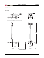
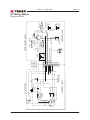
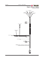
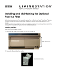
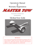
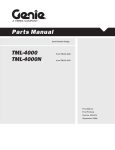
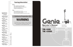
June 2013
Introduction
Important
Read, understand and obey the safety rules and
operating instructions in the appropriate
Operator's Manual on your machine before
attempting any maintenance procedure.
Basic mechanical, hydraulic and electrical
skills are required to perform most procedures.
However, several procedures require specialized
skills, tools, lifting equipment and a suitable
workshop. In these instances, we strongly
recommend that maintenance and repair be
performed at an authorized TEREX dealer
service center.
Technical Publications
TEREX Corporation has endeavored to deliver the
highest degree of accuracy possible. However,
continuous improvement of our products is a
TEREX policy. Therefore, product specifications
are subject to change without notice.
Readers are encouraged to notify TEREX of errors
and send in suggestions for improvement. All
communications will be carefully considered for
future printings of this and all other manuals.
Contact Us:
Copyright © 2009 by TEREX Corporation
[email protected]
116694 June 2013
First Edition, Second Printing
TEREX and "Super Quiet" are registered
trademarks of TEREX USA LLC in the USA and
many other countries.
Printed on recycled paper
Printed in U.S.A.
ii
RL4000 • TML-4000
Part No. 116694
June 2013
Revision History
Revision
Date
Section
Procedure / Schematic Page / Description
B
6/2013
6 - Schem.
Updates and additions.
REFERENCE EXAMPLES:
Kubota Engine_Section 2_Specifications.
A-6,B-3,C-7_Section 3_Maintenance Procedure.
3-2, 6-4, 9-1_Section 4_Repair Procedure.
Fault Codes_Section 5.
6-35, 6-56, 6-104_Section 6_Schematic Page #.
Part No. 116694
Electronic Version
Click on any procedure or page number
highlighted in blue to view the update.
RL4000 • TML-4000
iii
June 2013
REVISION HISTORY, CONTINUED
Revision
Date
Section
Procedure / Schematic Page / Description
REFERENCE EXAMPLES:
Kubota Engine_Section 2_Specifications.
A-6,B-3,C-7_Section 3_Maintenance Procedure.
3-2, 6-4, 9-1_Section 4_Repair Procedure.
Fault Codes_Section 5.
6-35, 6-56, 6-104_Section 6_Schematic Page #.
iv
Electronic Version
Click on any procedure or page number
highlighted in blue to view the update.
RL4000 • TML-4000
Part No. 116694
June 2013
How to Read Your Serial Number
Serial Number Legend
The serial number plate on your
RL4000/TML-4000 is located on the cabinet next
to the light tower mast.
RL4
08 - 1003
Model
Sequence
number
Model year
Part No. 116694
RL4000 • TML-4000
v
Section 1 • Safety Rules
June 2013
Safety Rules
Personal Safety
Any person working on or around a machine must
be aware of all known safety hazards. Personal
safety and the continued safe operation of the
machine should be your top priority.
Danger
Failure to obey the instructions and safety rules
in this manual and the appropriate Operator's
Manual on your machine will result in death or
serious injury.
Many of the hazards identified in the
operator’s manual are also safety hazards
when maintenance and repair procedures
are performed.
Do Not Perform Maintenance
Unless:
You are trained and qualified to perform
maintenance on this machine.
You read, understand and obey:
- manufacturer’s instructions and safety rules
- employer’s safety rules and worksite
regulations
- applicable governmental regulations
You have the appropriate tools, lifting
equipment and a suitable workshop.
Read each procedure thoroughly. This
manual and the decals on the machine,
use signal words to identify the following:
Safety alert symbol—used to alert
personnel to potential personal
injury hazards. Obey all safety
messages that follow this symbol
to avoid possible injury or death.
Red—used to indicate the
presence of an imminently
hazardous situation which, if not
avoided, will result in death or
serious injury.
Orange—used to indicate the
presence of a potentially
hazardous situation which, if not
avoided, could result in death or
serious injury.
Yellow with safety alert symbol—
used to indicate the presence of a
potentially hazardous situation
which, if not avoided, may cause
minor or moderate injury.
Yellow without safety alert
symbol—used to indicate the
presence of a potentially
hazardous situation which, if not
avoided, may result in property
damage.
vi
RL4000 • TML-4000
Part No. 116694
June 2013
Section 1 • Safety Rules
SAFETY RULES
Be sure to wear protective eye wear and
other protective clothing if the situation
warrants it.
Be aware of potential crushing hazards
such as moving parts, free swinging or
unsecured components when lifting or
placing loads. Always wear approved steel-toed
shoes.
Workplace Safety
Be sure to keep sparks, flames and
lighted tobacco away from flammable and
combustible materials like battery gases
and engine fuels. Always have an approved fire
extinguisher within easy reach.
Be sure that all tools and working areas
are properly maintained and ready for
use. Keep work surfaces clean and free
of debris that could get into machine components
and cause damage.
Be sure that your workshop or work area
is properly ventilated and well lit.
Be sure any forklift, overhead crane or
other lifting or supporting device is fully
capable of supporting and stabilizing the
weight to be lifted. Use only chains or straps that
are in good condition and of ample capacity.
Be sure that fasteners intended for one
time use (i.e., cotter pins and self-locking
nuts) are not reused. These components
may fail if they are used a second time.
Be sure to properly dispose of old oil or
other fluids. Use an approved container.
Please be environmentally safe .
Part No. 116694
RL4000 • TML-4000
vii
June 2013
Table of Contents
Introduction
Important Information - Introduction .................................................................. ii
Revision History ................................................................................................ iii
How to Read Your Serial Number .................................................................... v
Section 1
Safety Rules
General Safety Rules ....................................................................................... vi
Section 2
Specifications
Model - RL4000 and TML-4000 ................................................................... 2 - 1
RL4000 ........................................................................................................ 2 - 2
TML-4000 .................................................................................................... 2 - 3
SAE and Metric Fastener Torque Charts ..................................................... 2 - 4
Section 3
Scheduled Maintenance Procedures
Introduction .................................................................................................. 3 - 1
Pre-delivery Preparation Report .................................................................. 3 - 3
Maintenance Schedules
Kubota Lubrication and Maintenance Service Intervals ............................... 3 - 5
Perkins Lubrication and Maintenance Service Intervals .............................. 3 - 6
Marathon Generators Maintenance Schedule ............................................. 3 - 7
Section 4
Troubleshooting
Introduction .................................................................................................. 4 - 1
Troubleshooting Guide ................................................................................ 4 - 2
viii
RL4000 • TML-4000
Part No. 116694
June 2013
TABLE OF CONTENTS
Section 5
Schematics
Introduction .................................................................................................. 5 - 1
DC Wiring, Kubota ....................................................................................... 5 - 2
Engine Harness, Kubota .............................................................................. 5 - 3
DC Wiring, Perkins ...................................................................................... 5 - 4
Engine Harness, Perkins ............................................................................. 5 - 5
Wire Harness, Inside Control Box, DC ........................................................ 5 - 6
MH Light Fixture .......................................................................................... 5 - 7
1000 MH Ballast .......................................................................................... 5 - 8
Part No. 116694
RL4000 • TML-4000
ix
June 2013
This page intentionally left blank.
x
RL4000 • TML-4000
Part No. 116694
Section 2 • Specifications
June 2013
Specifications
Model - RL4000 & TML-4000
Height, stowed
5 ft 9.5 in
1.765 m
Length, stowed
14 ft 2 in
4.331 m
Width, stowed
4 ft 6 in
1.372 m
30 ft
9.114 m
Extended tower height
Weight
1725 lbs
783 kg
(Machine weights vary with option configurations. See
serial label for specific machine weight.)
Maximum tongue weight
199 lbs
Tire size, U.S.
P175/80D13 Load B
Engine type
Fuel capacity
Run time
Generator
Kubota 13.6 HP
Perkins 13.8 HP
30 gallons
Tower rotation
114 liters
Kubota 38.3 hours
Perkins 37.9 hours
Marathon 6 kW, 60 Hz
Total lighting wattage
Four lights
Replacement bulbs
91 kg
4000 watts
1000 watts
Type BT-37 Metal Halide
359 degrees,
non-continuous
Maximum towing speed
60 mph
97 km/h
Maximum wind speed rating
62 mph
100 km/h
71 dba @
23 ft / 7 m
Sound level (dba rating)
Part No. 116694
RL4000 • TML-4000
2-1
Section 2 • Specifications
June 2013
SPECIFICATIONS
RL4000
69 1/2"
(1765mm)
170 1/2"
(4331mm)
TRAVEL POSITION
360"
(9144mm)
38"
(965mm)
61 1/2"
(1562mm)
54"
(1372mm)
124"
(3150mm)
126"
(3200mm)
OPERATING POSITION
2-2
RL4000 • TML-4000
Part No. 116694
Section 2 • Specifications
June 2013
SPECIFICATIONS
TML-4000
69 1/2"
(1765mm)
170 1/2"
(4331mm)
TRAVEL POSITION
360"
(9144mm)
38"
(965mm)
61 1/2"
(1562mm)
54"
(1372mm)
124"
(3150mm)
126"
(3200mm)
OPERATING POSITION
Part No. 116694
RL4000 • TML-4000
2-3
Section 2 • Specifications
June 2013
SPECIFICATIONS
4.6
2-4
8.8
RL4000 • TML-4000
10.9
12.9
Part No. 116694
Section 3 • Scheduled Maintenance Procedures
June 2013
Scheduled Maintenance Procedures
About This Section
This section contains detailed procedures for each
scheduled maintenance inspection.
Each procedure includes a description, safety
warnings and step-by-step instructions.
Observe and Obey:
Symbols Legend
Safety alert symbol—used to alert
personnel to potential personal
injury hazards. Obey all safety
messages that follow this symbol
to avoid possible injury or death.
Maintenance inspections shall be completed by
a person trained and qualified on the
maintenance of this machine.
Scheduled maintenance inspections shall be
completed as specified using the supplied
Lubrication and Maintenance Service Interval
Charts provided in this section.
Red—used to indicate the
presence of an imminently
hazardous situation which, if not
avoided, will result in death or
serious injury.
Failure to perform each procedure
as presented and scheduled could
result in death, serious injury or
substantial damage.
Orange—used to indicate the
presence of a potentially
hazardous situation which, if not
avoided, could result in death or
serious injury.
Immediately tag and remove from service a
damaged or malfunctioning machine.
Repair any machine damage or malfunction
before operating the machine.
Yellow with safety alert symbol—
used to indicate the presence of a
potentially hazardous situation
which, if not avoided, may cause
minor or moderate injury.
Keep records on all inspections for three years.
Machines that have been out of service for a
period longer than 3 months must complete the
quarterly inspection.
Yellow without safety alert
symbol—used to indicate the
presence of a potentially
hazardous situation which, if not
avoided, may result in property
damage.
Unless otherwise specified, perform each
maintenance procedure with the machine in
the following configuration:
• Machine parked on a firm, level surface
• Toggle switch in the off position
• Wheels chocked
Indicates that a specific result is expected after
performing a series of steps.
Indicates that an incorrect result has occurred
after performing a series of steps.
Part No. 116694
RL4000 • TML-4000
3-1
Section 3 • Scheduled Maintenance Procedures
June 2013
This page intentionally left blank.
3-2
RL4000 • TML-4000
Part No. 116694
Pre-Deliver
Pre-Deliveryy Preparation
Fundamentals
Instructions
It is the responsibility of the dealer to perform the
Pre-delivery Preparation.
Use the operator’s manual on your machine.
The Pre-delivery Preparation is performed prior to each
delivery. The inspection is designed to discover if anything
is apparently wrong with a machine before it is put into
service.
A damaged or modified machine must never be used. If
damage or any variation from factory delivered condition
is discovered, the machine must be tagged and removed
from service.
Repairs to the machine may only be made by a qualified
service technician, according to the manufacturer's
specifications.
Scheduled maintenance inspections shall be performed
by qualified service technicians, according to the
manufacturer's specifications and the requirements listed
in the responsibilities manual.
The Pre-delivery Preparation consists of completing the
Pre-operation Inspection, the Maintenance items and the
Function Tests.
Use this form to record the results. Place a check in the
appropriate box after each part is completed. Follow the
instructions in the operator’s manual.
If any inspection receives an N, remove the machine from
service, repair and re-inspect it. After repair, place a check
in the R box.
Legend
Y = yes, completed
N = no, unable to complete
R = repaired
Comments
Pre-Delivery Preparation
Pre-operation inspection completed
Maintenance items completed
Function tests completed
Model
Serial number
Date
Machine owner
Inspected by (print)
Inspector signature
Inspector title
Inspector company
TEREX USA, LLC
Nyala Farm Road
Westport, CT 06880 USA
Toll Free (800) 433-3026 in U.S.A. and Canada
Copyright © 2006 by TEREX Corporation. TEREX® is a registered trademark of TEREX USA,
LLC.
Rev C
Y
N
R
Section 3 • Scheduled Maintenance Procedures
June 2013
This page intentionally left blank.
3-4
RL4000 • TML-4000
Part No. 116694
Section 3 • Scheduled Maintenance Procedures
June 2013
Maintenance Schedules
Kubota Lubrication and Maintenance Service Intervals
ITEM
Check of fuel pipes and clamp bands
Check engine oil and coolant level
Cleaning of air cleaner element
Check of battery electrolyte level
Check of fan belt tightness
Every 50
Hours
Every
100
Hours
Every
200
Hours
Every
400
Hours
Every
500
Hours
Every
Year
Every
800
Hours
Every
1500
Hours
Every
3000
Hours
Every
Two
Years
•
•
•
•
•
Check of radiator hoses and clamp
bands
•
•
Check of intake air line
•
•
Replacement of oil filter cartridge
Replacement of fuel filter cartridge
Removal of sediment in fuel tank
•
Cleaning of water jacket (radiator
interior)
•
•
Replacement of fan belt
•
Replacement of air cleaner element
Check of damage in electric wiring
and loose connections
•
•
Check of valve clearance
Check of fuel injection nozzle injection
pressure
•
•
•
•
Check of turbo charger
Check of injection pump
Check of injection timer
Replacement of battery
•
•
Replacement of radiator hoses and
clamp bands
•
Change of radiator coolant (L.L.C.)
Replacement of fuel pipes and clamp
bands
•
•
Replacement of intake air line
*Refer to the manufacturer's manuals for detailed maintence intervals and instructions. If the
information in the manufacturer's manual differs from that in this manual the manufacturer's manual
should take precedence.
Kubota Engine Manual
Genie part number
Part No. 116694
893020
RL4000 • TML-4000
3-5
Section 3 • Scheduled Maintenance Procedures
June 2013
MAINTENANCE SCHEDULES CONTINUED
Perkins Lubrication and Maintenance Service Intervals
ITEM
Daily
Cooling system coolant level - check
Driven equipment - check
•
•
Engine air cleaner service indicator inspect
•
Engine air precleaner - check/clean
Engine oil level - check
•
Walk around inspection
•
Alternator and fan belts inspect/adjust
Fuel system filter - replace
Battery electrolyte level - check
Every
250
Hours
Every
500
Hours
Every
3000
Hours
Every
6000
Hours
Every
12000
Hours
•
•
•
•
Engine air cleaner element (dual
element) - clean/replace
•
Engine air cleaner element (single
element) - inspect/replace
•
Radiator - clean
Every
2000
Hours
•
Cooling system supplemental coolant
additive (SCA) - test/add
Engine oil and filter - change
Hoses and clamps- inspect/replace
Every
1000
Hours
•
•
Fuel system primary filter/water
separator - drain
Fuel tank water and sediment - drain
Every 50
Hours
•
•
•
•
•
•
Alternator and fan belts - replace
Engine valve lash - inspect/adjust
Turbocharger - inspect
•
•
•
•
Alternator - inspect
Engine crankcase breather - replace
Engine mounts - inspect
Starter motor - inspect
•
•
Fuel injector - test/change
Water pump - inspect
Cooling system coolant (commercial
heavy-duty) - change
Cooling system coolant extender
(ELC) - add
Cooling system coolant (ELC) change
•
•
•
Perkins Operations Manual
3-6
RL4000 • TML-4000
Part No. 116694
Section 3 • Scheduled Maintenance Procedures
June 2013
MAINTENANCE SCHEDULES CONTINUED
Marathon Generators Maintenance Schedule
ITEM
DAILY
200 Hours
10000
Hours
•
Visual inspection
Clean and inspect after every 200 hours of
normal operating time. If generator is housed
in a harsh environment, it is advisable to clean
and inpect the unit more frequently.
•
•
Replace the bearing
*Refer to the manufacturer's manuals for detailed maintence intervals and instructions. If the
information in the manufacturer's manual differs from that in this manual the manufacturer's manual
should take precedence.
Marathon Manual
Genie part number
Part No. 116694
116188
RL4000 • TML-4000
3-7
Section 3 • Scheduled Maintenance Procedures
June 2013
This page intentionally left blank.
3-8
RL4000 • TML-4000
Part No. 116694
June 2013
Section 4 • Troubleshooting
Troubleshooting
Before Troubleshooting:
Read, understand and obey the safety rules
and operating instructions in the appropriate
operator's manual on your machine.
Be sure that all necessary tools and test
equipment are available and ready for use.
Observe and Obey:
Troubleshooting and repair procedures shall be
completed by a person trained and qualified on
the repair of this machine.
Be aware of the following hazards and follow
generally accepted safe workshop practices.
Immediately tag and remove from service a
damaged or malfunctioning machine.
Repair any machine damage or malfunction
before operating the machine.
Unless otherwise specified, perform each
repair procedure with the machine in the
following configuration:
• Machine parked on a firm, level surface.
• Wheels chocked.
• Toggle switch in off position.
Electrocution/burn hazard.
Exposure to electrically charged
circuits could result in death or
serious injury. Remove all rings,
watches and other jewelry.
Electrocution/burn hazard.
Attempting to sevice the machine
before the capacitors are fully
discharged will result in death or
serious injury.
High voltage. Exposure to
electrical wires or electrical
current will result in death or
serious injury. Remove all rings,
watches and other jewelry. Turn
off all power when not needed for
testing. Use extreme caution
when working with high voltage
electrical components.
Burn hazard. Contact with hot
engine components may cause
severe burns. Use caution when
working around a hot engine.
Part No. 116694
RL4000 • TML-4000
4-1
Section 4 • Troubleshooting
June 2013
Troubleshooting Guide
The engine/generator set is tested and set at the factory for proper operation in the field. These units
should never require additional adjustments in the field. If needed, adjustments should only be made by
a qualified service technician, otherwise the manufacturer’s warranty may become void.
TROUBLE
1.Boom will not rise to
the operating position.
POSSIBLE CAUSE
a.Upper retaining pin is in place
b.Defective cable
or pulley
c.Defective winch
2.Boom will not telescope.
a.Defective winch
b.Broken cable or pulley
3.Engine will not turn over
a.Dead battery
b.Engine has seized due to loss
of fluids
4.Engine turns over but will
not start
a.Empty fuel tank
b.Clogged fuel lines or filter
5.Engine runs rough
c.Leaking fuel lines or a loss
of prime
d.Heater elements burned out
e.Fuel line solenoid is not open
a.Clogged or leaking fuel system
b.Clogged exhaust system
c.Clogged air filter
d.Clogged or stuck fuel injectors
e.Valve clearances are out of
adjustment or the valve spring
may be damaged
f.Defective governor or fuel pump
4-2
RL4000 • TML-4000
REMEDY
a.Remove upper retaining pin
b.Have a trained
mechanic examine and
repair as needed
c.Have a trained
mechanic examine
and replace as needed
a.Have a trained
mechanic examine
and replace as needed
b.Have a trained
mechanic examine
and replace as needed
a.Check the battery voltage or
loose cables
b.Have a trained
mechanic examine and
repair as needed
a.Fill tank with #2 diesel fuel
b.Check and clean the fuel
system as needed
c.Replace any leaking fuel lines
and tighten connections
d.Replace heater elements
e.Replace fuel line solenoid
a.Replace fuel lines, tighten all
connections, inspect the pickup
tube and inspect the fuel filter
b.Clear the exhaust system
c.Clear air filter
d.Have a trained
mechanic examine
e.Have a trained
mechanic examine
f.Have a trained
mechanic examine
Part No. 116694
June 2013
Section 4 • Troubleshooting
TROUBLESHOOTING
TROUBLE
POSSIBLE CAUSE
6.Engine runs but produces a
dense smoke
a.Crankcase oil level is too high
b.Low compression
7.Engine overheats
c. Clogged air cleaner
a.Blocked cooling air intakes
b.Low coolant levels
8.Engine runs but the battery
voltage is low
9.Engine runs but the lights will
not operate
c.Radiator fins have become
clogged
d.Fan belt is loose
a.Alternator has failed
a.Circuit breakers are tripped
b.Loose connections in the wiring
system
c.Burned out bulb
d.Defective capacitor
(Leroy Somers Generator)
e.Defective AC generator
f.Engine speed is too low
g.Defective ballast and capacitors
10.Unusual noise coming from
the generator
11.Lamp will not start
a.The generator has a defective
bearing or damaged fan blade
a.Lamp loose in socket
b.Floodlight plugs not tight
c.Defective ballast
d.Low voltage
Part No. 116694
RL4000 • TML-4000
REMEDY
a.Drain oil to its proper level
b.Have a trained mechanic
inspect for broken or seized
rings. Inspect valve clearances
c. Replace air cleaner element
a.Inspect the front and rear intakes
and clear as needed
b.Replace the coolant with a 50%
water/coolant solution
c.Clear the radiator fins
d.Tighten fan belt
a.Have a trained mechanic inspect
the alternator
a.Reset the circuit breaker
b.Have a trained electrician inspect
the ballast box wiring system
c.Replace the bulbs as needed
d.Have a trained electrician inspect
the capacitor
e.Have a trained electrician inspect
the generator
f.Have a trained mechanic inspect
the engine speed and reset to
1800rpm @ 60hz
g.Have a trained electrician inspect
the ballast and capacitors
a.Have a trained electrician inspect
the generator
a.Inspect lamp base to see if there
is arcing at center contact button.
Tighten lamp. Check socket for
damage. Replace if needed.
b.Check plug and receptacle. Tighten
if needed. Make sure power is off.
c.Interchange ballast plugs. If lamp
starts, replace ballast. Check for
swollen capacitors, charred wiring,
core and coil, or other signs of
excessive heat.
d.Check line voltage at ballast input.
Voltage should be within 10% of
rating when operating at normal load.
Increase supply voltage or remove
external load.
4-3
Section 4 • Troubleshooting
June 2013
TROUBLESHOOTING
TROUBLE
11.Lamp will not start
12.Lamp starts slowly (arc does
not strike when switch is first
turned on
13.Circuit breaker trips on lamp
startup
14.Lamp light output low
POSSIBLE CAUSE
e.Improper ballast
f.Lamp has been operating; cool
down time insufficient
a.Defective lamp
a.Short circuit or ground
a.Normal lamp depreciation
b.Dirty lamp or fixture
c.Defective ballast
d.Wrong voltage
e.Improper ballast
15.Lamp colors different
a.Normal lamp depreciation
b.Dirty lamp or fixture
c.Wrong lamp
16.Arc tube discolored or swollen
a.Over voltage from power supply
b.Improper ballast
17.Short lamp life
a.Lamp damaged
b.Improper ballast
18.Lamp flickers or goes outintermittent or cycling
a.Improper Ballast
b.New lamp
4-4
RL4000 • TML-4000
REMEDY
e.The ballast name plate data should
agree with the line voltage and lamp
used. If not, replace the ballast.
f.Switch off breaker and allow lamp
to cool.
a.Lamp may glow for an extended
period of time. Replace after
checking voltage and ballast
a.Check wiring against diagram.
inspect for shorts or ground. Fix as
needed.
a.Replace lamp
b.Clean lamp and fixture
c.Interchange ballast plugs. If lamp
starts, replace ballast. Check for
swollen capacitors, charred wiring,
core and coil, or other signs of
excessive heat.
d.Check line voltage at ballast input.
Voltage should be within 10% of
rating when operating at normal load.
Check wiring connections for voltage
loss. Check socket contact point.
e.Check ballast name plate against
lamp data
a.Replace lamp
b.Clean lamp and fixture
c.Check data on lamps and replace
as needed.
a.Check voltage at ballast, for current
or voltage surges, for shorted
capacitors and replace as needed
b.Check ballast name plate against
lamp data
a.Check for outer bulb cracks,
cracks where lamp meets base, and
for broken arc tube or loose metal
parts. Replace as needed.
b.Check ballast name plate against
lamp data
a.Check ballast name plate against
lamp data
b.Under certain conditions new lamps
may "cycle". Usually after 3 tries to
start at 30 to 60 second intervals,
lamp will stabilize and operate normal
Part No. 116694
June 2013
Section 4 • Troubleshooting
TROUBLESHOOTING
TROUBLE
18.Lamp flickers or goes outintermittent or cycling
POSSIBLE CAUSE
c.Defective lamp
d.High spike ballast
REMEDY
c.Replace lamp
d.Ballast produces high spike current.
Measure with oscilloscope. Replace
ballast as required.
IF YOU FEEL AN ELECTRIC SHOCK AT ANY TIME WHILE OPERATING THIS UNIT, SHUT IT
DOWN IMMEDIATELY! HAVE THE UNIT INSPECTED BY A TRAINED ELECTRICIAN.
THIS ENGINE/GENERATOR SET IS FACTORY INSTALLED, TESTED, AND SET FOR FIELD
OPERATION. ANY DAMAGE TO THE ENGINE OR GENERATOR UNITS OCCURRING AFTER
ADJUSTMENTS ARE MADE IN THE FIELD BY UNAUTHORIZED PERSONNEL WILL NOT BE
COVERED BY YOUR MANUFACTURER’S WARRANTY AND WILL ALSO VOID THE
MANUFACTURER’S WARRANTY ON THIS PARTICULAR UNIT. IF YOU CAN NOT REACH YOUR
LOCAL DEALER, CONTACT THE FACTORY SERVICE MANAGER TOLL FREE AT 1-800-433-3026.
Light Fixture Troubleshooting
DO NOT OPEN FIXTURE WHILE LIGHT
CIRCUIT BREAKER IS “ON”. ALLOW
LAMP TO COOL BEFORE TOUCHING.
**TAKE EXTRA PRECAUTIONS WHEN
TROUBLESHOOTING ELECTRICAL PROBLEMS**
A. Only use a voltmeter with two well-insulated pin probes rated for 600 volts.
B. Treat all conductors as potentially hot.
C. Proceed through circuits systematically,
operating only one section at a time.
D. Before disconnecting ballast, turn off circuit
breaker and wait 30 seconds for capacitor
to discharge.
E. If all the lights are out and all the ballasts
are receiving power, suspect burned out
power cable.
Part No. 116694
RL4000 • TML-4000
4-5
Section 4 • Troubleshooting
June 2013
This page intentionally left blank.
4-6
RL4000 • TML-4000
Part No. 116694
June 2013
Section 5 • Schematics
Schematics
About This Section
There are two groups of schematics in this section.
An illustration legend precedes each group of
drawings.
Electrical Schematics
Observe and Obey:
Electrocution/burn hazard. Contact
with electrically charged circuits
could result in death or serious
injury. Remove all rings, watches
and other jewelry.
Troubleshooting and repair procedures shall be
completed by a person trained and qualified on
the repair of this machine.
Immediately tag and remove from service a
damaged or malfunctioning machine.
Repair any machine damage or malfunction
before operating the machine.
Before Troubleshooting:
General Repair Process
Malfunction
discovered
Read, understand and obey the safety rules
and operating instructions in the appropriate
operator's manual on your machine.
Be sure that all necessary tools and test
equipment are available and ready for use.
Part No. 116694
Identify
symptoms
Troubleshoot
problem
still exists
Return to
service
RL4000 • TML-4000
problem
solved
Inspect
and test
Perform
repair
5-1
5-2
GRN
YEL
RL4000 • TML-4000
BAT
IGN
HOUR
METER
BLK
1
2
3
4
5
6
7
8
9
10
11
12
P1
11
1 RED
2 ORG
3 GRN
4 WHT
5 BLK
6 YEL
7 BRN
8
9
10
11
12
1
4
7
10
N.C.
E-STOP
(OPTION)
RED
GLOW
PLUGS
ST
STARTER
B+
WH/RD
FUEL
PUMP
WHT
OIL PRESS.
SWITCH (NC)
TEMPERATURE
SWITCH (NO)
ORG
FUEL
SOLENOID
PULL
BRN
HOLD
HARNESS 116820
WH/BK
BRN
ALTERNATOR
GRN
L
B IG VIO
FUSE
30A
RED
+
BATTERY
12V DC
BLK
OR/BK
HARNESS 116815
BRN
YEL
RED
ORG
GRN
WHT
BLK
YEL
BRN
3
6
9
12
P1
2
RED BLK
RED
WHT
WHT
YEL
BRN
YEL
RED
ENGINE COMPONENTS
WH/BK
ACC
ST
86
ORG 85
RELAY 12V
SPST (NC)
87a
87
PREHEAT
PUSH BUTTON
YEL
GRN
CONTROL BOX
BRN 30
ALTERNATOR
FAILURE
LIGHT
Section 5 • Schematics
June 2013
DC Wiring, Kubota
Drawing #116814C
Part No. 116694
June 2013
Section 5 • Schematics
Engine Harness, Kubota
Drawing #116820B
STARTER ALTERNATOR
(IG)
BATT +
ALTERNATOR
(B+)
STARTER
SOLENOID
OIL PRESSURE
SWITCH
STARTER
SOLENOID
FUEL SOLENOID
TEMPERATURE
SWITCH
GLOW PLUGS
GROUND
FUEL PUMP
FUSE
30A
E-STOP
(OPTION)
P1
Part No. 116694
RL4000 • TML-4000
5-3
5-4
GRN
RL4000 • TML-4000
IGN
86
ORG 85
YEL
WHT
WHT
RED
HOUR
METER
BRN
YEL
RED
ORG
GRN
WHT
BLK
YEL
BRN
YEL
3
6
9
12
1
2
3
4
5
6
7
8
9
10
11
12
P1
11
P1
2
1
2
3
4
5
6
7
8
9
10
11
12
RED
VIO
GRN
WHT
BLK
YEL
RED
YEL
1
4
7
10
N.C.
RED
2
BLU
4
5
6
VOLTAGE REGULATOR
BLK
BLU
1
STARTER
ST
WHT
YEL
3
B+
B IG BLU
ALTERNATOR
FUSE
30A
GRN
BRN
HARNESS 116822
GLOW
PLUGS
E-STOP
(OPTION)
+
BATTERY
12V DC
RED
VIO
RED
5
2
6
3
BLU BLK BLU
GRN YEL RED
4
1
PRESSURE
SWITCH (NC)
TEMPERATURE
SWITCH (NO)
FUEL
SOLENOID
POWER
GND
(VIEW FROM WIRE ENTRY SIDE)
ENGINE COMPONENTS
RED
HARNESS 116815
ST
BAT
ACC
YEL
RELAY 12V
SPST (NC)
87a
87
YEL
PREHEAT
PUSH BUTTON
BRN 30
ALTERNATOR
FAILURE
LIGHT
GRN
BLK
ORG
CONTROL BOX
Section 5 • Schematics
June 2013
DC Wiring, Perkins
Drawing #116819B
BLK
Part No. 116694
June 2013
Section 5 • Schematics
Engine Harness, Perkins
Drawing #116822B
BLU
1
BLK
2
BLU
3
4
GRN
5
YEL
6
RED
VOLTAGE REGULATOR
GROUND
STARTER
BATT +
ALTERNATOR
TEMPERSTURE
SWITCH
STARTER
SOLENOID
GLOW PLUGS
GROUND
OIL PRESSURE SWITCH
FUEL SOLENOID
FUSE
30A
PERKINS ENGINE
CONNECTOR REFERENCE
BLU
1
BLK
2
BLU
3
4
5
6
YEL
RED
GRN
(WIRE ENTRY VIEW)
E-STOP
(OPTION)
2
2
1
1
FUEL SOLENOID BLK RED
OIL PRESS SWITCH VIO BLK
WATER TEMP SWITCH ORN BLK
Part No. 116694
RL4000 • TML-4000
P1
5-5
5-6
RL4000 • TML-4000
PUSHBUTTON
OUT
WHITE 12 AWG
YELLOW 14 AWG
BROWN 14 AWG
20A GFCI
(GROUND)
KEYSWITCH
ACCESSORY
KEYSWITCH
STARTER
PUSH BUTTON
IN
HOUR METER
(NEGATIVE)
30A TWISTLOCK
(GROUND)
KEYSWITCH
STARTER
RED 14 AWG
INDICATOR IN
BROWN 14 AWG
TIES TO BALLAST
CORD NEUTRALS
WITH WHITE FROM
10/4 CABLE
TERMINATION INFO
PUSHBUTTON
IN
YELLOW 14 AWG
WHITE 14 AWG
BROWN 14 AWG
BLACK 14 AWG
INDICATOR
OUT
BROWN 14 AWG
GREEN 14 AWG
ORANGE 14 AWG
GREEN 14 AWG
ORANGE 14 AWG
KEYSWITCH
IGNITION
RED 12 AWG
KEYSWITCH
BATTERY
ISUZU & PERKINS
THE GREEN WIRE
MUST BE REMOVED
FROM THE IGNITION KEYSWITCH
IGNITION
SWITCH AND
ATTACHED TO
GROUND
20A GFCI
RECEPTACLE
(NEUTRAL)
BLACK 14 AWG
GREEN 10 AWG
GREEN 12 AWG
BROWN 14 AWG
KEYSWITCH
STARTER
CHASSIS
GROUND
(STUD)
HOUR METER(+)
WHITE 14 AWG
Section 5 • Schematics
June 2013
Wire Harness, Inside Control Box, DC
Drawing #116815F
Part No. 116694
Part No. 116694
WHITE (BLUE)
RL4000 • TML-4000
EUROPEAN COLOR
UCODE
LIGHT BLUE
BROWN
GRN/YEL
DOMESTIC COLOR
UCODE
WHITE
BLACK
GREEN
NOTE:
PIN CONFIGURATION IS THE SAMW
FOR TUNGSTEN HALOGEN FIXTURES
BLACK (BROWN)
GREEN (GRN/YEL)
14/3
COMMON FROM BALLAST
HOT FROM BALLAST (LIVE)
GROUND (EARTH)
UCIRCUIT
June 2013
Section 5 • Schematics
MH Light Fixture
Drawing #2985A
5-7
5-8
GRN
RL4000 • TML-4000
CIRCUIT
INPUT 120V
INPUT COMMON
LAMP HOT
LAMP COMMON
GROUND
COLOR
BLACK
WHITE
RED
ORANGE
GREEN
5-POLE
RECEPTACLE
RED
WHITE
BLACK
ORANGE
C1
24mF
480V
COM
120V
CAPACITOR
TRANSFORMER
(1000W METAL HALIIDE BALLAST)
Section 5 • Schematics
June 2013
1000 MH Ballast
Drawing #2986
Part No. 116694
June 2013
Section 5 • Schematics
This page intentionally left blank.
Part No. 116694
RL4000 • TML-4000
5-9
California Proposition 65
California Proposition 65
Warning
Battery post terminals and related
accessories contain lead compounds,
chemicals known to the State of
California to cause cancer
and other reproductive harm.
Warning
The exhaust from this product
contains chemicals known to
the State of California to
cause cancer, birth defects
or other reproductive harm.
Towing Checklist
(Use at each stop)
Before Towing
· Towing hitch is properly secured to tow vehicle
· Safety chains (if required) are properly attached
and secure (chains are crossed below hitch)
· All lights are connected and working
· Tires are properly inflated
Before Driving
· Fasten safety restraints
· Properly adjust mirrors
On The Road
· Do not exceed 60 mph / 97 km/h. Obey all local
and national towing speed laws
· Check connections and tire pressure at each stop
· Slow down for hazardous conditions
· Allow extra distance for following and passing other
vehicles
Genie North America
Phone 425.881.1800
Toll Free USA and Canada
800.536.1800
Fax 425.883.3475
Genie Australia Pty Ltd.
Phone +61 7 3375 1660
Fax +61 7 3375 1002
Phone +86 21 53852570
Fax +86 21 53852569
Genie Malaysia
Phone +65 98 480 775
Fax +65 67 533 544
Genie Japan
Phone +81 3 3453 6082
Fax +81 3 3453 6083
Genie Korea
Phone +82 25 587 267
Fax +82 25 583 910
Genie Brasil
Phone +55 11 41 665 755
Fax +55 11 41 665 754
Genie Holland
Phone +31 183 581 102
Fax +31 183 581 566
Genie Scandinavia
Phone +46 31 575100
Fax +46 31 579020
Genie France
Phone +33 (0)2 37 26 09 99
Fax +33 (0)2 37 26 09 98
Genie Iberica
Phone +34 93 579 5042
Fax +34 93 579 5059
Genie Germany
Phone +49 (0)4202 88520
Fax +49 (0)4202 8852-20
Genie U.K.
Phone +44 (0)1476 584333
Fax +44 (0)1476 584334
Genie Mexico City
Phone +52 55 5666 5242
Fax +52 55 5666 3241
Distributed By:
Genie China