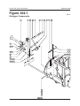
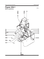
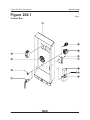
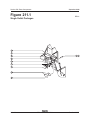
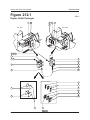
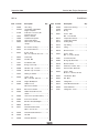
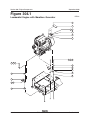
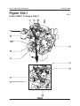
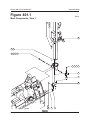
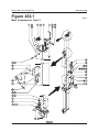
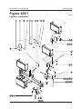
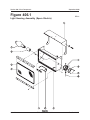
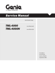
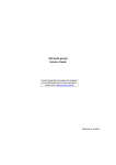
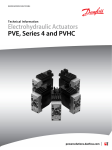
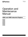
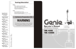
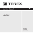
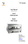
1
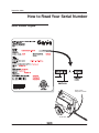
Par ts Manual
Serial Number Range
TML-4000
TML-4000N
from TML01-226
from TML01-226
First Edition
First Printing
Part No. 116471
September 2008
September 2008
Introduction
Important
Serial Number Information
Read, understand and obey the safety rules and
operating instructions in the appropriate Operator's
Manual on your machine before attempting any
maintenance procedure.
Genie Industries offers the following manuals for
these models:
Basic mechanical, hydraulic and electrical
skills are required to perform most procedures.
However, several procedures require specialized
skills, tools, lifting equipment and a suitable
workshop. In these instances, we strongly
recommend that maintenance and repair be
performed at an authorized Genie dealer
service center.
Genie TML-4000N Operator's Manual,
Third Edition .......................................................... 97600
Title
Part No.
Genie TML-4000N Parts Manual,
First Edition ......................................................... 116471
Genie TML-4000N Service Manual,
First Edition ......................................................... 116472
Technical Publications
Genie Industries has endeavored to deliver the
highest degree of accuracy possible. However,
continuous improvement of our products is a Genie
policy. Therefore, product specifications
are subject to change without notice.
Readers are encouraged to notify Genie of errors
and send in suggestions for improvement. All
communications will be carefully considered for
future printings of this and all other manuals.
Contact Us:
Copyright © 2008 by Genie Industries
www.genieindustries.com
e-mail: [email protected]
116471 Rev A September 2008
First Edition, First Printing
"Genie" is a registered trademark of Genie
Industries in the USA and many other countries.
"TML" is a trademark of Genie Industries.
Printed on recycled paper
Printed in U.S.A.
ii
TML-4000 • TML-4000N
Part No. 116471
September 2008
How to Read Your Serial Number
Serial Number Legend
Serial number
stamped on chassis
Serial label
Part No. 116471
TML-4000 • TML-4000N
iii
September 2008
This page intentionally left blank.
iv
TML-4000 • TML-4000N
Part No. 116471
September 2008
Section 1 • Safety Rules
Safety Rules
Danger
Failure to obey the instructions and safety rules
in this manual and the appropriate Operator's
Manual on your machine will result in death or
serious injury.
Many of the hazards identified in the
operator’s manual are also safety hazards
when maintenance and repair procedures
are performed.
Do Not Perform Maintenance
Unless:
You are trained and qualified to perform
maintenance on this machine.
You read, understand and obey:
- manufacturer’s instructions and safety rules
- employer’s safety rules and worksite
regulations
- applicable governmental regulations
You have the appropriate tools, lifting
equipment and a suitable workshop.
Part No. 116471
TML-4000 • TML-4000N
v
Section 1 • Safety Rules
September 2008
SAFETY RULES
Personal Safety
Workplace Safety
Any person working on or around a machine must
be aware of all known safety hazards. Personal
safety and the continued safe operation of the
machine should be your top priority.
Be sure to keep sparks, flames and
lighted tobacco away from flammable and
combustible materials like battery gases
and engine fuels. Always have an approved fire
extinguisher within easy reach.
Read each procedure thoroughly. This
manual and the decals on the machine,
use signal words to identify the following:
Safety alert symbol—used to alert
personnel to potential personal
injury hazards. Obey all safety
messages that follow this symbol
to avoid possible injury or death.
Indicates an imminently hazardous
situation which, if not avoided, will
result in death or serious injury.
Indicates a potentially hazardous
situation which, if not avoided,
could result in death or serious
injury.
Indicates a potentially hazardous
situation which, if not avoided,
may cause minor or moderate
injury.
Indicates a potentially hazardous
situation which, if not avoided,
may result in property damage.
Be sure that all tools and working areas
are properly maintained and ready for
use. Keep work surfaces clean and free of
debris that could get into machine components and
cause damage.
Be sure any forklift, overhead crane or
other lifting or supporting device is fully
capable of supporting and stabilizing the
weight to be lifted. Use only chains or straps that
are in good condition and of ample capacity.
Be sure that fasteners intended for one
time use (i.e., cotter pins and self-locking
nuts) are not reused. These components
may fail if they are used a second time.
Be sure to properly dispose of old oil or
other fluids. Use an approved container.
Please be environmentally safe.
Be sure that your workshop or work area
is properly ventilated and well lit.
Be sure to wear protective eye wear and
other protective clothing if the situation
warrants it.
Be aware of potential crushing hazards
such as moving parts, free swinging or
unsecured components when lifting or
placing loads. Always wear approved steel-toed
shoes.
vi
TML-4000 • TML-4000N
Part No. 116471
September 2008
Table of Contents
Introduction
Important Information ......................................................................................... ii
How to Read Your Serial Number ..................................................................... iii
Parts Stocking List ............................................................................................ x
How to Order Parts .......................................................................................... xii
Service Parts Fax Order Form ........................................................................ xiii
Section 1
Safety Rules
General Safety Rules ........................................................................................ v
Section 7
Rev
B
Section 8
Part No. 116471
Rev
Decals
Figure 101.1
Decals ............................................................................. 100 - 2
Base Components
A
Figure 201.1
Axle and Tongue Components ....................................... 200 - 2
A
Figure 202.1
Outrigger Components .................................................... 200 - 4
A
Figure 203.1
Control Box and Electrical Components .......................... 200 - 6
A
Figure 204.1
Winch installation ............................................................. 200 - 8
A
Figure 205.1
Fuel Tank, Battery and Engine Tray Components ......... 200 - 10
A
Figure 206.1
Control Box .................................................................... 200 - 12
A
Figure 207.1
Covers ........................................................................... 200 - 14
A
Figure 208.1
Winch Components ....................................................... 200 - 16
A
Figure 209.1
Power Cables, Lombardini Models ................................ 200 - 18
A
Figure 210.1
Power Cables, Perkins Models ...................................... 200 - 20
A
Figure 211.1
Single Outlet Packages ................................................. 200 - 22
A
Figure 212.1
Duplex Outlet Packages ................................................ 200 - 24
TML-4000 • TML-4000N
vii
September 2008
TABLE OF CONTENTS
Section 9
Section 10
viii
Rev
Engine Components
A
Figure 301.1
Lombardini Engine, View 1 .............................................. 300 - 2
A
Figure 302.1
Lombardini Engine, View 2 .............................................. 300 - 4
A
Figure 303.1
Lombardini Engine, View 3 .............................................. 300 - 6
A
Figure 304.1
Lombardini Engine with Marathon Generator .................. 300 - 8
A
Figure 305.1
Perkins 403D-11G Engine, View 1 ................................ 300 - 10
A
Figure 306.1
Perkins 403D-11G Engine, View 2 ................................ 300 - 12
Rev
Mast Components
A
Figure 401.1
Mast Components, View 1 ............................................... 400 - 2
A
Figure 402.1
Mast Components, View 2 ............................................... 400 - 4
A
Figure 403.1
Mast Components, View 3 ............................................... 400 - 6
A
Figure 404.1
Mast Components, View 4 ............................................... 400 - 8
A
Figure 405.1
Lightbar Installation ....................................................... 400 - 10
A
Figure 406.1
Light Housing Assembly (Spero Electrical) .................... 400 - 12
A
Figure 406.2
Light Housing Assembly (Eagle Lighting) ...................... 400 - 14
A
Figure 407.1
Power Cable Routing ..................................................... 400 - 16
A
Figure 408.1
Mast Extension Cable Routing ...................................... 400 - 18
TML-4000 • TML-4000N
Part No. 116471
September 2008
TABLE OF CONTENTS
This page intentionally left blank.
Part No. 116471
TML-4000 • TML-4000N
ix
September 2008
Parts Stocking List
Required Parts
Manuals
The following parts are required to perform
maintenance procedures as outlined in the
Genie TML-4000 and TML-4000N Parts and
Service Manual.
Genie Industries offers the following support
documents for these models:
Description
Part No.
Perkins 403D-11G Models
Dielectric Grease ................................................. 66399
Oil Filter ................................................................ 94762
Air Filter ................................................................ 97474
Fuel Filter ............................................................. 62421
V-belt .................................................................... 85071
Valve Cover Breather .......................................... 84860
Title
Part No.
Genie TML-4000 and TML-4000N
Operator's Manual, Third Edition
(after serial number TML04-559) ......................... 97600
Manual of Responsibilities ANSI A92.3 ............... 31587
Lombardini Models
Dielectric Grease ................................................. 66399
Oil Filter ................................................................ 80053
Recommended Parts
Description
Part No.
Genie Gray Paint, 12 Ounce (355 ml) Aerosol ...... 1268
Genie Blue Paint, 12 Ounce (355 ml) Aerosol ....... 1484
Genie Blue Paint, 1 Gallon (3.78 liters) ............... 32150
Genie Gray Paint, 1 Gallon (3.78 liters) ............... 32151
x
TML-4000 • TML-4000N
Part No. 116471
September 2008
This page intentionally left blank.
Part No. 116471
TML-4000 • TML-4000N
xi
September 2008
How To Order Parts
Please be prepared with the following information
when ordering replacement parts for your Genie
product:
Machine model number
Machine serial number
Genie part number
Part description and quantity
Purchase order number
"Ship to" address
Desired method of shipment
Name and telephone number of the
authorized Genie Distributor in your area
Use the Service Parts Fax Order Form on the
next page and fax your order to our Parts
Department.
If you don't know the name of your authorized
distributor, or if your area is not currently serviced
by an authorized distributor, please call Genie
Industries.
Machine Information
Model
Serial Number
Date of Purchase
Authorized Genie Distributor
Phone Number
Genie North America
Telephone (425) 556-6551
Toll Free (877) 367-5606 in U.S.A. and Canada
Fax (425) 556-8659
Genie UK
Parts Telephone (44) (0) 1476 584352
Parts Fax (44) (0) 1476 584340
Genie Australia
Parts Telephone (617) 03375 1660
Parts Fax (617) 03375 1002
Genie France
Parts Telephone (33) (0) 237 26 09 99
Parts Fax (33) (0) 237 31 50 10
Genie Germany
Parts Telephone (49) (0) 4202 885223
Parts Fax (49) (0) 4202 885225
Genie Scandinavia
Parts Telephone (46) (31) 3409612
Parts Fax (46) (31) 3409613
Genie Iberica
Parts Telephone (34) (93) 5795042
Genie Brazil
Parts Telephone (55) (114) 1665755
Parts Fax (55) (114) 1665754
Genie Japan
Parts Telephone (81) (33) 4536082
Parts Fax (81) (33) 4536083
Genie China
Parts Telephone (86) (215) 3852570
Parts Fax (86) (215) 3852569
xii
TML-4000 • TML-4000N
Part No. 116471
Service Parts Fax Order Form
Fax to: (425) 556-8659 or Toll Free: 888-274-6192
International: +1-425-556-8659
Please fill out completely
Date
_________________________________
Account Number _______________________________
Your Name _______________________________
Your Fax Number ______________________________
_________________________________
Your Phone Number ____________________________
_________________________________
Ship To
___________________________________
_________________________________
___________________________________
_________________________________
___________________________________
_________________________________
___________________________________
Purchase Order Number ____________________
Ship Via
___________________________________
Model(s) ______________________________________________________ Serial No.(s) _________________
Optional Equipment __________________________________________________________________________
Part Number
Description
Quantity
Price
remove this page and make copies
remove this page and make copies
Bill To
All back-ordered parts will be shipped when available via the same ship method as the original order
unless Noted below:
Ship complete order only - No back orders
Ship all available parts and contact customer on disposition of back-ordered parts
Other (please specify)
FOR GENIE INDUSTRIES USE ONLY
Order Number ______________
Origin Code ________________
Comments _________________________
Date Scheduled ____________
Ship Condition ______________
__________________________________
Order Total ________________
Terms Code ________________
__________________________________
September 2008
This page intentionally left blank.
xvi
TML-4000 • TML-4000N
Part No. 116471
September 2008
Section 100 • Decals
Section 100
Decals
Part No. 116471
TML-4000 • TML-4000N
100 - 1
Section 100 • Decals
September 2008
Figure 101.1
REV A
Decals
100 - 2
TML-4000 • TML-4000N
Part No. 116471
September 2008
Section 100 • Decals
REV A
Item
—
—
—
—
—
—
FIGURE 101.1
Part No.
97306
97307
116028
116029
97308
97309
Description
Qty.
15
72008
Caution - Turn Off Lights .............. 1
Decal Kit - Safety/Instructional,
TML-4000N, Deutz F3M-1008
(includes items 1-15, 18-22,
24-29, 32, 35, 36, 38-46 and 48)
Decal Kit - Safety/Instructional,
TML-4000, Deutz F3M-1008
(Includes items 1-15,18-22,
24-29, 32-36, 38-46 and 48)
Decal Kit - Safety/Instructional,
TML-4000N, Lombardini
LDW-1003/L
(includes items 1-15, 18-22,
24-29, 32, 35, 36, 38-46 and 48)
Decal Kit - Safety/Instructional,
TML-4000, Lombardini
LDW-1003/L
(Includes items 1-15,18-22,
24-29, 32-36, 38-46 and 48)
Decal Kit - Safety/Instructional,
TML-4000N, Perkins 103-10
(includes items 1-13, 15, 18-22
24-29,32-36, 38-46 and 48)
Decal Kit - Safety/Instructional,
TML-4000, Perkins 103-10
(includes items 1-13. 15, 18-22,
24-29, 32-46 and 48)
16
72009
Cosmetic - Genie TML-4000 ........ 2
17
72010
Cosmetic - Genie TML-4000N ..... 2
18
72018
Label - Raise/Lower Winch .......... 1
19
72019
Danger - High Voltage ................. 1
20
CR51A107
Label - Black Arrow ...................... 1
21
72826
Label - Extend/Retract Winch ...... 1
22
72828
Notice - Tire Specifications .......... 2
24
72870
Caution - Component Contact ..... 2
25
72871
Label - Power Outlet, 120V AC .... 1
26
72874
Label - Locked, Unlocked ............ 1
27
72889
Warning - Transport Hazard ........ 1
28
72890
Notice - Mast Retraction ............... 1
29
72891
Label - Blue Arrow ....................... 2
30
80321
Serial Plate and NHTSA Label
(before serial number
TML04-591) .................................. 1
31
82219
Label - Power Outlets Under
Cover (before serial number
TML02-522) .................................. 1
32
82221
Danger - Electrocution Hazard
(located under ballast cover) ........ 1
33
82222
Caution - Light Storage,
Standard Models .......................... 1
34
82223
Label - Light Storage, Standard
Models .......................................... 4
1
28159
Label - Diesel ............................... 1
2
28161
Warning - Crushing Hazard .......... 6
3
28164
Notice - Hazardous Materials ....... 2
4
28171
Label - No Smoking ...................... 1
5
31072
Manual Storage Container ........... 1
6
52475
Label - Transport Tie-down .......... 2
35
82224
Label - HOT .................................. 8
7
62707
Warning - Tow Speed ................... 1
36
82237
8
65408
Notice - Operating Instructions ..... 1
Danger - High Voltage
(located under ballast cover) ....... 1
9
65409
Notice - Mast Rotation
Instructions ................................... 1
37
97767
Notice - Engine Specifications,
38
82303
Label - Mast Release Latch ......... 1
10
65411
Warning - General Safety ............. 1
39
82304
Control Panel ............................... 1
11
65412
Warning - Transport
Instructions ................................... 1
40
82957
Label - Power Outlets Under
Cover ............................................ 1
12
65414
Danger - Electrocution Hazard .... 2
41
97518
Notice - Lamp Disposal ................ 2
13
65421
Warning - Electrocution,
Generator ..................................... 2
14
65423
Notice - Deutz Engine Specs ....... 1
Part No. 116471
This list continues on the next page
TML-4000 • TML-4000N
100 - 3
Section 100 • Decals
September 2008
FIGURE 101.1
100 - 4
REV A
TML-4000 • TML-4000N
Part No. 116471
September 2008
Section 100 • Decals
REV A
FIGURE 101.1
Item Part No.
Description
42
97602
Warning - Explosion Hazard,
Ether ............................................. 2
43
97635
Warning - Bodily
Injury Hazard ................................ 4
44
97637
Label - Wet Locations .................. 1
45
97638
Label - Lamp
Replacement ................................ 1
46
97661
Label - Grounding Rod
Attachment ................................... 1
47
104533
Serial Number Label .................... 1
48
114007
Caution - Latch Release .............. 1
Part No. 116471
Qty.
TML-4000 • TML-4000N
100 - 5
Section 100 • Decals
September 2008
This page intentionally left blank.
100 - 6
TML-4000 • TML-4000N
Part No. 116471
Section 200 • Base Components
September 2008
Section 200
Base
Components
Part No. 116471
TML-4000 • TML-4000N
200 - 1
Section 200 • Base Components
September 2008
Figure 201.1
REV A
Axle and Tongue Components
1
2
3
4
5
36 37 38
7
6
10 9
8
11
35
2
13 12
34
32 33
7
6
31
14
17 16 16 15
29
30
18
26 27 27 28
19
29
7
6
26 27 27 27 27 28
20
21
20
200 - 2
25
24
TML-4000 • TML-4000N
23
22
Part No. 116471
Section 200 • Base Components
September 2008
REV A
Item
FIGURE 201.1
Part No.
Description
Qty.
1
25969
Spring Clip, 1/4 -20
2
80370
Side Marker Grommet
3
46716
Rubber Bumper ......................... 10
4
80368
Side Marker Light
5
39560
Cable Tie Mount Clip ................... 5
6
80417
Suspension Mount Bolt,
7/16 -20 x 2.5 inches ...................... 6
7
80418
Flange Nut, 7/16 -20
8
4266
9
—
Item
Part No.
Description
Qty.
22
—
57572
57551
Axle Mount Plate, TML-4000 ......... 2
Axle Mount Plate, TML-4000N
23
—
57571
57550
Flange Nut, 1/2 -20, TML-4000 ..... 8
Flange Nut, 3/8 -24, TML-4000N
24
57568
—
57546
Axle, 3500 lbs Capacity,
TML-4000 ..................................... 1
Axle, 2000 lbs Capacity,
TML-4000N
25
57567
Screw - HHC,
1/4 -20 x 2 inches, GR 5
—
69211
80340
80334
Suspension Stop, TML-4000 ........ 2
Suspension Stop, TML-4000N
26
12461
Screw - HHC,
1/2 -13 x 5 inches, GR 8
10
6091
Nylock Nut, 1/4 -20
27
13066
Flat Washer, 1/2 inch
11
57710
Fender .......................................... 2
28
6198
Nylock Nut, 1/2 -13
12
6888
Screw - HHC,
1/4 -20 x 1 inch, GR 5
29
46715
Safety Chain ................................. 2
30
57332
13
6638
Flat Washer, 1/4 inch
14
80369
Side Marker Light
—
57625
Hitch Coupler Assembly,
2 inch ball (shown) ....................... 1
Standard Hitch Assembly
(includes items 30, 31 and 34)
15
10006
Screw - HHC,
3/4 -10 x 5 inches, GR 5
30
69937
16
10256
Flat Washer,
17
10258
Nylock Nut, 3/4 -10
—
—
59720
67535
18
—
57570
57549
U-Bolt, Axle Mount, TML-4000 ..... 4
U-Bolt, Axle Mount, TML-4000N
31
57331
Tongue Screw Jack (includes
mounting hardware) ...................... 1
19
57393
Axle Spring Hanger Plate ............. 2
32
6034
Jam Nut, 1/2 -13, GR 2
20
116021
33
80231
Screw Jack Spacer ...................... 1
34
97333
Tongue Assembly with Decals .... 1
—
—
116025
116023
Tire and Wheel Assembly
TML-4000N ................................... 2
Wheel, 13 inches TML-4000N
Tire, ST 175/80D13 TML-4000N
35
57470
Mast Spring .................................. 1
20
116022
36
6019
—
—
116026
116024
Tire and Wheel Assembly
TML-4000N ................................... 2
Wheel, 15 inches TML-4000N
Tire, ST 205/75D15 TML-4000N
21
46717
Acorn Nut, 1/2 -20 ....................... 10
Part No. 116471
13/16
inch
Double Eye Leaf Spring,
2000 lbs Capacity, TML-4000 ...... 2
Double Eye Leaf Spring,
1400 lbs Capacity, TML-4000N
Hitch Coupler Combo
Assembly with Pintle Ring
Pintle Ring
Coupler 2 inch Ball Lever Lock
Screw - HHC,
-16 x 1.25 inches, GR 5
3/8
37
5397
Flat Washer, 5/16 inch
38
4828
Nylock Nut, 3/8 -16
TML-4000 • TML-4000N
200 - 3
Section 200 • Base Components
September 2008
Figure 202.1
REV A
Outrigger Components
1
2
3
4
5
6
7
8
9
10
11
34
32 33
13 12
30 31
15 14
29
19 18 17 16
28
25 26 27
22 23 24
21
20
18
19
200 - 4
TML-4000 • TML-4000N
Part No. 116471
Section 200 • Base Components
September 2008
REV A
Item
FIGURE 202.1
Part No.
Description
Qty.
Item
Part No.
Description
Qty.
1
57331
Outrigger Screw Jack ................... 2
28
80130
Outrigger Screw Jack Knob .......... 2
2
—
69818
69809
Outrigger, Tank Side .................... 1
Outrigger, Engine Side
29
80232
3
69815
Sleeve Spacer,
0.63 x 0.75 x 0.5 inch ................... 2
Outrigger Screw Jack
Handle Kit (includes items
5, 30, 32 and 33) .......................... 2
30
6034
Jam Nut, 1/2 -13, GR 2
31
80231
Outrigger Screw Jack Handle
Spacer .......................................... 2
32
69879
Jam Nut, 1/4 -20 ............................ 2
33
8915
Screw - HHC,
1/4 -20 x 1.25 inches, GR 5
34
—
—
80127
80128
80129
—
—
13066
2161
Pull Pin Kit .................................... 1
Pull Pin
Pull Pin Compression Spring,
0.66 x 1.38 inches
Flat Washer, 1/2 inch
Cotter Pin, 1/16 x 1 inch
4
69814
Torsion Spring, 0.88 x 0.5 inch ..... 2
5
69813
Outrigger Strut Guide Bushing ..... 2
6
69800
Outrigger Handle .......................... 2
7
32499
Retainer Clip, 0.88 inch ................ 2
8
80003
Outrigger Strut .............................. 2
9
80000
Outrigger Strut Guide ................... 2
10
69649
Compression Spring,
0.953 x 4.38 inches ...................... 2
11
69990
Outrigger Pin Bracket ................... 2
12
69667
Lock Pin ........................................ 2
13
22547
Roll Pin, 3/16 x 1.25 inches
14
6091
Nylock Nut, 1/4 -20
15
8914
Screw - HHC,
1/4 -20 x 0.625 inch, GR 5
16
6198
Nylock Nut, 1/2 -13
17
80323
Strut Guide Spacer ....................... 2
18
6095
Flat Washer, 1/2 inch
19
13854
Screw - HHC,
1/2 -13 x 4.5 inches, GR 8 ............. 4
20
33373
Flat Washer,
0.89 x 1.5 x 0.09 inch
21
80203
Outrigger Pivot Bushing ............... 2
22
38028
Low Profile Nylock Nut, 5/8 -11
23
42191
Hardened Flat Washer,
0.64 x 1.16 x 0.09 inch ................. 2
24
51131
Screw - HHC,
5/8 -11 x 2.5 inches, GR 5
25
5224
Screw - HHC,
3/8 -16 x 2 inches, GR 5
26
6097
Flat Washer, 3/8 inch
27
46017
Jam Nut, 3/8 -16
Part No. 116471
TML-4000 • TML-4000N
200 - 5
Section 200 • Base Components
September 2008
Figure 203.1
REV A
Control Box and Electrical Components
200 - 6
TML-4000 • TML-4000N
Part No. 116471
Section 200 • Base Components
September 2008
REV A
Item
FIGURE 203.1
Part No.
Description
Qty.
1
6888
Screw - HHC,
1/4 -20 x 1 inch, GR 5
2
6356
Lock Washer, 1/4 inch
3
6638
Flat Washer, 1/4 inch
4
25969
Spring Clip, 1/4 -20
5
6019
6
4828
Nylock Nut,
7
66717
Fuse Holder .................................. 1
8
6873
Screw - FHSM,
10-32 x 1 inch, GR 2
9
14392
Low Profile Nylock Nut, 10-32
10
36372
Fuse, 50A, Very Fast Acting ......... 1
11
6002
Low Profile Nylock Nut, 5/16 -18
12
Ref.
Control Box
(refer to Figure 8-F.1, 8-F.2 or 8-F.3
)
13
—
69983
87797
Front Cover, TML-4000 ................ 2
Front Cover, TML-4000N
14
6090
Screw - HHC,
1/4 -20 x 0.75 inch, GR 5
15
6091
Nylock Nut, 1/4 -20
16
8914
Screw - HHC,
1/4 -20 x 0.625 inch, GR 5
17
46716
Rubber Bumper ............................ 2
18
10107
Screw - HHC,
5/16 -18 x 0.75 inch, GR 5
19
33277
Flat Washer, M8
20
6271
Steel Rivet, 1/4 x 0.25 inch
21
80544
Rubber Cushioned Clamp,
1.75 x 0.25 inch ............................ 4
22
—
69884
85201
Capacitor, 480V AC, 60 Hz ........... 4
Capacitor, 540V AC, 50 Hz
23
4512
Nylon Spacer,
0.25 x 0.69 x 0.25 inch
Part No. 116471
Item
Part No.
Description
Qty.
24
69719
Capacitor Mount Bracket .............. 4
25
69798
—
80350
Screw - HHC,
3/8 -16 x 1.25 inches, GR 5
Ballast and Capacitor
Assembly, 120/240V AC, 60 Hz
(includes item 22) ......................... 4
Ballast and Capacitor
Assembly, 120/240V AC, 50 Hz
(includes item 22)
26
80694
Ballast Mount Panel ..................... 1
3/8
27
69773
Weather-stripping,
3/8 inch ............................ 10 inches
28
69773
-16
Weather-stripping,
inch ............................. 15 inches
3/8
29
69773
TML-4000 • TML-4000N
Weather-stripping,
3/8 inch ............................ 28 inches
200 - 7
Section 200 • Base Components
September 2008
Figure 204.1
REV A
Winch installation
1
4
2
5
3
6
7
8
21
9
20
10
9 19 19
11
18
16 3
16 3
14 13 12
17 14
16 3
15
200 - 8
TML-4000 • TML-4000N
Part No. 116471
Section 200 • Base Components
September 2008
REV A
FIGURE 204.1
Item
Part No.
Description
Qty.
—
104189
Winch Bracket
1
6019
Screw - HHC,
3/8 -16 x 1.25 inches, GR 5
2
5397
Flat Washer, 5/16 inch
3
4828
Nylock Nut, 3/8 -16
4
6888
Screw - HHC,
1/4 -20 x 1 inch, GR 5
5
6638
Flat Washer, 1/4 inch
6
6091
Nylock Nut, 1/4 -20
7
69736
Crank Handle Guide ..................... 1
8
69981
—
57408
Crank Handle Extension,
TML-4000 ..................................... 1
Crank Handle Extension,
TML-4000N
9
6086
Low Profile Nylock Nut, 1/2 -13
10
16342
Winch Handle
11
69673
Mast Lock Bar ............................... 1
12
69654
Mast Lock Handle ........................ 1
13
69638
Compression Spring,
0.75 x 8 inches ............................. 1
14
6094
15
57316
Mast Cable Pulley ........................ 1
16
8516
Screw - HHC,
3/8 -16 x 1.5 inches, GR 5
17
69680
Clevis Pin, 5/8 x 1.5 inches
18
15657
Winch Reinforcement Plate .......... 1
19
6034
Jam Nut, 1/2 -13, GR 2
20
80107
Mast Pivot Cable Assembly .......... 1
21
14085
Winch
Part No. 116471
Cotter Pin, 1/8 x 1 inch
TML-4000 • TML-4000N
200 - 9
Section 200 • Base Components
September 2008
Figure 205.1
REV A
Fuel Tank, Battery and Engine Tray Components
200 - 10
TML-4000 • TML-4000N
Part No. 116471
Section 200 • Base Components
September 2008
REV A
Item
—
1
FIGURE 205.1
Part No.
85275
57750
Description
Qty.
Cold Start Accessory
(includes heavy duty battery,
battery tray and oil pan heater)
Fuel Tank, 50 gallons,
TML-4000 ..................................... 1
1
80530
Fuel Tank, 30 gallons,
TML-4000N .................................. 1
2
891520
Elbow, Fitting,
1/4 MNPT x 1/4 inch, 90° ................ 1
3
116034
Hose End, Barbed, 3/16 inch ......... 1
4
44909
Hose Clamp, 1/4 inch .................... 6
5
30490
Fuel Hose, 1/4 inch .... 2 @13 inches
6
C90200200
Hose End, Barbed,
1/4 MNPT x 1/4 inch, 90° ................ 1
7
35418
Hose, 3/16 inch ............ 26.25 inches
8
69734
Fuel Shutoff Valve ........................ 1
9
101726
Gas Cap, Green ........................... 1
10
6888
Screw - HHC,
1/4 -20 x 1 inch, GR 5
11
6091
Nylock Nut, 1/4 -20
12
85271
—
85272
Rear Cover with Decal,
TML-4000 ..................................... 1
Rear Cover with Decal,
TML-4000N
13
57587
Plastic Plug ................................... 1
14
6638
Flat Washer, 1/4 inch
15
6356
Lock Washer, 1/4 inch
16
25969
Spring Clip, 1/4 -20
17
104776
18
6175
Screw - HHC,
3/8 -16 x 1 inch, GR 5
19
5397
Flat Washer, 5/16 inch
20
15086
Item
Part No.
Description
Qty.
23
4828
Nylock Nut, 3/8 -16
24
6097
Flat Washer, 3/8 inch
25
57600
J-bolt, 1/4 -20 x 9 inches ............... 1
26
—
56050
67325
Battery, 12V DC, 450 CCA ............ 1
Heavy Duty Battery, 12V DC,
1000 CCA
27
57414
Battery Hold-down ........................ 1
28
8170
Wing Nut, 1/4 -20
29
28853
Battery Blanket,
110V AC, 60HZ ............................ 1
Engine Tray .................................. 1
Fender Washer,
x 1.5 x 0.125 inch
3/8
21
—
80333
80035
Battery Tray (shown) .................... 1
Battery Tray (Heavy Duty Battery)
22
6019
Screw - HHC,
3/8 -16 x 1.25 inches, GR 5
Part No. 116471
TML-4000 • TML-4000N
200 - 11
Section 200 • Base Components
September 2008
Figure 206.1
REV A
Control Box
200 - 12
TML-4000 • TML-4000N
Part No. 116471
Section 200 • Base Components
September 2008
REV A
FIGURE 206.1
Item
Part No.
Description
—
104851
—
—
—
—
—
—
61225
61226
81767
81766
104852
104854
—
—
104853
104852
Upgrade Kit, Shutdown
Controller, Lombardini
(includes item 4)
Relay, 12V DC
Relay, 12V DC
Terminal, AMP, 14-18 GA
Terminal, AMP, 10-12 GA
Instructions, Controller Update
Update Kit, Shutdown Controller
Perkins (includes item 4)
Controller, Wire Assembly
Instructions, Controller Update
1
85305
Ground Control Box Assembly
with Decal ..................................... 1
2
—
—
80303
66816
66818
Switch Base with Contacts ........... 1
N.O. Contact
N.C. Contact
3
18605
Nylock Nut, 8-32
4
80562
5
69831
6
18542
Glowplug - Shutdown Printed
Circuit Board
(Lombardini models)
(Perkins models) ......................... 1
Glow Plug Timer Relay
(Lombardini models) ................... 1
Nut, 8-32, GR 2
7
42421
Lock Washer, #8
8
80040
—
—
—
69784
69785
69786
Glow Plug Relay Connector Kit
(Lombardini models) ................... 1
Female Terminal, Small
Female Terminal, Medium
Female Terminal, Large
9
80302
—
—
21982
37947
10
684380
Selector Switch, 3 Position,
Momentary (keyless) .................... 1
11
19506
Hour Meter, 10-80V DC ................ 1
12
80533
Circuit Breaker, 10A ..................... 4
Part No. 116471
Qty.
Key Switch, 3 Position,
Momentary .................................... 1
Single Key
Key, Package of 10
TML-4000 • TML-4000N
200 - 13
Section 200 • Base Components
September 2008
Figure 207.1
REV A
Covers
200 - 14
TML-4000 • TML-4000N
Part No. 116471
Section 200 • Base Components
September 2008
REV A
Item
FIGURE 207.1
Part No.
1
85269
—
85268
Description
Qty.
Top Cover Assembly with
Decals, TML-4000 ........................ 1
Top Cover Assembly with
Decals, TML-4000N
Part No.
Description
Qty.
23
4828
Nylock Nut, 3/8 -16
24
69667
Lock Pin ........................................ 1
25
69650
Roll Pin, 3/16 x 2 inches
26
80274
Mast Cradle Assembly ................. 1
27
69649
Compression Spring,
0.953 x 4.38 inches ...................... 1
28
69693
Mast Cradle Wear Pad ................. 2
2
85266
—
80108
3
69738
Hinge, Tank Side .......................... 1
4
7265
Steel Rivet, 1/4 x 0.375 inch
29
8516
Screw - HHC,
3/8 -16 x 1.5 inches, GR 5
5
80111
Controls Box Cover
Assembly with Decals ................... 1
30
80368
Side Marker Light, Red ................. 2
6
69735
Controls Cover Hinge ................... 1
31
80371
Taillight Kit (includes retaining
ring and wire connector) ............... 2
7
85267
32
57398
License Plate Light ....................... 1
33
6606
—
80109
Main Cover Assembly with
Decals, Controls Side,
TML-4000 ..................................... 1
Main Cover with Decals,
Controls Side, TML-4000N
Screw - RHSM,
10-32 x 0.75 inch
34
6607
Lock Washer, #10
8
57416
Hinge, Controls Side .................... 1
35
80366
Nylon Clip, 15 x 13 mm
9
69754
Eye Bolt, 5/16 -18 x 1 inch ............. 5
36
69648
Mast Hold-down Lock ................... 1
10
6638
Flat Washer, 1/4 inch
37
5365
Nylock Nut, 10-24
11
69824
Compression Spring,
0.38 x 0.5 inch .............................. 5
38
6146
Flat Washer, #10
12
6002
Low Profile Nylock Nut, 5/16 -18
39
29752
Screw - HHC, 10-24 x 0.75 inch
13
40267
40
116002
Light Storage Tray ........................ 1
—
2223
Manual Storage Container with
Decal ............................................ 1
Lanyard Assembly
41
116001
Light Storage Bracket ................... 1
14
6888
Screw - HHC,
1/4 -20 x 1 inch, GR 5
42
116000
Light Storage Bracket ................... 1
43
6888
15
6356
Lock Washer, 1/4 inch
Screw - HHC,
1/4 -20 x 1 inch, GR 5
16
6638
Flat Washer, 1/4 inch
44
6638
Flat Washer, 1/4 inch
17
6091
Nylock Nut, 1/4 -20
45
6091
Nylock Nut, 1/4 -20
18
80369
Side Marker Light, Amber ............. 2
19
80370
Side Marker Grommet Kit ............. 4
20
10107
Screw - HHC,
5/16 -18 x 0.75 inch, GR 5
21
6019
Screw - HHC,
3/8 -16 x 1.25 inches, GR 5
22
5397
Flat Washer, 5/16 inch
Part No. 116471
Main Cover Assembly with
Decals, Tank Side, TML-4000 ...... 1
Main Cover Assembly with
Decals, Tank Side, TML-4000N
Item
TML-4000 • TML-4000N
200 - 15
Section 200 • Base Components
September 2008
Figure 208.1
REV A
Winch Components
1
2
3
4
5
6
7
8
9
9
10
11
20
19
18
12
17
16
15
200 - 16
14
TML-4000 • TML-4000N
13
Part No. 116471
Section 200 • Base Components
September 2008
REV A
Item
FIGURE 208.1
Part No.
Description
Qty.
—
14085
Winch Frame Assembly
(does not include item 17)
1
6204
Bushing ......................................... 1
2
14190
Thrust Washer .............................. 1
3
14191
Ratchet Gear ................................ 1
4
5157
Friction Disc .................................. 1
5
14193
Pinion Gear ................................... 1
6
14194
Pinion Shaft .................................. 1
7
6200
Retaining Ring .............................. 1
8
6199
Bushing ......................................... 1
9
5156
Ratchet Pawl Kit ........................... 2
10
Ref.
Winch Frame (not available
separately)
11
6190
Cable Keeper Kit .......................... 1
12
5320
Frame Spacer ............................... 1
13
Ref.
14
5376
Cable Drum Cover ........................ 1
15
12981
Screw - HHC,
3/8 -16 x 4.5 inches, GR 5
16
12012
Nylock Nut, 3/8 -16 ........................ 1
17
16342
Winch Handle, 11 inches ............. 1
18
6086
Low Profile Nylock Nut, 1/2 -13
19
6034
Jam Nut, 1/2 -13, GR 2
20
14189
Pinion Plate .................................. 1
Part No. 116471
Cable Drum (not available
separately)
TML-4000 • TML-4000N
200 - 17
Section 200 • Base Components
September 2008
Figure 209.1
REV A
Power Cables, Lombardini and Deutz Models
1
To Mast
2
Multiple Outlet Option
3
Circuit
Breaker
Box
4
Multiple
Outlet
Box
5
Single Outlet Option
Engine
Single
Outlet
Box
Generator
5
Ballasts
7
200 - 18
6
+
8
-
TML-4000 • TML-4000N
Battery
Part No. 116471
Section 200 • Base Components
September 2008
REV A
FIGURE 209.1
Item
Part No.
Description
—
104807
—
80559
—
80560
—
80561
—
80191
—
69797
Wire Harness - Assembly,
Ignition
Wire Harness, Running Lights
D-Bar
Wire Harness Assembly, Running
Lights, Right
Wire Harness Assembly, Running
Lights, Left
Wire Harness Assembly, Jumper
Fuel Cut Off Switch
Wire Harness, Ballast
1
104963
Wire Harness Assembly,
Lombardini or
Deutz Starter Cable ...................... 1
2
104964
Wire Harness Assembly,
Lombardini ................................... 1
3
57430
Wire Harness Assembly,
120V AC, Mast ............................. 1
4
43956
Electrical Cord, 14 Gauge,
3 Conductor ..................... 40 inches
5
80547
Generator Wire Harness,
240V, AC
6
116037
Battery Cable Assembly, Red ...... 1
7
116038
Battery Cable Assembly, Black .... 1
8
85258
Battery Cable Assembly, Black .... 1
Part No. 116471
Qty.
TML-4000 • TML-4000N
200 - 19
Section 200 • Base Components
September 2008
Figure 210.1
REV A
Power Cables, Perkins Models
Multiple Outlet Option
1
Circuit
Breaker
Box
2
Multiple
Outlet
Box
1
To Mast
Single Outlet Option
Engine
1
Generator
Single
Outlet
Box
3
1
Starter
4
5
Control
Panel
6
Ballasts
6
7
8
9
-
+
Battery
200 - 20
TML-4000 • TML-4000N
Part No. 116471
Section 200 • Base Components
September 2008
REV A
FIGURE 210.1
Item Part No.
Description
—
80559
—
80560
—
80561
—
80191
—
69797
Wire Harness, Running Lights
D-Bar
Wire Harness Assembly, Running
Lights, Right
Wire Harness Assembly, Running
Lights, Left
Wire Harness Assembly, Jumper
Fuel Cut Off Switch
Wire Harness, Ballast
1
80547
Generator Wire Harness, 240V
2
80007
Electrical Cord, 12 Gauge,
4 Conductor .................................. 1
3
57430
Wire Harness Assembly,
120V AC, Mast .............................. 1
4
97459
Wire Harness Assembly .............. 1
5
85203
Wire Harness Assembly .............. 1
6
69797
Wire Harness Assembly
(control panel to ballast)
7
116038
Battery Cable Assembly, Black .... 1
8
85258
Battery Cable Assembly, Black .... 1
9
116037
Battery Cable Assembly, Red ...... 1
Part No. 116471
Qty.
TML-4000 • TML-4000N
200 - 21
Section 200 • Base Components
September 2008
Figure 211.1
REV A
Single Outlet Packages
200 - 22
TML-4000 • TML-4000N
Part No. 116471
Section 200 • Base Components
September 2008
REV A
Item
FIGURE 211.1
Part No.
Description
Qty.
1
24018
Circuit Breaker, 15A
(includes mounting fasteners) ...... 1
2
21858
Plastic Plug, 0.38 inch .................. 1
3
69996
T-box Mount Bracket .................... 1
4
6091
Nylock Nut, 1/4 -20
5
42492
Plastic Plug, 1.032 inches ............ 1
6
10775
T-box ............................................. 1
7
45437
GFCI Weatherproof Cover
(includes gasket and item 8) ........ 1
8
49820
Screw - PHPM,
6-32 x 0.5 inch, GR 2
9
69626
Screw - RHSM, 6-32 x 0.625 inch
10
13585
GFCI Receptacle, 110V AC ......... 1
11
6935
Locknut, 1/2 inch
12
38709
Flat Washer,
0.938 x 1.375 x 0.05 inch
13
12456
Nipple, 1/2 inch
14
33576
Squeeze Connecter,
inch NPT .................................. 1
1/2
15
87795
Single Gange Outlet Cover
(models with no receptacle
option) (includes gasket
and item 8) .................................... 1
16
80693
T-box Mount Bracket .................... 1
Part No. 116471
TML-4000 • TML-4000N
200 - 23
Section 200 • Base Components
September 2008
Figure 212.1
REV A
Duplex Outlet Packages
1
2
2
4
5
3
TML-4000
TML-4000N
19 20 22
21
4
19 20
6
7
18
8
9
8
Configurable Outlet
Enhanced Outlet
10
11
12
17
13
14
12
16
12
200 - 24
15
TML-4000 • TML-4000N
Part No. 116471
Section 200 • Base Components
September 2008
REV A
Item
FIGURE 212.1
Part No.
Description
Qty.
1
80693
T-box Mount Bracket .................... 1
2
6091
Nylock Nut, 1/4 -20
3
6090
Screw - HHC,
1/4 -20 x 0.75 inch, GR 5
4
21858
Plastic Plug, 0.38 inch .................. 3
5
69996
T-box Mount Bracket .................... 1
6
80397
Circuit Breaker Box (includes
cover and screw) .......................... 1
7
80396
Circuit Breaker, 25A ..................... 1
8
57451
Squeeze Connector,
NPT .................................. 2
1/2 inch
9
85351
Wire Harness Assembly,
Outlet to Control Panel ................. 1
10
80543
GFCI Receptacle, 120V AC,
20A ............................................... 1
11
45437
GFCI Weatherproof Cover
(includes gasket and item 12) ...... 1
12
49820
Screw - PHPM,
6-32 x 0.5 inch, GR 2
13
80555
Receptacle, 120V AC, 20A ........... 1
14
80357
GFCI Weatherproof Cover
(includes gasket and item 12) ...... 1
15
80556
Receptacle, 240V AC, 20A ........... 1
16
57581
J-box Cover, 2 Gang (includes
gasket and item 12) ...................... 1
17
10777
Blank Cover (includes gasket
and item 12) .................................. 1
18
57535
Outlet Box, 2 Gang ....................... 2
19
12456
Nipple, 1/2 inch .............................. 3
20
38709
Flat Washer,
0.938 x 1.375 x 0.05 inch
21
10775
T-box ............................................. 1
22
6935
Locknut, 1/2 inch
Part No. 116471
TML-4000 • TML-4000N
200 - 25
Section 200 • Base Components
September 2008
This page intentionally left blank.
200 - 26
TML-4000 • TML-4000N
Part No. 116471
September 2008
Section 300 • Engine Components
Section 300
Engine
Components
Part No. 116471
TML-4000 • TML-4000N
300 - 1
Section 300 • Engine Components
September 2008
Figure 301.1
REV A
Lombardini Engine, View 1
300 - 2
TML-4000 • TML-4000N
Part No. 116471
September 2008
Section 300 • Engine Components
REV A
FIGURE 301.1
Item
Part No.
Description
Qty.
—
—
85008
116020
—
97496
—
—
—
—
28853
29560
67325
80584
Glow Plug
Lombardini LDW-1003/L
Engine Complete
Cold Start - Accessory Kit
(includes item 27)
Battery - Blanket
Fuel/Water Separator
Heavy Duty Battery
Wire Harness Assembly,
Jumper
1
80054
Air Cleaner Housing ..................... 1
2
80124
Air Cleaner Element ..................... 1
3
85047
Screw - SHC,
M8 -1.25 x 65 mm, GR 12.9 ......... 6
4
80285
Fuel Pump
5
85057
Hex Nut, M8
6
75417
Flat Washer, M8
7
85007
O-ring, Fuel Pump ........................ 1
8
85000
—
Item Part No.
Description
Qty.
22
—
—
85200
97480
85215
Thermostat Housing ..................... 1
Thermostat
O-ring
23
85051
Screw - SHC,
M8 - 1.25 x 30 mm
24
—
—
80279
58311
85216
Temperature Sensor ..................... 1
Temperature Switch
Sealing Ring
25
69775
Cap Fitting .................................... 1
26
69774
Fitting ............................................ 1
27
80010
Oil Pan Heater .............................. 1
28
58052
Screw - HHC,
M6 -1 x 12 mm, GR 8.8
29
49407
Lock Washer, M6
30
85009
O-ring, Dip Stick Tube .................. 1
31
85010
Oil Pan Gasket ............................. 1
Oil Filler Cap - screw in ................ 1
32
—
85011
58295
Alternator, 12V DC, 45A ............... 1
Harness Wire, Alternator
58496
Oil Filler Cap - thread in ............... 1
33
85053
—
58497
O-Ring for 58496 ......................... 1
Screw - HHC,
M10 -1.5 x 70 mm, GR 8.8
9
85049
Screw - SHC,
M6 -1 x 20 mm, GR 12.9 ............ 12
34
85054
Flat Washer, M10
35
85055
Nut, M10
10
97478
Engine Oil Dipstick
36
80283
Timing Belt .................................... 1
11
85002
Rubber Cover,
Oil Pressure Switch ...................... 1
37
85012
Intake Manifold Gasket ................. 1
38
85056
Intake Manifold ............................. 1
12
80278
Oil Pressure Switch ...................... 1
39
97481
Timing Belt - Cover ....................... 1
13
85003
Rubber Seal, Oil Pressure
Switch ........................................... 1
14
85004
Valve Cover (includes item 8) ...... 1
15
85005
Valve Cover Gasket ..................... 1
16
85067
Oil Filter Threaded Nipple ............ 1
17
80053
Oil Filter ........................................ 1
18
80121
Exhaust Manifold Stud,
M8 x 1.25 x 45 mm ....................... 6
19
85046
Exhaust Manifold Gasket ............. 6
20
85058
Nut, M8
21
85050
Exhaust Manifold ......................... 1
Part No. 116471
TML-4000 • TML-4000N
300 - 3
Section 300 • Engine Components
September 2008
Figure 302.1
REV A
Lombardini Engine, View 2
1
2
3
1
4
5
7
6
8
10
11 12
14
15
10 16
9
9
9
9
13
17
9
18
19
20
21
22
23
9
17
9
13
23 9 17
50
49
48
47
46
45
44
43
42
41
24
40
25
10
26
2
27
36
37
37
39
38
300 - 4
36
35
34
33
9
32
16
31
30
29
28
13
13
9
9
7
17
16
TML-4000 • TML-4000N
Part No. 116471
September 2008
Section 300 • Engine Components
REV A
FIGURE 302.1
Item Part No.
Description
—
30490
2
Qty.
Item Part No.
Description
Qty.
Fuel Hose, 1/4 inch
29
85062
Radiator Mount Spacer ................ 1
44909
Hose Clamp, 0.25 inch ................ 4
30
85026
Radiator Mount Bracket, Side ...... 2
3
69734
Fuel Shutoff Valve ........................ 1
31
85100
4
85066
Lifting Lug ..................................... 1
Screw - SHC,
M12 x 1.75 x 16 mm, GR 12.9 ...... 2
5
55098
Screw - HHC,
M8 x 1.25 x 80 mm, GR 8.8
32
49409
Lock Washer, M12
33
85027
Radiator Shroud ........................... 1
6
49408
Lock Washer, M8
34
69829
Radiator ........................................ 1
7
85096
Screw - SHC,
M6 x 1 x 35 mm, GR 12.9 ............. 3
35
85029
Radiator Isolator ........................... 2
36
25368
Nylock Nut, M8
8
85049
Screw - SHC,
M6 -1 x 20 mm, GR 12.9 ............ 11
37
75417
Flat Washer, M8
9
75382
Flat Washer, M6
38
85030
Radiator Mount Bracket, Front ..... 1
10
35434
Hose Clamp, 2 inches .................. 4
39
49378
Screw - HHC,
M8 x 1.25 x 16 mm, GR 8.8
11
85019
Radiator Guard Bracket ................ 1
40
85031
Radiator Cap ................................ 1
12
49375
Screw - HHC,
M6 -1 x 16 mm, GR 8.8
41
85032
Fan Guard, Assembly ................... 1
13
55017
Nut, M6
42
85034
Crankshaft Pulley ......................... 1
14
85102
Upper Radiator Hose Clamp ........ 1
43
85101
Screw - SHC, M6 x 1 x 65,
GR 12.9 ........................................ 4
15
85020
Upper Radiator Hose .................... 1
44
85045
Radiator Fan ................................. 1
16
85097
Screw - SHC,
M6 x 1 x 10 mm, GR 12.9 ............. 3
45
80284
V-belt ............................................ 1
17
85024
Radiator Guard Isolator ................ 4
46
85035
Fan Pulley .................................... 1
18
85028
Fan Guard Bracket ....................... 1
19
85098
Flange Nut, M6 ............................. 1
20
80571
Exhaust Pipe Bracket ................... 1
47
—
—
—
97477
85037
85063
85064
Water Pump .................................. 1
Water Pump Gasket
Screw - HHC, M8 x 1.25 x 35 mm
Screw - SHC, M8 x 1.25 x 16 mm
21
80391
U-bolt, 5/16 -18 x 2 inches ............. 1
48
85038
Water Inlet Housing Gasket ......... 1
22
18503
Flange Nut, 5/16 -18 ...................... 2
49
85039
Water Inlet Housing ...................... 1
23
56123
Screw - HHC,
M6 x 1 x 10 mm, GR 8.8
50
85040
Fan Shroud Bracket ..................... 1
24
85099
Screw - SHC,
M8 x 1.25 x 20 mm, GR 12.9 ........ 1
25
85021
Radiator Shroud Bracket .............. 1
26
85022
Lower Radiator Hose .................... 1
27
85023
Temperature Sensor Hose ........... 1
28
85025
Fan Guard Bracket ....................... 1
Part No. 116471
TML-4000 • TML-4000N
300 - 5
Section 300 • Engine Components
September 2008
Figure 303.1
REV A
Lombardini Engine, View 3
1
2
3
4
7
5
8
6
44
43
45
40 41 42
39
10 9
38
13 12 11
37
36
14
35
15
FUEL
34
16
33
17
32
19 18
20
22 12 21
23
29 12 30
24
26
28
27
26
25 12
300 - 6
TML-4000 • TML-4000N
Part No. 116471
September 2008
Section 300 • Engine Components
REV A
FIGURE 303.1
Item Part No.
Description
—
Fuel/Water Separator,
Accessory Kit (includes
items 3, 5, 7,8, 37 and 45)
Wire Harness Assembly,
Jumper
Fuel Hose, 5/16, ................ 16 inches
97497
Qty.
Item Part No.
Description
Qty.
22
22571
Nut, M8
23
32064
Muffler Clamp, 1.75 inches .......... 1
24
—
69828
58306
Muffler ........................................... 1
Guard Plate (Heat Shield)
25
49379
Screw - HHC,
M8 x 1.25 x 25 mm, GR 8.8
26
69830
Muffler Gasket .............................. 2
27
80358
Screw - FHS,
M8 x 1.25 x 16 mm ....................... 2
Hose End, Barbed, 1/4 inch
28
80454
Muffler Adapter Plate .................... 1
—
80584
—
27089
1
85091
—
85094
2
69825
3
C90200200
4
6091
Nylock Nut, 1/4 -20 ........................ 1
29
49378
Screw - HHC,
M8 x 1.25 x 16mm
5
104736
30
44605
Flat Washer, M8 ........................... 1
—
104737
Fuel Strainer - 1/4 NPT,
250 micron .................................... 1
Fuel Strainer Element
32
80571
Rear Exhaust Pipe Support .......... 1
6
4266
Screw, HHC,
1/4 -20 x 2 inches, GR 5
33
85013
Flywheel ....................................... 1
34
85059
7
44909
Hose Clamp, 1/4 inch
Screw - HHC,
M10 x 1.5 x 35 mm
8
30490
Fuel Hose, 1/4 inch
17 inch (option)
35
61110
Screw - SHC,
M10 -1.5 x 30 mm, GR 8.8
9
80391
U-Bolt, 5/16 -18 x 2 inches ............ 2
36
85014
Starter, 12V DC, 45A .................... 1
10
18503
Flange Nut, 5/16 -18
37
29560
Fuel/Water Separator ................... 1
11
22586
Screw - HHC,
M8 -1.25 x 20 mm, GR 8.8
38
69826
Fuel Filter ...................................... 1
39
—
35418
110002
Hose, 3/16 inch .............................. 1
Plug, M14 x 1.5
(TML-4000)
40
6019
Screw - HHC,
3/8 -16 x 1.25 inches, GR 5
41
5397
Flat Washer, 5/16 inch
42
4828
Nylock Nut, 3/8 -16
43
85016
Fuel Solenoid Valve ..................... 1
44
110003
Plug, M6 x 1.0 (TML-4000)
—
30490
Hose - Fuel, 1/4 inch
45
104675
Fuel Strainer Mounting Plate ....... 1
Hollow Screw - HHC,
M10 x 1.5 x 30 mm
O-ring, Hollow Screw
Fuel Filter Assembly
(includes item 38) ......................... 1
12
49408
Lock Washer, M8
13
6638
Flat Washer, 1/4 inch
14
80567
Exhaust Support Bracket ............. 1
15
80570
Fuel Filter Mount Bracket ............. 1
16
80093
Exhaust Support Plate ................. 1
17
80360
Exhaust Pipe ................................ 1
18
27585
Screw - HHC,
M12 -1.75 x 20 mm, GR 8.8 ......... 2
19
49409
Lock Washer, M12
20
80131
Exhaust Support Bracket ............. 1
21
23057
Screw - HHC,
M8 x 1.25 x 20 mm, GR 8.8
Part No. 116471
TML-4000 • TML-4000N
300 - 7
Section 300 • Engine Components
September 2008
Figure 304.1
REV A
Lombardini Engine with Marathon Generator
1
2
3
1
4
5
6
9
8
7
18 19 20
10
11
12
13
14
10
17
15 16
14
300 - 8
TML-4000 • TML-4000N
Part No. 116471
September 2008
Section 300 • Engine Components
REV A
Item
FIGURE 304.1
Part No.
Description
Qty.
—
85206
Marathon Generator
Complete (includes items 1-6)
1
78196
Screw - PHPH,
8-32 x 0.625 inch
2
85209
Connection Box Cover ................. 1
3
18605
Nylock Nut, 8-32
4
21618
Capacitor Clamp ........................... 2
5
85207
Capacitor, 45MF,
450V AC, 60 HZ ........................... 1
—
116183
Capacitor, 25MF, 500V AC
(used on all Marathon models
201CSA)
6
85208
Connection Box ............................ 1
7
14033
Screw - HHC,
3/8 -16 x 2.75 inches, GR 5
8
5397
Flat Washer, 5/16 inch
9
4828
Nylock Nut, 3/8 -16
10
80601
Vibration Isolator .......................... 2
11
80572
Rear Engine Mount Bracket,
Right Side ..................................... 1
12
80573
Rear Engine Mount Bracket,
Left Side ....................................... 1
13
27585
Screw - HHC,
M12 x 1.75 x 20 mm
14
740925
Vibration Isolator, Large ............... 2
15
85093
Screw - SHC,
M12 x 1.75 x 25 mm, GR 12.9 ...... 2
16
67722
Flat Washer, M12
17
80330
Front Engine Mount Bracket
18
6024
Nylock Nut, 5/8 -11
19
6035
Flat Washer, 5/8 inch
20
59746
Screw - HHC,
5/8 -11 x 4 inches, GR 5
Part No. 116471
TML-4000 • TML-4000N
300 - 9
Section 300 • Engine Components
September 2008
Figure 305.1
REV A
Perkins 403D-11G Engine, View 1
1
2
17
3
16
4
15
14
5
2 13
12
11
10
9
8
300 - 10
7
TML-4000 • TML-4000N
6
Part No. 116471
September 2008
Section 300 • Engine Components
REV A
FIGURE 305.1
Item
Part No.
Description
—
116508
—
Ref.
—
—
85155
84860
Perkins 403D-11G Engine
Complete, 60 HZ
PCB, Glow Plug - shutdown
(refer to Figure 8-F)
Hand Primer
Valve Cover Breather
1
58291
Radiator ........................................ 1
2
97476
Fan ............................................... 1
3
—
97407
97474
Air Filter Assembly ........................ 1
Element
4
97426
Flywheel Housing ......................... 1
5
—
97425
97472
Flywheel Assembly ....................... 1
Gear Ring
6
85103
Starter Motor ................................. 1
7
85122
Starter Motor Solenoid ................. 1
8
—
—
97430
101326
101327
Exhaust Manifold .......................... 1
Exhaust Studs
Exhaust Nuts
9
85143
Exhaust Manifold Gasket ............. 1
10
97473
Water Temperature Switch ........... 1
11
85071
V - Belt .......................................... 1
12
—
101322
97483
Water Pump .................................. 1
Water Pump Gasket
13
101319
Fan Pulley ..................................... 1
14
72343
Exhaust Flange Gasket ................ 1
15
58292
Lower Radiator Hose .................... 1
16
85089
Alternator - 12V DC, 15 Amp
17
97428
Upper Radiator Hose ................... 1
Part No. 116471
Qty.
TML-4000 • TML-4000N
300 - 11
Section 300 • Engine Components
September 2008
Figure 306.1
REV A
Perkins 403D-11G Engine, View 2
1
2
3
4
5
17
16
14 15
6
13
12
7
8
11
10
9
300 - 12
TML-4000 • TML-4000N
Part No. 116471
September 2008
Section 300 • Engine Components
REV A
Item
FIGURE 306.1
Part No.
Description
Qty.
1
84812
Injector 1 Pipe ............................... 1
2
84813
Injector 2 Pipe ............................... 1
3
84814
Injector 3 Pipe ............................... 1
4
97405
Intake Manifold ............................. 1
5
97429
Gasket, Intake Manifold ................ 1
6
97427
Crank Pulley ................................. 1
7
84811
Fuel Injector .................................. 3
8
84815
Glow Plug ..................................... 3
9
97460
Fuel Injection Pump ...................... 1
10
97404
Shutdown Solenoid ...................... 1
11
72348
Fuel Lift Pump .............................. 1
12
101321
Oil Pressure Switch ...................... 1
13
94762
Oil Filter ........................................ 1
14
101320
Dipstick ......................................... 1
15
97461
Dipstick Tube ................................ 1
16
62421
Fuel Filter ...................................... 1
17
94889
Fuel Filter Assembly
(includes item 16) ......................... 1
Part No. 116471
TML-4000 • TML-4000N
300 - 13
Section 300 • Engine Components
September 2008
This page intentionally left blank.
300 - 14
TML-4000 • TML-4000N
Part No. 116471
September 2008
Section 400 • Mast Components
Section 400
Mast
Components
Part No. 116471
TML-4000 • TML-4000N
400 - 1
Section 400 • Mast Components
September 2008
Figure 401.1
REV A
Mast Components, View 1
1
2
3
4
20
19 4
15 16 17 18
7
6
6
5
8
9
10
14
13
400 - 2
12
TML-4000 • TML-4000N
11
Part No. 116471
September 2008
Section 400 • Mast Components
REV A
Item
FIGURE 401.1
Part No.
Description
Qty.
1
69682
Mast Rotate Wear Pad ................. 4
2
6637
Screw - HHC,
1/4 -20 x 1.75 inches, GR 5
3
6638
Flat Washer, 1/4 inch
4
6091
Nylock Nut, 1/4 -20
5
51428
Screw - HHC,
3/4 -10 x 2.75 inches, GR 5
6
6564
Shim Washer,
0.75 x 1.125 x 0.093 inch
7
10258
Nylock Nut, 3/4 -10
8
69684
End Cap Plate,
Number 1, Mast Tube ................... 1
9
69687
Wear Pad,
Number 1, Mast Tube ................... 1
10
69885
Pivot Assembly,
Number 1, Mast Tube
(includes item 15) ......................... 1
11
57316
Mast Cable Pulley ......................... 1
12
80107
Winch Cable Assembly,
Mast Pivot ..................................... 1
13
69680
Clevis Pin, 0.63 x 1.5 inches ........ 1
14
6094
Cotter Pin, 0.125 x 1 inch
15
57589
Screw - HHC,
-10 x 10 inches, GR 8 .............. 1
3/4
16
74323
Flat Washer, 3/4 inch
17
42641
Flange Bearing,
0.75 x 1 x 1.25 inches ................... 2
18
10258
Nylock Nut, 3/4 -10
19
6090
Screw - HHC,
1/4 -20 x 0.75 inch, GR 5
20
14085
Winch Frame Assembly
Part No. 116471
TML-4000 • TML-4000N
400 - 3
Section 400 • Mast Components
September 2008
Figure 402.1
REV A
Mast Components, View 2
400 - 4
TML-4000 • TML-4000N
Part No. 116471
September 2008
Section 400 • Mast Components
REV A
Item
FIGURE 402.1
Part No.
1
85273
—
80117
2
7339
Description
Qty.
TML4000, Number 1 Mast Tube
Assembly with Decals ................. 1
TML4000N, Number 1 Mast Tube
Assembly with Decals
Item
Part No.
Description
23
64154
Carriage Bolt,
3/8 -16 x 1 inch, GR 5
24
48075
Mast Rotate Handle Spring .......... 2
25
69708
Mast Rotate Handle ..................... 1
26
6019
Screw - HHC,
3/8 -16 x 1.25 inches, GR 5
27
11978
Nylon Flat Washer, 1/2 inch
28
Ref.
Winch Housing
(refer to Figure 8-H)
29
Ref.
Winch Reinforcement Plate
(refer to Figure 8-H) ...................... 1
30
5224
Screw - HHC,
3/8 -16 x 2 inches, GR 5
31
69658
Extension Stop Plate .................... 1
32
69657
Extension Stop Wear Pad ............ 1
Nylock Nut, 3/8 -16
33
61295
Clevis Pin, 0.625 x 2 inches ......... 1
Screw - HHC,
1/4 -20 x 0.5 inch, GR 5
1/4
3
6356
Lock Washer,
4
80641
Wear Pad, 1.88 x 1 x 0.34 inch .... 5
5
80640
Weld Nut, 1/4 -20, 1 inch ............... 5
6
57316
Mast Cable Pulley
7
85260
Sequencing Cable Assembly
8
69680
Clevis Pin, 0.63 x 1.5 inches ........ 1
9
6094
Cotter Pin, 0.125 x 1 inch ............. 2
10
13918
Screw - HHC,
3/8 -16 x 1.75 inches, GR 8 ........... 2
inch
11
4828
12
80118
Tilt Linkage Assembly with
Decal
34
8255
Screw - HHC,
3/8 -16 x 0.75 inch, GR 5
13
6833
Rubber Cushioned Clamp,
0.5 inch ......................................... 1
35
6021
Lock Washer, 3/8 inch
14
6090
Screw - HHC,
1/4 -20 x 0.75 inch, GR 5
15
6091
Nylock Nut, 1/4 -20
16
6145
Screw - HHC,
1/4 -20 x 1.5 inches, GR 5
17
5397
Flat Washer, 5/16 inch
18
40735
Aluminum Spacer,
1/4 x 0.375 x 0.875 inch ............... 1
19
6889
Low Profile Nylock Nut, 1/4 -20
20
23394
Control Cable Pulley .................... 1
21
80324
Pulley Guard, Control Cable ........ 1
22
97321
Tilt Linkage Guide Bracket
Assembly with Decal
Part No. 116471
Qty.
TML-4000 • TML-4000N
400 - 5
Section 400 • Mast Components
September 2008
Figure 403.1
REV A
Mast Components, View 3
1
2
3
4
7
5
6
8
9
10
11
6 13 12
14
24 25
22 23
15
20 21
2
16
19
18
17
400 - 6
TML-4000 • TML-4000N
Part No. 116471
September 2008
Section 400 • Mast Components
REV A
Item
FIGURE 403.1
Part No.
Description
Qty.
1
85277
Number 2 Mast Tube Assembly
2
6094
Cotter Pin, 0.125 x 1 inch
3
43391
Clevis Pin, 0.5 x 9.75 inches ........ 1
4
6888
Screw - HHC,
1/4 -20 x 1 inch, GR 5
5
6638
Flat Washer, 1/4 inch
6
6091
Nylock Nut, 1/4 -20
7
69699
Actuator Stop Guide Pad .............. 2
8
69664
Pulley Mount Bracket .................... 1
9
25926
Flat Washer, M6
10
23394
Control Cable Pulley
11
40735
Aluminum Spacer,
1/4 x 0.375 x 0.875 inch ............... 1
12
6145
Screw - HHC,
1/4 -20 x 1.5 inches, GR 5
13
5397
Flat Washer, 5/16 inch
14
69638
Control Cable Pulley Spring ......... 1
15
57316
Mast Cable Pulley
16
69680
Clevis Pin, 0.625 x 1.5 inches ...... 1
17
Ref.
18
80640
Weld Nut, 1/4 -20, 1 inch
19
80641
Wear Pad, 1.88 x 1 x 0.34 inch (after
serial number
TML02-564) .................................. 1
20
8255
Number 1 Mast Tube Assembly
(refer to Figure 10-B.1)
Screw - HHC,
-16 x 0.75 inch, GR 5
3/8
21
6021
Lock Washer, 3/8 inch
22
7339
Screw - HHC,
1/4 -20 x 0.5 inch, GR 5
23
6356
Lock Washer, 1/4 inch
24
13918
Screw - HHC,
3/8 -16 x 1.75 inches, GR 8 ........... 2
25
4828
Nylock Nut, 3/8 -16
Part No. 116471
TML-4000 • TML-4000N
400 - 7
Section 400 • Mast Components
September 2008
Figure 404.1
REV A
Mast Components, View 4
1
2
5
3
4
17 18
16
6
7
10 9
15
400 - 8
14
13
12
8
11
TML-4000 • TML-4000N
Part No. 116471
September 2008
Section 400 • Mast Components
REV A
Item
FIGURE 404.1
Part No.
Description
Qty.
1
80200
Light Mount ................................... 1
2
11335
Screw - SHS,
3/8 -16 x 0.5 inch
3
11978
Nylon Flat Washer,
0.515 x 0.88 x 0.093 inch
4
7713
5
104685
Rubber Cushioned Clamp,
0.56 x 1/2 inch ............................... 1
6
80118
Tilt Linkage Assembly
7
57352
Light Mount Spring ....................... 2
8
6002
Low Profile Nylock Nut, 5/16 -18
9
6638
Flat Washer, 1/4 inch
10
30973
Rubber Bumper,
1 x 1.25 inches ............................. 2
11
7265
Steel Rivet
12
33277
Flat Washer, M8
13
80641
Wear Pad
14
85286
Number 3 Mast Tube Assembly
(includes items 11-13) .................. 1
15
Ref.
Number 1 Mast Tube Assembly
(refer to Figure 10-B.1)
16
85277
Number 2 Mast Tube Assembly
17
22832
Low Profile Nylock Nut,
3/8 -16 inch
Screw - HHC,
-16 x 6 inches, GR 5
3/8
18
4828
Part No. 116471
Nylock Nut, 3/8 -16
TML-4000 • TML-4000N
400 - 9
Section 400 • Mast Components
September 2008
Figure 405.1
REV A
Lightbar Installation
400 - 10
TML-4000 • TML-4000N
Part No. 116471
September 2008
Section 400 • Mast Components
REV A
Item
FIGURE 405.1
Part No.
Description
Qty.
1
57451
Squeeze Connector,
1/2 inch NPT .................................. 1
2
—
57535
57581
T-box ............................................. 1
Cover, T-box
3
33576
Squeeze Connector,
1/2 inch NPT .................................. 4
4
57582
Electrical Cord, 16 Gauge,
7 conductor ...................... 44 inches
5
57582
Electrical Cord, 16 Gauge,
7 conductor .................... 684 inches
6
80475
Male Connector ............................ 4
7
85278
Light Cable Assembly ................... 4
8
80478
Receptacle Cap Assembly ........... 4
9
80445
Draw Latch, Spring Loaded,
TML-4000 ..................................... 8
10
33776
Steel Rivet, 0.19 x 0.375 inch ..... 16
11
80441
Light Mount Standoff,
TML-4000 ................................... 12
12
112290
Light Assembly
(refer to Figure 10-F.2 )
13
80409
Light Bracket,
Vertical Adjustment ...................... 4
14
8255
Screw - HHC,
3/8 -16 x 0.75 inch, GR 5
15
6021
Lock Washer, 3/8 inch
16
80411
Light Bracket,
Horizontal Adjustment .................. 4
17
6002
Low Profile Nylock Nut, 5/16 -18
18
11978
Nylon Flat Washer, 1/2 inch
19
80466
Light Mount Bracket Spacer,
0.5 x 0.75 x 5.06 inches ................ 4
20
69766
Plastic Spacer, 0.56 x 3 inches .... 4
21
80448
Screw - HHC,
5/16 -18 x 6.5 inches, GR 5
22
13005
Screw - HHC,
1/2 -13 x 6 inches, GR 8 ................ 2
23
48075
Compression Spring ..................... 8
Part No. 116471
Item
Part No.
Description
Qty.
24
69207
Light Rotation Lock Plate ............. 8
25
59972
Clevis Pin, 0.313 x 0.75 inch ........ 8
26
80336
Cotter Pin, 0.313 x 0.047 inch
27
6086
Low Profile Nylock Nut, 1/2 -13
28
6034
Jam Nut, 1/2 -13, GR 2
29
6097
Flat Washer, 3/8 inch
(after TML 06-000708)
TML-4000 • TML-4000N
400 - 11
Section 400 • Mast Components
September 2008
Figure 406.1
REV A
Light Housing Assembly (Spero Electric)
400 - 12
TML-4000 • TML-4000N
Part No. 116471
September 2008
Section 400 • Mast Components
REV A
FIGURE 406.1
Item
Part No.
Description
—
112290
Light Fixture
1
112282
Yoke, Light Fixture ........................ 1
2
116019
Junction Box ................................. 1
3
116017
Gasket, Junction Box ................... 1
4
116018
Cover, Junction Box ...................... 1
5
—
116014
116013
Cordset (TML-4000) ..................... 1
Cordset (TML-4000N) .................. 1
6
116012
Cable Assembly ........................... 1
7
116009
Lamp Support .............................. 1
8
116010
Glass Lens .................................. 1
9
116008
Light Fixture Lens Gasket ............ 1
10
116011
Lamp Socket ................................ 1
11
80101
Lamp, 1000MH, BH37 ................. 1
12
58493
Lamp Support
Hardware Kit ................................ 1
Part No. 116471
Qty.
TML-4000 • TML-4000N
400 - 13
Section 400 • Mast Components
September 2008
Figure 406.2
REV A
Light Housing Assembly (Eagle Lighting)
400 - 14
TML-4000 • TML-4000N
Part No. 116471
September 2008
Section 400 • Mast Components
REV A
FIGURE 406.2
Item
Part No.
Description
—
161090
Light Fixture
1
116054
Top Frame, Housing Base .......... 1
2
116049
Gasket, Rectangular
Glass Lens .................................. 1
3
116048
Glass Lens, Rectangular ............. 1
4
116051
Retainer Clip, Glass Lens ........... 8
116052
Retainer Clip, Glass Lens,
Cover ............................................ 8
5
80101
Lamp, 1000 Watt, Metal Halide .... 1
6
116047
Reflector, Lamp Side ................... 1
7
116045
Reflector Base ............................. 1
8
116046
Reflector Side ............................... 1
9
116057
Light Socket .................................. 1
10
116056
Gasket, Light Socket .................... 1
11
116044
Bracket, Socket Mount .................. 1
12
116059
Fiberglass Pad, Rectangular
Lamp Fixture ................................ 1
13
116053
Gasket, Housing Base,
Top Frame .................................... 1
14
116042
Fixture Housing Base, 1KW
Rectangular .................................. 1
15
116043
Clevis Pin, 4.6 X 60 mm ............... 2
16
116113
Cord, 16/3 STW 60" ...................... 1
17
116109
Grommet Assembly ..................... 2
18
116058
Lamp Clip, PSI Rectangular
Housing ........................................ 2
19
116061
Spring, Lamp Retainer ................ 2
Part No. 116471
Qty.
TML-4000 • TML-4000N
400 - 15
Section 400 • Mast Components
September 2008
Figure 407.1
REV A
Power Cable Routing
1
4
3
2
400 - 16
TML-4000 • TML-4000N
Part No. 116471
September 2008
Section 400 • Mast Components
REV A
Item
FIGURE 407.1
Part No.
Description
Qty.
1
47601
Wire Loom, 3/8 inch .......... 6 inches
2
—
57430
57582
—
85382
Mast Harness, 120V AC
Electrical Cord,
16 Gauge ....................... 378 inches
Connector Kit
3
28443
Cable Tie, 11.5 inches
4
28443
Cable Tie, 11.5 inches
Part No. 116471
TML-4000 • TML-4000N
400 - 17
Section 400 • Mast Components
September 2008
Figure 408.1
REV A
Mast Extension Cable Routing
1
2
Mast 3
Mast 2
400 - 18
4
5
4
4
3
3
TML-4000 • TML-4000N
Mast 1
Part No. 116471
September 2008
Section 400 • Mast Components
REV A
Item
FIGURE 408.1
Part No.
Description
Qty.
1
85260
Sequencing Cable Assembly
2
80281
Winch Cable Assembly, Mast
Extension ...................................... 1
3
28487
Screw - BHHS, 3/8 -16 x 1 inch
4
5397
Flat Washer, 5/16 inch
5
4828
Nylock Nut, 3/8 -16
Part No. 116471
TML-4000 • TML-4000N
400 - 19
Section 400 • Mast Components
September 2008
This page intentionally left blank.
400 - 20
TML-4000 • TML-4000N
Part No. 116471
California Proposition 65
Warning
The exhaust from this product
contains chemicals known to
the State of California to
cause cancer, birth defects
or other reproductive harm.
Towing Checklist
(Use at each stop)
Before Towing
· Boom hold-down latch is securely locked in place
· Towing hitch is properly secured to tow vehicle
· Safety chains (if required) are properly attached
and secure (chains are crossed below hitch)
· All lights are connected and working
· Tires are properly inflated
Before Driving
· Fasten safety restraints
· Properly adjust mirrors
On The Road
· Do not exceed 60 mph / 97 km/h. Obey all local
and national towing speed laws
· Check connections and tire pressure at each stop
· Slow down for hazardous conditions
· Allow extra distance for following and passing other
vehicles
Genie North America
Phone 425.881.1800
Toll Free USA and Canada
800.536.1800
Fax 425.883.3475
Genie Australia Pty Ltd.
Phone +61 7 3375 1660
Fax +61 7 3375 1002
Phone +86 21 53852570
Fax +86 21 53852569
Genie Malaysia
Phone +65 98 480 775
Fax +65 67 533 544
Genie Japan
Phone +81 3 3453 6082
Fax +81 3 3453 6083
Genie Korea
Phone +82 25 587 267
Fax +82 25 583 910
Genie Brasil
Phone +55 11 41 665 755
Fax +55 11 41 665 754
Genie Holland
Phone +31 183 581 102
Fax +31 183 581 566
Genie Scandinavia
Phone +46 31 575100
Fax +46 31 579020
Genie France
Phone +33 (0)2 37 26 09 99
Fax +33 (0)2 37 26 09 98
Genie Iberica
Phone +34 93 579 5042
Fax +34 93 579 5059
Genie Germany
Phone +49 (0)4202 88520
Fax +49 (0)4202 8852-20
Genie U.K.
Phone +44 (0)1476 584333
Fax +44 (0)1476 584334
Genie Mexico City
Phone +52 55 5666 5242
Fax +52 55 5666 3241
Distributed By:
Genie China