1
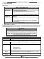
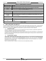
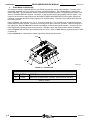
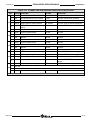
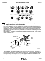
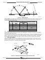
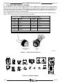
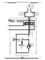
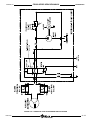
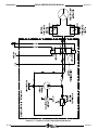
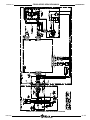
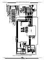
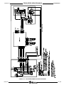
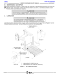
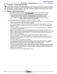
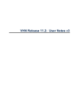
- TABLE OF CONTENTSFEBRUARY 2013 III. FR2SS-SERIES SERVICE MANUAL MAINTENANCE FOLDOVER RAMP MAINTENANCE T he maintenance information in this chapter applies to the Ricon FoldOver Stainless Steel Low-Floor Vehicle Access ramp when installed in transit vehicles. The information consists of safety precautions, a maintenance schedule, component information, and diagrams for the hydraulic and electrical systems. This chapter is intended to supplement related sections of the vehicle manufacturer Owner and Service Manuals. A. GENERAL SAFETY PRECAUTIONS WARNING! THIS RAMP IS DRIVEN WITH HYDRAULIC PRESSURE GENERATED BY A HYDRAULIC PUMP SYSTEM. THE FLUID IS HIGHLY PRESSURIZED AND POSSIBLY VERY HOT. USE EXTREME CAUTION WHEN DOING MAINTENANCE AND REPAIRS. DO NOT DISCONNECT HOSES OR FITTINGS WHEN RAMP IS IN MOTION. Follow these safety precautions during service of the Ricon FoldOver ramp: • Under no circumstances is maintenance, repair, or adjustment of the FoldOver ramp to be performed without the presence of an individual capable of giving aid. • Give immediate attention to all injuries, and administer first-aid or seek medical attention as necessary. • Protective eye shields and clothing should be worn during maintenance, repair, and adjustment of the FoldOver ramp. • The user must be cautious when operating the ramp. Be certain that hands, feet, legs, and clothing are not in the path of ramp movement. • Batteries contain acid that can burn. Wear protective clothing and eye protection at all times. If acid comes in contact with skin, immediately flush affected area with water and wash with soap. Do not place anything electrically conductive on top of battery. Do not smoke or use an open flame near battery. • Work in a properly ventilated area. • Read and understand all instructions before attempting to operate the FoldOver ramp. • Inspect the ramp before use for unsafe conditions, unusual noises, or erratic movements. Do not use ramp if any of these are present, and arrange to have an authorized Ricon dealer or qualified service technician inspect ramp. • Keep others clear of the ramp while it is operating. • Ricon strongly recommends that the vehicle be parked on level ground when using ramp. Using the ramp when vehicle is sloped may result in a ramp angle that is too steep for safe use. In addition, the sloped vehicle may not allow the ramp to make complete contact with the ground. • The FoldOver ramp and other system components require periodic maintenance. Ricon recommends a thorough vehicle inspection by an authorized Ricon dealer or qualified service technician at least once every six months. To maximize safety, the ramp and related components should be maintained at their highest level of performance. • Read and comply with warning labels attached to ramp. 32DFR108.B.4 3-1 FR2SS-SERIES SERVICE MANUAL MAINTENANCE B. FEBRUARY 2013 DAILY INSPECTION Check ramp daily, following the Daily Inspection outlined in Table 3-1. Meet all inspection criteria before allowing passengers on ramp. TABLE 3-1: DAILY INSPECTION INSPECTION POINT CHECK Ramp controller Power ON/OFF switch operates correctly. Power On indicator illuminates when Power ON/OFF switch is ON. DEPLOY and STOW switches operate correctly. No unusual noises or erratic movements when ramp is deploying or stowing. Ramp and surrounding area Vestibule area is free of loose objects, actuator drive arms and trim pockets are free of debris. Ramp non-slip surfaces Surface is clean and free of slippery or sticky substances that could compromise user safety. Surface is intact and secure, and loose edges, if present, cannot create a stumbling hazard. END OF TABLE C. MAINTENANCE SCHEDULE Regular maintenance and inspection of the Ricon FoldOver ramp provides optimum performance and reduces the need for repairs. Maintain the ramp as directed in Table 3-2. Perform ramp maintenance more frequently during heavy use (more than 20 cycles per day). CAUTION! ~ This Ricon Product Is Complex ~ Required warranty period maintenance and repairs must be done at a Ricon authorized dealer or qualified service technician. Improper maintenance, use of non-Ricon replacement parts, or product modification will void warranty and can result in unsafe operating conditions. We recommend that an authorized Ricon dealer or qualified service technician continue maintenance inspections when warranty ends. TABLE 3-2: MAINTENANCE SCHEDULE INSPECTION POINT ACTION – 6,000 MILE INSPECTION – Hydraulic fluid leaks Setscrews Check all hoses and fittings; check fluid level. Tighten, fill, or replace as necessary with Texaco 01554 Aircraft Hydraulic Oil or equivalent U.S. mil spec H5606G fluid. Check for loose or missing setscrews at these locations: Driveshaft couplers (2 x 4 ea) Sensor target (1 ea) Pillow blocks (2 x 2 ea) Tighten, or replace, as necessary. Drive arm T-nuts Ramp interior (for debris) 3-2 Check for looseness; tighten as necessary; apply thread locker (Loc-tite blue), as necessary. Refer to Figure 3-4 for drive arm hardware configuration. Check area below floor plate, and remove any accumulated dirt or debris. 32DFR108.B.4 FR2SS-SERIES SERVICE MANUAL FEBRUARY 2013 MAINTENANCE TABLE 3-2: MAINTENANCE SCHEDULE INSPECTION POINT Non-slip surface Decals ACTION Visually check for damage to surface, and for loose or missing non-slip material. Visually check for illegibility or damage, replace as necessary. – 12,000 MILE INSPECTION – Wiring harnesses Fasteners Non-slip surfaces Check wiring insulation for heavy abrasions, and connectors for looseness. Replace as necessary. Check all threaded fasteners for tightness and retighten as necessary. Check non-slip surface for excessive wear or damage (rips, tears, peeling, etc.), and replace as necessary. – 24,000 MILE INSPECTION – Pillow blocks Bushing & thrust washer Lightly grease pillow blocks. Pillow blocks are sealed; lubricate through grease fitting. Refer to Figure 3-4. Check these hardware parts for excessive play, and replace if necessary. END OF TABLE D. RAMP COMPONENT INFORMATION The Ricon FoldOver Ramp uses electrical power from the host vehicle to deploy and stow the ramp. Vehicle electrical power is converted to hydraulic force, which is used to move the ramp. Electrical and hydraulic components are described below. Please refer to Figures 3-7, 3-8, and 3-9 for hydraulic schematics and flow diagrams. 1. HYDRAULIC PUMP The ramp employs an electro-hydraulic pump (contained within the ramp enclosure) to pressurize hydraulic fluid. Pressure is regulated in the pump body and is preset at Ricon. The hydraulic pump provides pressure to the rotary hydraulic actuator when either the DEPLOY or STOW switch is activated. Ricon recommends operating the ramp while the vehicle engine is running in order to minimize current drain on the vehicle battery. 2. FLOW CONTROL VALVES Two manually adjusted flow control valves (needle valves) control the volume of hydraulic fluid passing through the rotary actuator. Their adjustment determines the rate of ramp movement. There is one valve for ramp deployment and one for stowing. Turning the valves counterclockwise increases the rate of ramp movement, and clockwise decreases the rate of ramp movement. The typical adjustment range for each valve is between ½ to 1 turn open (CCW) from fully closed (fully CW). Refer to Installation Notes in Chapter II for a flow control valve adjustment procedure. 32DFR108.B.4 3-3 FR2SS-SERIES SERVICE MANUAL MAINTENANCE FEBRUARY 2013 3. ELECTRONIC CONTROLLER The electronic controller interprets DEPLOY and STOW requests and controls ramp functions. It contains a programmable integrated circuit (IC), relays, two fuses, and associated parts. The programmable IC cannot be accessed externally. The ramp harness, which is connected to controller connector J1, supplies system power in addition to STOW and DEPLOY requests. Connector J1 also provides positive and negative interlock signals. Connectors J2 and J3 receive signal inputs from the RAMP STOWED and RAMP DEPLOYED sensors, respectively. Connector J4 provides directional control signals to the hydraulic pump. Connector J5 provides a timing signal to the auxiliary counter. Refer to Figure 3-1 for locations of J1, J2, J3, J4, and J5 connectors. The controller cover is sealed with silicone rubber and is not easily removed. Note the four mounting holes at the corners of enclosure. Note fuse location at top, right corner. Refer to Table 3-3 for functions and ratings of fuses located inside controller. Access to the controller is gained by removing bottom cover from ramp. Reseal the cover with silicone rubber before reinstalling. Refer to Figure 3-3 for connector pin numbering and wire colors. Refer to Table 3-4 for a signal description of each connector pin. Refer to Section 4 for a description of sensor light activity during ramp movement. FUSE J4 LED J3 J2 J5 J1 RSM0008200 FIGURE 3-1: CONTROLLER TABLE 3-3: CONTROLLER FUSES FUSE RATING CIRCUIT F2 7.5 AMP Main Power (Programmable Controller, Solenoid Valves, Sensors) END OF TABLE 3-4 32DFR108.B.4 FR2SS-SERIES SERVICE MANUAL FEBRUARY 2013 MAINTENANCE TABLE 3-4: CONNECTOR-PIN DESCRIPTIONS FOR CONTROLLER PIN J1 COLOR FUNCTION AT REST IN ACTION 1 White Output signal to vehicle interlock Ground; stowed No signal; ramp not stowed 2 Red STOW request from control switch 0 volts 24 volts; STOW switch activated 3 Green Ground Ground Ground 4 Orange Output signal to vehicle interlock Off; stowed 24 volts; ramp not stowed (deployed) Black DEPLOY request from control switch 0 volts 24 volts; DEPLOY switch activated 6 Blue 24 volts to controller (constant) 24 volts 24 volts 1 Brown Power to stowed sensor 24 volts 24 volts 2 Not used 3 Blue Ground Ground Ground 4 Black Stowed sensor controller input 0 volts; sensor off 24 volts when sensor is activated 1 Brown Power to deploy sensor 24 volts 24 volts 2 Not used 3 Blue Ground Ground Ground 4 Black Deployed sensor controller input 0 volts 24 volts when sensor is activated 1 Black DEPLOY output to hydraulic pump 0 volts 24 volts; DEPLOY function engaged 2 White STOW output to hydraulic pump 0 volts 24 volts; STOW function engaged 3 Red Ground Ground Ground Green Output to hydraulic pump relay 0 volts 24 volts; STOW/DEPLOY function engaged 1 Brown Output signal to auxiliary counter Off 24V pulse each stow cycle 2 Not used 3 Not used 4 Black Ground for auxiliary counter Ground Ground 5 J2 J3 J4 4 J5 END OF TABLE 32DFR108.B.4 3-5 MAINTENANCE FR2SS-SERIES SERVICE MANUAL FEBRUARY 2013 RSM0008300 FIGURE 3-3: CONTROLLER CONNECTOR-PIN NUMBERING NOTE: Some applications require 12 VDC system power. Voltage levels are 12 volts in these applications. 4. SENSOR LIGHT ACTIVITY DURING RAMP MOVEMENT The latest FoldOver ramps have a third ramp position that is monitored by the controller. This position is very near the to the fully stowed position. The ramp must be within this area before the electrical interlock output signal will turn on (12VDC). This is done to reduce the possibility of a passenger tripping on the front edge of the ramp when it is not stowed competely. Failure to stow completely could be caused by accumulated debris beneath the ramp (within the frame). The following information will provide an aide to troubleshoot ramp problems using the indicator lights on each sensor. Refer to Figure 3-4. This illustration shows the location of the target (installed on a driveshaft), the stow and deploy sensors, and the sensor lights. DEPLOY SEGMENT DEPLOY SENSOR STOW SEGMENT SENSOR LIGHTS STOW SENSOR SENSOR TARGET RSM0008400 FIGURE 3-4: TARGET AND SENSOR LOCATIONS Refer to Figure 3-5. This illustration shows the four ramp positions detected by the controller. The controller determines the ramp angles shown by using the signals from the two sensors. The “A” ramp angle shown in the figure is greater than actual for clarity; the actual height of the front edge of the ramp above the floor is about one inch. This angle can be adjusted by turning the sensor target very slightly. 3-6 32DFR108.B.4 FR2SS-SERIES SERVICE MANUAL FEBRUARY 2013 MAINTENANCE VEHICLE FLOOR RSM0008500 FIGURE 3-5: RAMP POSITIONS Refer to Table 3-5. The status of the sensor lights (on or off) and the interlock output (0VDC or 12VDC) occur over the entire range of each angle shown. Note that the interlock output has both a normal and an inverted output. This table applies to the normal output. TABLE 3-5: SENSOR LIGHT AND INTERLOCK OUTPUT STATUS ANGLE DEPLOY LIGHT STOW LIGHT INTERLOCK OUTPUT A OFF OFF 24VDC B ON OFF 0VDC C ON ON 0VDC D OFF ON 0VDC End of Table 5. CIRCUIT BREAKERS AND FUSES The bus builder installs a 50-amp circuit breaker for 24V applications or a 90-amp circuit breaker for 12V applications to protect ramp control circuits. Two fuses protect the controller, and are located inside its sealed enclosure. Please refer to Figure 3-2 for their locations. The fuses must be replaced by a Ricon authorized dealer or qualified service technician. The hydraulic pump assembly contains an 8-amp circuit breaker to protect components within the hydraulic pump assembly. 6. RAMP ARM ASSEMBLY Please refer to Figure 3-6 for the correct configuration of the arms and their hardware. Use a spanner wrench (Ricon p/n 36250) to tighten the T-nuts that bolt the ramp arms and hardware together. Apply a small amount of threadlocker (Loctite blue) to T-nuts before assembling hardware. RIGHT SIDE SPANNER WRENCH DRIVE ARM DRIVEN ARM THRUST WASHER BUSHING T-NUT SIDE BARRIER RSM0008600 FIGURE 3-6: HARDWARE CONFIGURATION FOR RIGHT SIDE RAMP ARM 32DFR108.B.4 3-7 FR2SS-SERIES SERVICE MANUAL MAINTENANCE E. FEBRUARY 2013 ELECTRICAL AND HYDRAULIC DIAGRAMS Refer to Table 3-6 for wire color codes used on schematic. Refer to Figure 3-7 for a description of plug and receptacle designations used on schematic. Refer to Figure 3-8 for a list of symbols used on schematic. Refer to Table 3-7 for an explanation of labels used on schematic. Refer to Figures 3-9, 3-10, and 3-11 for diagrams of the ramp hydraulic system in its inactive, deploy, and stow modes. The diagrams show the direction and path of fluid flow, and valve positions. The diagrams are located on the following pages. Refer to Figure 3-12 for an overall electrical schematic of the ramp system, including that portion supplied by the bus builder. The electrical schematic is located at the end of this chapter. TABLE 3-6: WIRE COLOR CODES CODE COLOR CODE COLOR BLK BLACK RED RED BLU BLUE TAN TAN BRN BROWN VIO VIOLET GRN GREEN WHT WHITE GRY GRAY YEL YELLOW ORG ORANGE END OF TABLE RECEPTACLE (R) PLUG (P) RSM0008700 FIGURE 3-7: CONNECTOR CONFIGURATION RSM0008800 FIGURE 3-8: SCHEMATIC SYMBOLS 3-8 32DFR108.B.4 FEBRUARY 2013 FR2SS-SERIES SERVICE MANUAL MAINTENANCE TABLE 3-7: WIRING DIAGRAM LABELS LABEL DESCRIPTION +24 VDC System power for interlocks, hydraulic valves, controller, and sensors. NOTE: Some applications require +12 VDC system power. COUNTER Signal; pulse to auxiliary counter; generated by STOW function. DEPLOY Signal; to controller to request DEPLOY function. DEPLOY VALVE INPUT Signal; opens deploy valve. COM, COMMON System electrical common. HEATER MAT Power to ramp heater mat. NOTE: This feature is optional and may not be connected. INTERLOCK Signal; to vehicle interlock circuit when ramp is fully stowed; 24V when ramp is stowed; signal is generated by the electronic controller. INTERLOCK NEG Electrical ground (common) for vehicle interlock systems when ramp stowed; open when ramp is deployed. PUMP SOLENOID INPUT Signal; actuates pump solenoid. SENSOR GROUND Constant ground from controller. STOW Signal; to controller to request STOW function. SENSOR OUTPUT Signal; generated when either the STOWED or DEPLOYED sensor is triggered. STOW VALVE INPUT Signal; opens stow valve. VEHICLE AUDIO ALERT Signal to audible alarm. NOTE: This feature is optional and may not be connected. END OF TABLE 32DFR108.B.4 3-9 ROTARY ACTUATO R FLO W CONTROL VA L V E C1 C2 F LO W C O N TR O L VA L V E A 3 1 D E PLO Y S1 B S TO W S2 W HT B LK D IR E C T IO N A L VALVE G EA R PUM P R E S E R V O IR P R E S S UR E R E L IE F VA LVE 0 VDC PUM P M O TOR H Y D R A U L IC P U M P A SS Y 32DFR108.B.4 3 - 10 FEBRUARY 2013 FR2SS-SERIES SERVICE MANUAL MAINTENANCE FIGURE 3-9: NO HYDRAULIC FLOW AT REST R ED R ED FEBRUARY 2013 FR2SS-SERIES SERVICE MANUAL MAINTENANCE FIGURE 3-10: HYDRAULIC FLUID FLOW DURING DEPLOY MOTION 32DFR108.B.4 3 - 11 MAINTENANCE FR2SS-SERIES SERVICE MANUAL FEBRUARY 2013 FIGURE 3-11: HYDRAULIC FLUID FLOW DURING STOW MOTION 3 - 12 32DFR108.B.4 FEBRUARY 2013 FR2SS-SERIES SERVICE MANUAL MAINTENANCE 50A FIGURE 3-12: FR2SS-SERIES RAMP ELECTRICAL DIAGRAM 32DFR108.B.4 3 - 13 MAINTENANCE FR2SS-SERIES SERVICE MANUAL FEBRUARY 2013 FIGURE 3-13: FR2N-SERIES RAMP ELECTRICAL DIAGRAM 3 - 14 32DFR108.B.4 FEBRUARY 2013 FR2SS-SERIES SERVICE MANUAL MAINTENANCE FIGURE 3-14: FR2G-SERIES RAMP ELECTRICAL DIAGRAM 32DFR108.B.4 3 - 15 MAINTENANCE FR2SS-SERIES SERVICE MANUAL FEBRUARY 2013 This page intentionally left blank. -BACK TO TOP- 3 - 16 -PRINT CHAPTER- - NEXT CHAPTER32DFR108.B.4