1
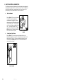
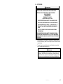
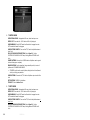
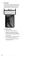
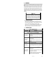
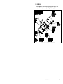
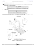
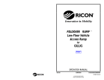
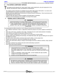
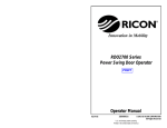
® INNOVATION IN MOBILITY ™ Eclipse F8100 Series Export Use Wheelchair and Standee Lift PRINT Operator Manual 12/03/01 32DF81E01.A U.S. Patent No: 5,253,973 GB(U.K.) Patent No: 2,224,992 Other U.S. and foreign patents pending. Printed in the United States of America 1999-2001 RICON CORP. All Rights Reserved This RICON product must be installed and serviced by authorized RICON service technicians. The operator must refer to this manual for operating instructions, then retain it for future reference. Customer Name: Installing Dealer: Date Installed: Serial Number: 32DF81E01.A i Revision Record REV PAGES 32DF81E01. A All DESCRIPTION OF CHANGE New release in two-book format END OF LIST ii 32DF81E01.A ECR/ECO 3802/4820 TABLE OF CONTENTS Chapter: I. Page INTRODUCTION .....................................................................................1-1 A. RICON 1-YEAR LIMITED WARRANTY..................................................... 1-1 B. SHIPMENT INFORMATION ..................................................................... 1-3 C. GENERAL SAFETY PRECAUTIONS ......................................................... 1-3 D. MAJOR LIFT COMPONENTS .................................................................. 1-4 II. OPERATING INSTRUCTIONS ..................................................................2-1 A. SAFETY PRECAUTIONS ......................................................................... 2-1 B. DAILY SAFETY CHECK........................................................................... 2-2 C. LIFT FUNCTIONS ................................................................................... 2-2 D. CONTROLS AND INDICATORS............................................................... 2-3 E. 1. CONTROL PENDANT ....................................................................... 2-3 2. ELECTRICAL CONTROLS AND INDICATORS..................................... 2-4 LIFT OPERATION................................................................................... 2-7 1. III. TO ENTER VEHICLE......................................................................... 2-8 2. TO EXIT VEHICLE............................................................................. 2-8 3. TO STOW LIFT................................................................................. 2-9 4. MANUAL OPERATION.................................................................... 2-10 5. EMERGENCY STOW PROCEDURE.................................................. 2-10 MAINTENANCE ......................................................................................3-1 A. MAINTENANCE INFORMATION .............................................................. 3-1 B. MAINTENANCE SCHEDULE ................................................................... 3-1 C. LIFT DECALS ........................................................................................ 3-3 32DF81E01.A iii I. INTRODUCTION T he RICON Eclipse F8100 Series Export Use Wheelchair and Standee Lift provides wheelchair access to vehicles. The patented movement ensures smooth, safe entry and exit and easily lifts up to 660 pounds (300 kilograms). It is designed to be operated by a trained attendant or vehicle driver. The operator uses the control pendant to extend the lift OUT (deploy) and then raise the platform to the vehicle floor height. The user boards the large non-skid platform and the operator uses the control switches to gently lower the platform to the ground. After the user departs, the platform is raised and retracted IN (stowed). The Eclipse is an underfloor lift with a powerful electrical hydraulic pump. The lift also contains a built-in manual backup pump. If the lift loses electrical power, two or more people can raise and/or lower the lift manually. This manual contains operation and maintenance instructions for the lift. It is important to user safety that the lift operator(s) be completely familiar with the Operating Instructions chapter of this manual. Once the lift is installed, it is very important that the lift be properly maintained by following the Ricon recommended cleaning, lubrication, and inspection instructions. If there are questions about this manual, or additional copies are needed, please contact Ricon Product Support at one of the following locations: Ricon Corporation 7900 Nelson Road Panorama City, CA 91402........................................................(818) 267-3000 Outside (818) Area Code .........................................................(800) 322-2884 World Wide Website ......................................................... www.riconcorp.com Ricon U.K. Ltd. Littlemoss Business Park, Littlemoss Road Droylsden, Manchester United Kingdom, M43 7EF ...............................................(+44) 161 301 6000 A. RICON 1 YEAR LIMITED WARRANTY (refer to following page) 32DF81E01.A 1-1 RICON CORPORATION 1-YEAR LIMITED WARRANTY Ricon Corporation (Ricon) warrants to original purchaser of this product that Ricon will repair or replace, at its option, any part that fails due to defective material or workmanship as follows: • Repair or replace parts for a period of one year from date of purchase. A complete list of parts covered by this warranty can be obtained from an authorized Ricon dealer. • Labor costs for specified parts replace under this warranty for a period of one year from date of purchase. A Ricon rate schedule determines the parts covered and labor allowed. If You Need to Return a Product: Return this Ricon product to your installing dealer. Please give as much advance notice as possible and allow a reasonable amount of time for repairs. If You are Traveling: All authorized Ricon dealers honor this warranty. Consult a telephone directory or call our Product Support Department for the name of the nearest authorized Ricon dealer. This Warranty does not Cover: • Malfunction or damage to product parts caused by accident, misuse, lack of proper maintenance, neglect, improper adjustment, modification, alteration, the mechanical condition of vehicle, road hazards, overloading, failure to follow operating instructions, or acts of Nature (i.e., weather, lightning, flood). Note: Ricon recommends that this product be inspected by an authorized Ricon service technician at least once every six months, or sooner if necessary. Any required maintenance should be performed at that time. WARNING! THIS PRODUCT HAS BEEN DESIGNED AND MANUFACTURED TO EXACT SPECIFICATIONS. MODIFICATION OF THIS PRODUCT IN ANY RESPECT CAN BE HAZARDOUS. This Warranty is Void if: • The product has been installed or maintained by someone other than an authorized Ricon service technician. • The product has been modified or altered in any respect from its original design without written authorization by Ricon. Ricon disclaims liability for any personal injury or property damage that results from operation of a Ricon product that has been modified from the original Ricon design. No person or company is authorized to change the design of this Ricon product without written authorization by Ricon. Ricon's obligation under this warranty is exclusively limited to the repair or exchange of parts that fail within the applicable warranty period. Ricon assumes no responsibility for expenses or damages, including incidental or consequential damages. Some states do not allow the exclusion or limitation of incidental or consequential damages, so the above limitation or exclusion may not apply. Important: The warranty registration card must be completed and returned to Ricon within 20 days after installation of this Ricon product for the warranty to be valid. The warranty is not transferable. The warranty gives specific legal rights, and there may be other rights that vary from state to state. 1-2 32DF81E01.A B. SHIPMENT INFORMATION Ricon does not sell directly to the user because of the specialized nature of the product. Instead, the product is distributed through the worldwide network of authorized Ricon dealers, who perform the actual sale and installation. • When the product is received, unpack the product and check for freight damage. Claims for any damage should be made to the freight carrier immediately. • Be sure the installation kit contains all items listed on the kit packing list. Please report any missing items immediately to the Ricon Product Support Department. The warranty and owner's registration cards must be completed and returned to Ricon within 20 days for the warranty to be valid. NOTE: The Sales/Service Personnel must review the Warranty and this Operator Manual with the user to be certain that they understand the safe operation of the product. Instruct the user to follow the operating instructions without exception. C. GENERAL SAFETY PRECAUTIONS The following general safety precautions must be followed during installation, operation, service and maintenance: • Under no circumstances should installation, maintenance, repair, and adjustments be attempted without the immediate presence of a person capable of rendering aid. • An injury, no matter how slight, should always be attended. Always administer first aid or seek medical attention immediately. • • Protective eyeshields and appropriate clothing should be worn at all times. To avoid injury, always exercise caution when operating and be certain that hands, feet, legs, and clothing are not in the path of product movement. • Batteries contain acid that can burn. If acid comes in contact with skin, flush affected area with water and wash with soap immediately. • Always work in a properly ventilated area. Do not smoke or use an open flame near a battery. • • Do not lay anything on top of a battery. • Read and thoroughly understand the operating instructions before attempting to operate. • Inspect the product before each use. If an unsafe condition, unusual noises or movements, exists, do not use it until the problem is corrected. • • Keep others clear during operation. Check under vehicle before drilling so as not to drill into frame, subframe members, wiring, hydraulic lines, fuel lines, fuel tank, etc. The product requires regular periodic maintenance. A thorough inspection is recommended at least once every six months. The product must always be maintained at the highest level of performance. 32DF81E01.A 1-3 D. MAJOR LIFT COMPONENTS The references used throughout this manual are illustrated in Figure 1-1 and defined in Table 1-1. Refer to the Service Manual, Chapter IV for more details. FIGURE 1-1: LIFT REFERENCES 1-4 32DF81E01.A TABLE 1-1: F8100 SERIES EXPORT LIFT TERMINOLOGY REF. NAME DESCRIPTION 1 Left 2 Right 3 Front 4 Rear 5 Control Pendant Hand-held device used to control the lift operating functions. 6 Power Unit Electro-hydraulic pump that performs the lift raise/UP and lower/DOWN functions. 7 Lift Enclosure Cassette type structure, rigidly attached to the vehicle, that contains the lift. 8 Carriage Part of traveling frame that contains the necessary components to extend/deploy the lift OUT and retract/stow the lift IN. 9 Lifting Frame Part of the frame that connects the platform to the hydraulic cylinder for raising/UP and lowering/DOWN. 10 Handrail Lock Assembly Manually activated mechanism used to lock the handrail in the upright position. 11 Platform Component where the occupant sits or stands during lift operations. Consists of fixed platform and sliding platform sections. 12 Platform Lock Handle Handle used to lock / or release sliding platform section. 13 Platform Rollstop Front barrier to prevent the wheelchair from slow, inadvertent rolling off the platform during lift operation. 14 Folding Handrails Provide a hand-hold for the platform occupant. 15 Bridgeplate Plate that bridges across the platform and the vehicle threshold. Also serves as a rear rollstop when the platform is at the deployed/OUT and ground level positions. 16 Manual Release Handle Handle used to release the platform for stowing. 17 Deployment Sys- The electrical gear-motor and associated mechanical hardware tem used to extend/deploy the lift OUT and retract/stow the lift IN. Reference points from outside the vehicle looking inward at the platform. END OF TABLE 32DF81E01.A 1-5 II. OPERATING INSTRUCTIONS T his chapter contains safety precautions, daily safety check, lift functions, control and indicator descriptions, and operating instructions for the RICON Eclipse F8100 Series Export Use Wheelchair and Standee Lift. This chapter must be read and thoroughly understood by the operator before attempting to use the lift. A. SAFETY PRECAUTIONS The following safety precautions must be complied with at all times when operating lift: § Refer to Figure 2-1. Deploying lift when vehicle is on sloped ground is dangerous. Always operate lift with vehicle parked on level ground. FIGURE 2-1: UNSAFE VEHICLE SLOPING § Vehicle must be safely parked with the emergency brake ON before using the lift. § Inspect the lift prior to each use. If any unsafe condition exists or unusual noises or movements are noticed, DO NOT use and contact an authorized Ricon dealer for repair. § Read and comply with warning labels and symbols affixed to the wheelchair lift. § When using the lift, the occupant should always FACE OUTWARD. § The platform rollstop is designed to prevent slow inadvertent rolling off the platform. The large rear wheels of a wheelchair can roll over the platform rollstop, so we insist that you always face outward. Hitting the platform rollstop with the small front wheels can tip the wheelchair and possibly injure the wheelchair occupant. Do not expect the rollstop to stop a quick moving wheelchair as it is not designed for that purpose. Use extreme care, board the platform slowly and then lock the wheelchair brakes. § Be certain wheelchair fits safely on the platform and does not extend over the edges of the platform or interfere with operation of the rollstop. § When exiting vehicle NEVER back onto the platform. Always face outward and make sure that the platform is at a safe vehicle floor-level position and the outer rollstop is in an up and locked position. § Do not operate with a load in excess of 660 lbs. (300 kg). § Do not place arms, legs, or clothing in or near moving parts. § The lift is designed for ONE wheelchair and its occupant. Do not overload lift. § Keep others clear while operating. 32DF81E01.A 2-1 § Do not allow an untrained person to operate. § Careful supervision is necessary if used by or near children. § Do not allow anyone to stand on the bridgeplate. Bending this bridgeplate can cause dangerous interference with the platform as it raises or lowers. § Always LOCK WHEELCHAIR BRAKES (power chair users should turn off power and set brake) before lift is operated. § Use extreme care in wet conditions. Wheelchair brakes are less effective if the platform and/or wheelchair wheels are wet. § Never leave platform outside of vehicle. Always return lift to stowed position after use. Be sure that these safety precautions have been read and understood. Review them periodically, and ask any attendants or other operators to read them as well. If there are any questions, contact an authorized Ricon dealer or call Ricon Product Support. B. DAILY SAFETY CHECK Inspect lift before each use and check that following conditions are met before operating: § All functions operate properly. DO NOT use if unusual noises or movements exist, and contact an authorized Ricon Service technician for repair. § Vehicle interlock is operating properly. § No objects that may interfere with operation are present. § General appearance and lubrication are satisfactory and all fasteners are tight. C. LIFT FUNCTIONS For descriptions of the lift functions, refer to Figure 2-2 and Table 2-1. FIGURE 2-2: PLATFORM POSITIONS 2-2 32DF81E01.A TABLE 2-1: LIFT FUNCTIONS FUNCTION DESCRIPTION → OUT ↓ DOWN Platform is lowered from its present position, either vehicle floor level or OUT/deployed position. (The rollstop automatically lowers when the platform reaches ground level.) ↑ UP Platform is raised from its present position, either ground level or OUT/ deployed position. (The rollstop automatically raises when the platform leaves ground level). ← IN Lift retracts/stows from the OUT/deployed position to the IN/stowed position. Lift extends/deploys OUT of the vehicle from the IN/stowed position. END OF TABLE D. CONTROLS AND INDICATORS 1. CONTROL PENDANT Refer to Figure 2-3. The control for the lift is a hand held, hard-wired remote device called the Control Pendant. Control of all lift functions, e.g., raise, lower, in and out, are controlled by this device. The control pendant is mounted inside the vehicle on a wall clip next to the door opening. FIGURE 2-3: CONTROL PENDANT The lift is equipped with a feature that removes electrical power to the lift when it is not in use. The power indicator contained on the control pendant shows when this power is supplied and illuminates only when the lift is in operation. For a further description of the power indicator, refer to Chapter III. NOTE: The power indicator should properly illuminate only when the lift is in operation. If the indicator does not illuminate during operation of the lift or remains illuminated when the lift is not in operation, contact an authorized ricon service technician for repair. NOTE: The ↑/UP and ↓/DOWN functions operate only while the lift is in the deployed position. 32DF81E01.A 2-3 2. ELECTRICAL CONTROLS AND INDICATORS The lift electrical controls and indicators are the circuit breakers that are designed to interrupt electrical power to the lift in case of a short circuit. The circuit breakers are located in the engine/ battery compartment and on the hydraulic power unit (or optional pump enclosure) located inside the vehicle at the rear door. a. Main circuit breaker Refer to Figure 2-4 The main circuit breaker is located in the vehicle engine/battery compartment and is designed to interrupt electrical power to the lift’s electrical system in case of a short circuit. In case of a short circuit, the circuit breaker reset tab will “popdown”. If pressing the reset tab UP and releasing does not reset/restore power, DO NOT press and hold. Contact an authorized Ricon service technician for repair. b. FIGURE 2-4: MAIN CIRCUIT BREAKER Control System Circuit Breaker Refer to Figure 2-5. The control system circuit breaker is found on the hydraulic pump assembly. In case of a control system short circuit, the circuit breaker button will “pop-out”. If pressing and releasing the button does not reset/restore power, DO NOT press and hold. Contact an authorized Ricon service technician for repair. FIGURE 2-5: CONTROL SYSTEM CIRCUIT BREAKER 2-4 32DF81E01.A c. MANUAL BACKUP PUMP Refer to Figure 2-6. The manual backup pump is used to operate the lift if there is no electrical power (the manual backup pump is shown within the standard pump enclosure). The controls for the pump consist of the pump handle extension (installed by the vehicle manufacturer near the pump or stored within the optional pump enclosure cover) for raising the lift platform and the pump release valve for lowering. FIGURE 2-6: STANDARD PUMP ENCLOSURE ? To Raise Platform Manually Refer to Figure 2-7. To raise the platform manually, insert the pump handle extension onto the pump release valve. Make sure the notches at the end of the handle are fully engaged by the release valve pin. Twist the handle CLOCKWISE until lightly-snug to make sure that the pump is in the “raise mode”. Insert the handle extension into pump handle socket and move the handle extension UP and DOWN to raise the platform. FIGURE 2-7: MANUAL PLATFORM RAISING 32DF81E01.A 2-5 ? To Lower Platform Manually WARNING! DO NOT TURN PUMP RELEASE VALVE MORE THAN 1/4-TURN COUNTER-CLOCKWISE. THE VALVE IS TOTALLY REMOVABLE WHICH WILL DISABLE ALL AUTOMATIC AND MANUAL UP/DOWN FUNCTIONS. Refer to Figure 2-8. To lower the platform manually, insert the handle extension onto the pump release valve, and slowly twist the handle 1/4turn COUNTER-CLOCKWISE until the platform begins to lower. Allow the platform to lower to the desired position, and tighten the valve until lightly snug. FIGURE 2-8: MANUAL PLATFORM LOWERING 2-6 32DF81E01.A E. LIFT OPERATION WARNING! IMPROPER USE OF LIFT CAN RESULT IN PERSONAL INJURY. USERS MUST READ AND FOLLOW OPERATING INSTRUCTIONS IN OWNER MANUAL. ADDITIONAL COPIES OF OWNER MANUAL ARE AVAILABLE FROM: RICON CORPORATION 7900 NELSON ROAD PANORAMA CITY, CA 91402 (800) 322-2884 or (818) 267-3000 • DO NOT EXCEED RATED LOAD CAPACITY OF 660 POUNDS (300 KG). • PRIOR TO USE, INSPECT WHEELCHAIR LIFT FOR PROPER FUNCTION, REQUIRED MAINTENANCE, OR DAMAGE. IF A PROBLEM EXISTS, DO NOT USE LIFT, AND CONTACT AN AUTHORIZED RICON DEALER FOR REPAIR. • THIS LIFT IS DESIGNED FOR USE BY WHEELCHAIR AND STANDEE OCCUPANTS ONLY. RICON CORPORATION DISCLAIMS LIABILITY FOR DAMAGE OR PERSONAL INJURY RESULTING FROM MODIFICATION TO LIFT, LACK OF MAINTENANCE OR REPAIR, NEGLIGENCE, ABUSE, OR FAILURE TO FOLLOW LIFT OPERATING INSTRUCTIONS. § Before operating lift, be certain vehicle is safely parked on a level area away from traffic with the emergency brake ON. Allow enough space for lift operation and passenger boarding. § Take special care to ensure that the area is clear of obstacles and open vehicle door(s) completely before deploying the lift. CAUTION! Attendant should always remain near passenger to render immediate assistance if necessary. Keep others clear of lift when operating. Maintain pressure on switch until function is complete. Be certain wheelchair fits properly on platform and does not contact rollstop and prevent it from locking as the platform rises. 32DF81E01.A 2-7 FIGURE 2-9: PLATFORM LOCK HANDLE 1. TO ENTER VEHICLE OPEN OPTIONAL COVER: If equipped with lift cover, unlatch and open cover. DEPLOY LIFT: Press and hold →/OUT switch until lift is fully deployed. RAISE HANDRAILS: Raise RIGHT handrail until handrail lock engages then raise LEFT handrail until handrail lock engages. RAISE PLATFORM SLIGHTLY: Press and hold ↑/UP switch until platform raises at least 1-inch. PULL-OUT SLIDING PLATFORM SECTION: Refer to Figure 2-9. Position PLATFORM LOCK HANDLE to RIGHT and pull sliding platform OUTWARD until it locks. LOWER PLATFORM: Press and hold ↓/DOWN switch until platform reaches ground level and rollstop opens completely. BOARD PLATFORM: Position wheelchair, facing outward if possible, in center of platform and LOCK WHEELCHAIR BRAKES. • STANDEES should stand in center of platform, facing direction of travel (toward vehicle), and firmly grasp handrails. RAISE PLATFORM: Press and hold ↑/UP switch until platform stops at vehicle floor level. EXIT PLATFORM: CAREFULLY exit platform. STOW LIFT: Refer to Section 3 below. 2. TO EXIT VEHICLE OPEN OPTIONAL COVER: If equipped with lift cover, unlatch and open cover. DEPLOY LIFT: Press and hold →/OUT switch until lift is fully deployed. RAISE HANDRAILS: Raise RIGHT handrail until handrail lock engages then raise LEFT handrail until handrail lock engages. RAISE PLATFORM SLIGHTLY: Press and hold ↑/UP switch until platform raises at least 1-inch. PULL-OUT SLIDING PLATFORM SECTION: Refer to Figure 2-9. Position PLATFORM LOCK HANDLE to RIGHT and pull sliding platform OUTWARD until it locks. 2-8 32DF81E01.A RAISE PLATFORM: Press and hold ↑/UP switch until platform stops at proper vehicle floor level. BOARD PLATFORM: Position wheelchair, facing outward if possible, in center of platform and LOCK WHEELCHAIR BRAKES. • STANDEES should stand in center of platform, facing direction of travel (away from vehicle), and firmly grasp handrails. LOWER PLATFORM: Press and hold ↓/DOWN switch until platform reaches ground level and rollstop opens completely. EXIT PLATFORM: CAREFULLY exit platform. STOW LIFT: Refer to Section 3. 3. TO STOW PLATFORM POSITION PLATFORM SLIGHTLY: From vehicle floor level, press and hold ↓/DOWN switch, or from ground level press and hold ↑/UP switch, until platform lowers or raises at least 1-inch. PUSH-IN SLIDING PLATFORM SECTION: Refer to Figure 2-9. Position PLATFORM LOCK HANDLE to RIGHT, raise platform slightly, and push sliding platform INWARD until it locks. POSITION PLATFORM TO STOW LEVEL: Press and hold ↓/DOWN or ↑/UP switch, until platform is positioned at stow level. LOWER HANDRAILS: Release and lower LEFT handrail into stowed position then release and lower RIGHT handrail. STOW LIFT: Press and hold ←/IN switch and red IN-LOCKOUT switch until lift is fully stowed. Lift will raise or lower to proper stowing level and retract into vehicle. CLOSE OPTIONAL COVER: If equipped with lift cover, close and latch cover. 32DF81E01.A 2-9 4. MANUAL OPERATION The manual backup pump is used to operate the lift if there is no electrical power. The controls for the pump consist of the pump handle extension for raising the lift platform and the pump release valve for lowering. In the event the lift becomes inoperable under its electrical power, it can be operated manually as follows: CAUTION! DO not turn pump release valve more than 1/4-turn counter-clockwise. The valve is totally removable which would disable all automatic and manual up/down functions. [3-0]: RELEASE MANUALHANDLE FIGURE FIGURE 2-10: MANUAL a. To Manually Deploy the Platform 2-10 1) If equipped with optional lift cover, unlatch and open cover. 2) At left-side of lift enclosure, pull and hold manual release handle OUTWARD, then pull platform OUTWARD to its fully deployed position. 3) Raise RIGHT handrail until handrail lock engages then raise LEFT handrail until handrail lock engages. 4) Insert handle extension into backup pump handle socket and move pump handle in an UP/DOWN motion to raise platform at least 1-inch. 5) At front of lift, position PLATFORM LOCK HANDLE to RIGHT and pull sliding platform OUTWARD until it locks. 32DF81E01.A b. To Manually Lower or Raise the Platform ♦ To lower lift: Insert pump handle extension onto backup pump release valve. Make sure notches at end of handle are fully engaged by release valve pin. Slowly twist handle 1/4-turn COUNTER-CLOCKWISE until lift platform begins to lower, allow platform to reach stow level or ground level, then turn handle extension CLOCKWISE to close valve. ♦ To raise lift: Insert handle extension into backup pump handle socket and move pump handle in an UP/DOWN motion to raise platform to stow level or vehicle floor level. c. To Manually Stow the Platform 1) Using backup pump, manually raise or lower platform to about 1-inch above stow level. 2) At front of lift, position PLATFORM LOCK HANDLE to RIGHT and push sliding platform INWARD until it locks. 3) Insert pump handle extension onto manual backup pump release valve. Make sure notches at end of handle are fully engaged by release valve pin. Slowly twist handle 1/4-turn COUNTER-CLOCKWISE until lift platform begins to lower, allow platform to stop at stow level, then turn handle extension CLOCKWISE to close valve. 4) Release and lower LEFT handrail into stowed position then release and lower RIGHT handrail. WARNING! TO PREVENT PINCHING FINGERS, PUSH PLATFORM INWARD USING AN OPEN, FLAT HAND AND EXTREME CAUTION. 5. 5) At left-side of lift enclosure, pull and hold manual release handle OUTWARD, then push platform INWARD to its fully stowed position. 6) If equipped with optional lift cover, close and latch cover. EMERGENCY STOW PROCEDURE In the unlikely event there is a hydraulic system failure and the manual backup pump is inoperative, the lift may be stowed as follows by two or more able-bodied people: WARNING! • MANUALLY STOWING OF THIS LIFT REQUIRES FORCES GREATER THAN 100 LBS. DO NOT ATTEMPT TO MANUALLY STOW THE LIFT USING LESS THAN TWO PEOPLE. • THE PLATFORM IS HEAVY AND SHOULD BE LIFTED WITH USING EXTREME CAUTION AND PROPER LIFTING TECHNIQUE: ALWAYS LIFT WITH YOUR LEGS AND NOT YOUR BACK WHEN TO LIFTING HEAVY OBJECTS. 32DF81E01.A 2-11 a. Using ONE PERSON ON EACH SIDE of platform, raise platform until rollstop closes and place temporary support block on each side of lifting frame. b. At front of lift, position PLATFORM LOCK HANDLE to RIGHT and push sliding platform INWARD until it locks. c. Using ONE PERSON ON EACH SIDE of platform, raise platform at least 1-inch above stow level and lower platform to stow level. d. Remove temporary support block. e. Release and lower LEFT handrail into stowed position then release and lower RIGHT handrail. WARNING! TO PREVENT PINCHING FINGERS, PUSH PLATFORM INWARD USING AN OPEN, FLAT HAND AND EXTREME CAUTION. 2-12 f. At left-side of lift enclosure, pull and hold manual release handle OUTWARD, then push platform INWARD to its fully stowed position. g. If equipped with optional lift cover, close and latch cover. 32DF81E01.A III. MAINTENANCE R outine maintenance of the RICON Eclipse F8100 Series Export Use Wheelchair and Standee Lift will optimize its performance and reduce the need for repairs. Maintenance inspections must be performed by an authorized Ricon service technician at least once every six months or sooner, depending on usage. Maintenance inspections are required at least every six months and a thorough maintenance inspection should be performed at the service intervals referenced in Table 3-1. Under conditions of excessive use (more than 10 cycles per day), service should be increased. CAUTION! This Ricon product is highly specialized. Maintenance and repairs must be performed only by an authorized Ricon service technician using only Ricon replacement parts. Modifying or failing to properly maintain this product will void warranty and may result in unsafe operating conditions. A. MAINTENANCE INFORMATION Additional maintenance information is available in the Eclipse F8100 Series Export Use Service manual, part number 32DF81E02. This manual is available from Ricon in printed hard copy, or at the Ricon website in PDF format. The website is located at www.riconcorp.com. Click on RICON CORPORATION and then DEALER’S ROOM at the website. Entry to the dealer’s room will require a Dealer Number and a Password. B. MAINTENANCE SCHEDULE TABLE 3-1: MAINTENANCE SCHEDULE SERVICE POINT DESCRIPTION DAILY SAFETY CHECK (or @ 10 - 20 cycles of operations) General Appearance If any abnormal noises exist, notify an authorized service technician immediately. Inspect underside of vehicle to verify nothing is out of the ordinary. Lift Mountings and Support Points Verify that all lift mounting and support points are in proper order and free from damage. Verify that all mounting bolts are of appropriate grade and sufficiently tight. Carriage Stops Verify carriage stops fasten properly. Main Lifting Pivots Verify carriage/lifting frame/platform pivot pins are installed properly, free from damage and locked in position with proper fasteners. Platform and Platform Attachment Points Verify platform operates properly during lift UP/DOWN functions without obstruction(s). Verify that all welds on carriage brackets, lifting frame and platform mounting brackets are in proper order. Verify that platform mounting brackets are properly fastened to both sides of the platform with the appropriate bolts. 32DF81E01.A 3-1 Bridgeplate and Bridgeplate Operation Verify that bridge plate functions properly during lift UP/DOWN operations without obstruction(s). Verify that the bridgeplate deploys fully as the platform stops at the proper vehicle floor level. Rollstop and Rollstop Operation Verify that rollstop operates properly on contact with the ground. Verify that rollstop opens, closes and locks properly without obstruction(s). Verify that rollstop return springs are in proper order. Handrail and Handrail attachment Verify that all fasteners are present and properly tightened. Verify that latch and load springs function properly. BI-WEEKLY SAFETY CHECK (or @ 140 - 180 cycles of operation) Labeling, Decals, and Cleaning Verify that the Rated Load Capacity decal is affixed properly, clearly visible and legible. Replace if necessary. Verify that all Operating Instruction decals are affixed properly, clearly visible and legible. Replace if necessary. Verify that serial number is clearly marked, legible and visible. After washing vehicle, spray lubricant, such as Curtisol Red Grease #88167, on all carriage/lifting frame/platform/rollstop pivot points, and rub down all surfaces with oil to avoid rusting of material. THREE MONTH SAFETY CHECK (or @ 900 - 1000 cycles of operation) Rollstop Pivot Points Spray lubricant, such as Curtisol Red Grease #88167, on rollstop pivot points. Wipe clean any excess grease from targeted areas and surrounding areas. Platform Guides and Bridgeplate Pivot Points. Spray lubricant, such as Curtisol Red Grease #88167, on sliding platform guide rails and bridgeplate pivot points. Wipe clean any excess grease from targeted areas and surrounding areas. Hydraulic Fluid Level Verify that the hydraulic fluid level is maintained at the required "full" level. Add only Texaco 01554 aircraft hydraulic fluid (or equivalent U.S. mil spec H5606G oil). ANNUAL SAFETY CHECK (or @ 3600 - 4000 cycles of operation) Hydraulic Pump Unit Extract, refill, extract again, and refill the Hydraulic Unit Reservoir to the required "full" line using Texaco 01554 hydraulic fluid. Add only Texaco 01554 aircraft hydraulic fluid (or equivalent U.S. mil spec H5606G oil). Hydraulic Cylinder/Flow Control Valve/Hoses, Lines and Seals If hydraulic fluid is low, inspect the following for evidence of leaks: • Hydraulic Cylinder and Flow Control Valve. • Verify that hydraulic hoses are not damaged. • Verify that all seals are seated properly and all fittings are tightly secured. *RICON CORP. strongly recommends that this lift be refit after five years of use. END OF TABLE 3-2 32DF81E01.A C. LIFT DECALS Refer to Figure 3-1. Inspect for chipping, peeling, fading, and illegibility. Order replacement decals by part number given in Figure 3-1, and apply where shown. FIGURE 3-1: DECAL LOCATIONS AND PART NUMBERS 32DF81E01.A 3-3