1
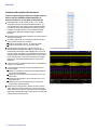
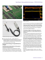
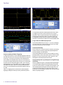
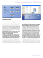
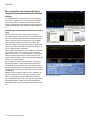
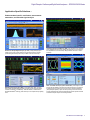
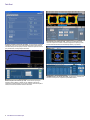
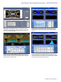
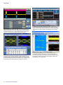
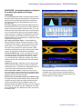
Digital Phosphor Oscilloscopes/Digital Serial Analyzers
DPO/DSA70000B Series Data Sheet
DPX and Fast Acquisition - Quickly find intermittent events with the
industry’s highest waveform capture rate
Long Record Lengths – Capture long-term trends or infrequent events
then analyze the entire acquired record with built-in measurements
P7500 TriMode™ Probing System - Perfectly matched signal
connectivity from 4 GHz to 20 GHz
Application Support – Enables standard-specific certification,
measurement automation, and ease of use
Serial Data Link Analysis (SDLA) - For high-speed serial data streams,
emulate and equalize the channel as well as de-embedding the fixture.
Applications
Signal Integrity, Jitter, and Timing Analysis
Verification, Debug, Characterization, or Certification of Sophisticated
Designs
Features & Benefits
On All Four Channels Simultaneously
20, 16, 12.5, 8, 6, and 4 GHz Bandwidth Models
Up to 50 GS/s Real-Time Sample Rate
Up to 250 Megasamples Record Length with MultiView Zoom™
Feature for Quick Navigation
Fastest Waveform Capture Rate with >300,000 wfms/s Maximum per
Channel
Highest Bandwidth – Up to 20 GHz enables measurement on the latest
high-speed serial standards
Superior Signal Integrity and Excellent Signal-to-Noise Ratio – Observe
the truest representation of your waveform
Pinpoint® Triggering – Minimize time spent trying to acquire problem
signals for efficient troubleshooting and shortened debug time
5 Gbps Real-time Serial Trigger – Assures triggering on the first instance
of a specified NRZ or 8b/10b pattern to allow isolation of pattern
dependent effects
Search & Mark – Provides waveform pattern matching and software
triggers for signals of interest
Debugging and Compliance Testing of Serial Data Streams for Industry
Standards
Memory Bus Analysis
Switching Power Supply Verification
Investigation of Transient Phenomena
Spectral Analysis of Transient or Wide-bandwidth RF Signals
Unmatched Performance for Greater Insight
Gets Your Work Done Faster
The DPO70000B and the DSA70000B Series real-time digital phosphor
oscilloscopes are the industry’s best solution to the challenging signal
integrity issues faced by designers verifying, characterizing, debugging,
and testing sophisticated electronic designs. The specialized DSA70000B
Series provides a complete and dedicated solution to address the
challenges of high-speed serial designs.
The family features exceptional performance in signal acquisition and
analysis, operational simplicity, and unmatched debugging tools to
accelerate your day-to-day tasks. A large display and the intuitive user
interface provide easy access to the maximum amount of information.
Data Sheet
Unmatched Acquisition Performance
Superior Signal Integrity and Excellent Signal-to-Noise
Ratio of the DPO70000B and DSA70000B Series
Ensures Confidence in Your Measurement Results
High bandwidth up to 20 GHz matched across 2, 3, or 4 channels
and enabled by Tektronix proprietary bandwidth enhancement. The
user-selectable filter for each channel provides magnitude and phase
correction for more accurate representation of extremely fast signals.
In addition, only Tektronix allows the user to disable the bandwidth
enhancement for applications needing the highest measurement
throughput.
Bandwidth enhancement eliminates imperfections in frequency response
all the way to the probe tip
Simultaneous high sample rate on all channels captures more signal
details (transients, imperfections, fast edges)
50 GS/s on all channels for the 12.5, 16, and 20 GHz models
25 GS/s on all channels for the 4, 6, and 8 GHz models
With high signal-to-noise ratio and low internal noise floor, the
DPO70000B and DSA70000B series enable you to perform precise
characterization measurements. When debugging a DUT, a low noise
floor and maximum signal fidelity of the measurement instrument allows
finding the smallest anomalies that might affect the DUT’s performance.
For RF signal verification, a lower noise floor translates into a higher
dynamic range, opening the DPO/DSA70000B for a wider range of
applications.
User-selectable bandwidth limiting choices
Lowest jitter noise floor and highest vertical accuracy provide additional
margin in your measurements.
Long record length provides high resolution and extended-duration
waveform capture
Standard 10 M samples per channel on the DPO70000B Series and
20 M on the DSA70000B Series
Optional up to 100 M samples on all four channels for the 4, 6, and
8 GHz models
Optional up to 250 M samples on all four channels for the 12.5, 16,
and 20 GHz models
MultiView Zoom helps you manage long records, compare and
analyze multiple waveform segments
Widest Range of Probing Solutions – Whether you need to measure
8 Gbps serial data or switching currents from your new power supply
design, Tektronix offers a vast array of probing solutions, including active
single ended, differential, high voltage, current, optical, and a wide range
of probe and oscilloscope accessories.
2
www.tektronix.com/oscilloscopes
Zoom in on four areas of interest simultaneously to quickly compare them
Digital Phosphor Oscilloscopes/Digital Serial Analyzers — DPO/DSA70000B Series
Low-cost solder tip features quick connection so moving probe to various solder points is
fast and easy
Maximize the probability of capturing elusive glitches and other infrequent events with
FastAcq acquisition mode.
knob you can clearly “see a world others don’t see”, displaying the complete
picture of your circuit’s operation. Some oscilloscope vendors claim high
waveform capture rates for short bursts of time, but only DPO70000B and
DSA70000B oscilloscopes, enabled by DPX technology, can deliver these
fast waveform capture rates on a sustained basis — saving minutes, hours,
or even days by quickly revealing the nature of faults so sophisticated
trigger modes can be applied to isolate them.
P7500 TriMode probes simplify complex measurement setups
P7500 TriMode probing system – Perfectly matched to the
DPO/DSA70000B, the P7500 TriMode probes allow you to switch among
differential, single ended, and common-mode measurements without
moving the probe from its connection points. The P7500 series offers
probes for performance from 4 GHz to 20 GHz.
Accelerate the Debug of Complex Electrical
Designs
FastAcq Acquisition Mode Expedites Debugging by
Clearly Showing Imperfections
More than just color-grading, FastAcq’s proprietary DPX® acquisition
technology captures signals at more than 300,000 waveforms per second
on all four channels simultaneously, dramatically increasing the probability
of discovering infrequent fault events. And with a simple turn of the intensity
The Ability to Trigger an Oscilloscope on Events of
Interest is Paramount in Complex Signal Debug and
Verification
Whether you’re trying to find a problem signal or need to isolate a section
of a complex signal for further analysis, like a DDR read or write burst.
Tektronix’ Pinpoint® triggering provides the solution. The Pinpoint trigger
system uses Silicon Germanium (SiGe) technology to provide very high
trigger sensitivity with very low trigger jitter and ability to capture very
narrow glitches. Pinpoint triggering allows selection of virtually all trigger
types on both A and B trigger events. Other trigger systems offer multiple
trigger types only on a single event (A event), with delayed trigger (B event)
selection limited to edge type triggering and often do not provide a way
to reset the trigger sequence if the B event doesn’t occur. But Pinpoint
triggering provides the full suite of advanced trigger types on both A and
B triggers, logic qualification to control when to look for these events,
and reset triggering to begin the trigger sequence again after a specified
time, state, or transition so that even events in the most complex signals
can be captured. Other oscilloscopes typically offer less than 20 trigger
combinations; Pinpoint triggering offers over 1400 combinations, all at full
performance.
With Enhanced Triggering, trigger jitter is reduced to <100 fs. With this
stability at the trigger point, the trigger point can be used as a measurement
reference.
www.tektronix.com/oscilloscopes
3
Data Sheet
Pinpoint triggering can isolate glitches down to 100-ps wide
NRZ Pattern Lock Triggering of a 640-bit long SATA serial pattern at 6 Gbps
of a long serial test pattern with outstanding time base accuracy. Pattern
lock triggering can be used to remove random jitter from long serial
data patterns. Effects of specific bit transitions can be investigated, and
averaging can be used with mask testing. This feature supports up to
6.25 Gbps NRZ serial data stream and is standard on the DSA70000B
instruments, or included as part of Option PTH on the DPO70000B models.
Large 10-Division XGA Display Screen
The DPO/DSA70000B Series have a large 12.1” (307.3 mm) XGA display
with a touch screen with 10 vertical divisions give you 25% more vertical
measurement resolution than other oscilloscopes.
Unmatched Usability
Isolate only the valid glitches
Protocol and Serial Pattern Triggering
To debug serial architectures, use the serial pattern triggering for NRZ serial
data stream with built-in clock recovery and correlate events across physical
and link layers. This feature comes standard on the DSA70000B series
and is available on DPO70000B models as Opt. PTH. The instrument can
recover the clock signal, identify transitions, and allow you to set the desired
encoded words for the serial pattern trigger to capture. Opt. PTH and the
DSA70000B Series cover serial standards up to 3.125 Gbps. For higher bit
rate standards like USB 3.0, option PTU on the DPO70000B series and
option STU on the DSA70000B series extend 8b10b triggering and decode
to 5 Gbps.
Pattern Lock Triggering adds an extra dimension to NRZ serial pattern
triggering by enabling the oscilloscope to take synchronized acquisitions
4
www.tektronix.com/oscilloscopes
TekLink™ allows you to acquire more than four channels by synchronizing
multiple oscilloscopes and debug multiple-lane high-speed applications
such as PCI Express X16 or DDR memory.
The DPO/DSA70000B Series instruments excel in usability with a suite of
productivity features, such as a touch screen, flat menu structures, intuitive
graphical icons, knob-per-channel vertical controls, right clicks, mouse
wheel operation, and familiar Windows-based controls.
Interoperability with Logic Analyzers for Digital Design
and Debug
Tektronix’ Integrated View (iView™) data display enables digital designers
to solve signal integrity challenges and effectively debug and verify their
systems more quickly and easily. This integration allows designers to view
time-correlated digital and analog data in the same display window, and
isolate the analog characteristics of the digital signals that are causing
system failures. No user calibration is required. And, once set up, the iView
feature is completely automated.
Digital Phosphor Oscilloscopes/Digital Serial Analyzers — DPO/DSA70000B Series
3 modes of operation of the horizontal time base
Unmatched Versatility
Get the Most of Your Oscilloscope by Fully Controlling
its Waveform Acquisition and Display Parameters.
Choose the operation you need to do your job the fastest: Automatic,
Constant Sample Rate, or Manual. When you are doing signal exploration
and want a lively signal, the default Automatic mode provides you with
the liveliest display update rate. If you want the highest real-time sample
rate that will give you the most measurement accuracy, then the Constant
Sample Rate mode is for you. It will maintain the highest sample rate and
provide the best real-time resolution. Finally the Manual mode ensures
direct and independent control of the sample rate and record length for
applications requiring specific settings.
With the MyScope® Feature, Create Your Own Control
Windows With Only the Controls, Features, and
Capabilities that You Care About
Easily create your own personalized "toolbox" of oscilloscope features
in a matter of minutes using a simple, visual, drag-and-drop process.
Once created, these custom control windows are easily accessed through
a dedicated MyScope button and menu selection on the oscilloscope
button/menu bar, just like any other control window. You can make an
unlimited number of custom control windows, enabling each person who
uses the oscilloscope in a shared environment to have their own unique
control window. MyScope control windows will benefit all oscilloscope
users, eliminating the ramp-up time that many face when returning to the lab
after not using an oscilloscope for a while, and enables the power user to be
Drag and drop menu items of interest to create the MyScope control window
far more efficient. Everything you need is found in one control window rather
than navigating through multiple menus to repeat similar tasks.
With OpenChoice® Software, Customize Your Test and
Measurement System with Familiar Analysis Tools
The analysis and networking features of OpenChoice software add
more flexibility to Tektronix’ Windows XP oscilloscopes: Using the fast
embedded bus, waveform data can be moved directly from acquisition
to analysis applications on the Windows desktop at much faster speeds
than conventional GPIB transfers. Tektronix’ implementation of industry
standard protocols, such as TekVISA™ interface and ActiveX controls, are
included for using and enhancing Windows applications for data analysis
and documentation. IVI instrument drivers are included to enable easy
communication with the oscilloscope using GPIB, RS-232, and LAN
connections from programs running on the instrument or an external PC. Or,
use the Software Developer’s Kit (SDK) to help create custom software
to automate multistep processes in waveform collection and analysis with
Visual BASIC, C, C++, MATLAB, LabVIEW, LabWindows/CVI, and other
common Application Development Environments (ADE). Integration of the
oscilloscope with external PCs and non-Windows hosts is also supported.
In addition, the OpenChoice architecture provides a comprehensive
software infrastructure for faster, more versatile operations. Data transfer
utilities, such as the Excel or Word toolbar plug-ins can be used to simplify
analysis and documentation on the Windows desktop or on an external PC.
www.tektronix.com/oscilloscopes
5
Data Sheet
More Insight into Your Complex Electrical
Design for Characterization and Certification
Testing
The DPO/DSA70000B series offers the industry’s most comprehensive
set of analysis and certification tools, such as a simple math expression,
waveform mask testing, a pass/fail tests, event searching, and event
marking. Custom applications that you develop yourself using application
development environments such as MATLAB® can further extend this tool
set.
A Wide Range of Built-In Advanced Waveform Analysis
Tools
Waveform cursors make it easy to measure trace-to-trace timing
characteristics, while cursors that link between YT and XY display modes
make it easy to investigate phase relationships and Safe Operating Area
violations. Select from 53 automatic measurements using a graphical
palette that logically organizes measurements into Amplitude, Time,
Combination, Histogram, and Communications categories. Gather further
insight into your measurement results with statistical data such as mean,
min, max, standard deviation, and population.
Define and apply math expressions to waveform data for on-screen results
in terms that you can use. Access common waveform math functions
with the touch of a button. Or, for advanced applications, create algebraic
expressions consisting of live waveforms, reference waveforms, math
functions, measurement values, scalars, and user-adjustable variables with
an easy-to-use calculator-style editor.
FFT – To analyze your signal in the frequency domain, use the built-in
spectral analysis function. Using the oscilloscope front-panel controls,
you can directly control the frequency span, center frequency, reference
level, and resolution bandwidth. Vector signal analysis and Ultra-Wideband
(UWB) verification and characterization are provided as part of the SignalVu
and UWB options.
Filtering – Enhance your ability to isolate or remove a component of your
signal (noise or specific harmonics of the signal) by creating your own
filters or by using the filters provided as standard with the instrument.
These customizable FIR filters can be used to implement today’s preferred
signal-filtering techniques, including removing signal pre-emphasis or
minimizing the effects of fixtures and cables connected to the device under
test.
6
www.tektronix.com/oscilloscopes
Capture data into Microsoft Excel using the unique Excel toolbar, and create custom
reports using the Word toolbar
Basic spectral UI control window
Digital Phosphor Oscilloscopes/Digital Serial Analyzers — DPO/DSA70000B Series
Application Specific Solutions –
Enable standard specific certification, measurement
automation, and extended signal analysis
DPOJET Jitter And Eye Diagram Analysis (Opt. DJA) – Simplify identifying signal
integrity concerns, jitter, and their related sources with DPOJET software. DPOJET
provides the highest sensitivity and accuracy available for real-time oscilloscopes.
DDR Memory Bus Analysis (Opt. DDRA) – Automatically identify DDR1, LP-DDR1,
DDR2, DDR3, and GDDR3 Reads and Writes and clearly see and analyze how analog
anomalies are affecting your DDR/Memory. DDRA with DPOJET, combined with the
DPO/DSA70000B DPX® technology, is the fastest way to solve complex memory signaling
issues.
Advanced Event Search and Mark (Opt. ASM) – Ease the tedious task of examining
data by highlighting important events, skipping the unimportant ones, and enhancing
the comprehension of event relationships. Navigate between the events of interest
effortlessly.
SDLA - Serial Data Link Analysis (options SLE and SLA) – Gain insight into serial
data links with the capability to emulate the serial data channel from its S-parameters,
de-embed the fixture or other network, and add or remove transmitter equalization
(de-emphasis/pre-emphasis). Option SLA adds processing of waveforms with FFE
and DFE equalizations and automatic equalizer training. DPOJET provides advanced
measurement and jitter analysis of the resulting waveforms.
www.tektronix.com/oscilloscopes
7
Data Sheet
DisplayPort Compliance Test Solution (Opt. DSPT) – Support DisplayPort Compliance
Test Standard (CTS) source test with four-line simultaneous testing using the Tektronix
P7300SMA Series probes and DisplayPort software. Detailed test reports with waveform
plots, pass/fail results, and margin analysis are included.
DVI Compliance Test Solution (Opt. DVI) – Obtain quick and dependable results
with the DVI compliance test software. Automated testing based on objective pass/fail
detection without human intervention will dramatically enhance your productivity.
FB-DIMM Compliance Test Solution (Opt. FBD) – Test the Receiver, Transmitter, and
Reference clock test points for compliance as per FB-DIMM standards.
Ethernet Compliance Test Solution (Opt. ET3) – Receive full PHY layer support
for Ethernet variants 10BASE-T, 100BASE-TX, and 1000BASE-T with Tektronix’
comprehensive, integrated Ethernet tool set. Analog verification, automated compliance
software, and device characterization solutions are all included.
8
www.tektronix.com/oscilloscopes
Digital Phosphor Oscilloscopes/Digital Serial Analyzers — DPO/DSA70000B Series
HDMI Compliance Test Solution (Opt. HT3) – Fast, efficient solution for HDMI
compliance measurement challenges, no matter if you are working on a Source, Cable,
or Sink solution. This application provides all the HDMI compliance test solutions you
need to ensure quality and interoperability.
PCI Express Analysis Test Solution (Opt. PCE) – Analyze the performance of your
PCI-Express Rev 1.0, 2.0, or 3.0 (draft spec) design with comprehensive test support.
Option PCE enables tests that conform to PCI-SIG standards using either DPOJET
or RT-Eye.
Power Measurement and Analysis Software (Opt. PWR) – Improve the efficiency of
switching power supplies with increased power densities. Measure and analyze power
dissipation in power supply switching devices and magnetic components, and generate
detailed test reports in customizable formats.
TekExpress™ SATA Automated Compliance Test Software – Reduce your compliance
test time by approximately 70% with the simple, efficient testing and automation of all
required testing suites provided by TekExpress software. Also included is auto-recognition
of all required test equipment, precise DUT/Host control one-button testing, and complete
support for SATA Gen1 and SATA Gen2 defined test suites.
www.tektronix.com/oscilloscopes
9
Data Sheet
USB 2.0 Compliance Test Solution (Opt. USB) – Ensure your design has sufficient
margins by characterizing your device with variable test limits. The USB compliance
test solution provides “one touch” compliance testing by automatically setting up the
oscilloscope for all compliance test configurations including probe deskew.
USB 3.0 Transmitter Testing – Verify, debug, and certify to the specifications of
the USB 3.0 PHY layer using native capabilities in and additional applications for the
DPO/DSA70000B series. Math function FIR filters and SDLA software, allow emulation
of the Cable and Reference channels defined in the USB 3.0 spec. With DPOJET, jitter
measurements needed to complete the Normative compliance test can be done.
10
www.tektronix.com/oscilloscopes
Ultra-Wideband Spectral Analysis Software (Opt. UWB) – Analyze hundreds of packet,
TFC, and data-rate combinations without adjusting the UI. In addition, the automatic
WiMedia modulation analysis configuration will analyze how complex wideband signals
change frequency and amplitude with time using real-time spectrograms spanning
20 GHz.
SignalVu™ Vector Signal Analysis – Easily verify wide-bandwidth designs such
as wideband radar, high data rate satellite links, or frequency-hopping radios and
characterize wideband spectral events. SignalVu combines the functionality of a vector
signal analyzer, a spectrum analyzer, and the powerful triggering capabilities of the
DPO/DSA70000B – all in a single package.
Digital Phosphor Oscilloscopes/Digital Serial Analyzers — DPO/DSA70000B Series
DSA70000B – A dedicated solution configured
for today’s high-speed serial design
challenges
The DSA70000B Digital Serial Analyzer is specially configured to address
high-speed serial data designs by encapsulating many of the serial domain
features needed for high-speed serial verification and characterization.
These standard features on the DSA70000B Series are options on the
DPO70000B series.
Serial Pattern Triggering – Real-time serial pattern triggering and protocol
decode with built-in clock recovery recovers the clock signal, identifies the
transitions, and decodes characters and other protocol data. You can see
the 8b/10b bit sequences decoded into their words for convenient analysis,
or you can set the desired encoded words for the serial pattern trigger to
capture. With Pattern Lock Triggering, the DSA70000B can synchronize to
long serial test patterns up to 6.25 Gbps and remove random jitter. The
DSA70000B Series covers serial standards up to 3.125 Gbps with an option
to support up to 5 Gbps (Opt. STU)
Jitter, Timing, and Eye-diagram Analysis – The DSA70000B Series
features the highest-accuracy jitter and timing measurements as well as
comprehensive analysis algorithms. Tight timing margins demand stable,
low-jitter designs. You can make jitter measurements over contiguous
clock cycles on every valid pulse in a single-shot acquisition. Multiple
measurements and trend plots quickly show system timing under variable
conditions, including Random and Deterministic Jitter separation.
Communications Mask Testing – Provides a complete portfolio of masks
for verifying compliance to serial communications standards. 156 masks
for the following standards are supported – PCI Express, ITU-T/ANSI
T1.102, Ethernet IEEE 802.3, ANSI X3.263, Sonet/SDH, Fiber Channel,
InfiniBand, USB, Serial ATA, Serial Attached SCSI, IEEE 1394b, RapidIO,
OIF Standards.
20 MSample Record Length – 20 Msamples on all four channels provides
a longer time sequence at high resolution. Optional record lengths up to
100 Msamples for the 4, 6, and 8 GHz models, 250 Msamples for the 12.5,
16, and 20 GHz models extend the acquisition time sequence.
Advanced Event Search and Mark – Finding important events such as
fast or slow transitions, setup and hold violations, or logic patterns within a
long-duration capture is made easy with the pattern matching and software
triggering functionality of Event Search and Mark.
Accurate, Simple, and Customizable Physical Layer Certification Testing –
Jitter, Timing, and Eye-diagram Analysis
Communications Mask Testing
With standard features that extend the functionality of the Tektronix
DPO70000B series to address high-speed serial signal analysis and
certification, the DSA70000B series offers a specialized instrument that
efficiently addresses your design challenges.
For designers with industry-standard certification needs, standard-specific
compliance and analysis modules that configure the pass/fail waveform
mask and measurement limit testing are available as options to the
DSA70000B. Modules are available for PCI Express (Opt. PCE), Serial ATA
and SAS (Opt. SST), FB-DIMM, (Opt. FBD), InfiniBand (Opt. IBA), HDMI
(Opt. HT3), Ethernet (Opt. ET3), DisplayPort (Opt. DSPT), DVI (Opt. DVI),
and USB (Opt. USB).
www.tektronix.com/oscilloscopes
11
Data Sheet
Characteristics
Vertical System
DPO/DSA Models
Bandwidth (user
selectable DSP
enhance)
Hardware Analog
Bandwidth (-3 dB)
Input Channels
Rise Time 10% to 90%
(typical)
Rise Time 20% to 80%
(typical)
Vertical Noise (% of full
scale) (typical)*16
Bandwidth Limits
Channel-to-channel
Isolation (Any Two
Channels at Equal
Vertical Scale Settings)
DC Gain Accuracy
Delay between any two
channels (typical)
Effective Number of
Bits (typical)
Input Coupling
Input Impedance
Input Sensitivity
18 GHz and below
20 GHz and 19 GHz
Max Input Voltage,
50 Ω
Offset Accuracy
70404B
70604B
70804B
71254B
71604B
72004B
4 GHz
6 GHz
8 GHz
12.5 GHz
16 GHz
20 GHz
4 GHz
6 GHz
8 GHz
12.5 GHz
16 GHz (typical)
16 GHz (typical)
4
98 ps
4
65 ps
4
49 ps
4
32 ps
4
24.5 ps
4
19 ps
68 ps
45 ps
34 ps
22 ps
17 ps
14 ps
0.28%
0.32%
0.35%
0.38%
0.43%
0.77%
Depending on instrument model: 19 GHz, 18 GHz, 17 GHz, 16 GHz, 15 GHz, 14 GHz, 13 GHz, 12 GHz, 11 GHz, 10 GHz,
9 GHz, 8 GHz, 7 GHz, 6 GHz, 5 GHz, 4 GHz, 3 GHz, 2 GHz, 1 GHz, or 500 MHz
≥120:1 (for input frequency 0 to 10 GHz)
≥80:1 (for input frequency >10 GHz to 12 GHz.
≥50:1 (for input frequency >12 GHz to 15 GHz)
≥25:1 (for input frequency >15 GHz)
±2% (of reading)
≤100 ps for any two channels with equal V/div and coupling settings
≤50 ps with BW enhance enabled (BW+)
5.4 bits*14
Offset Range
Passband Flatness (20,
50, 100, 250 mV/div)
(typical)
Position Range
Vertical Resolution
DC (50 Ω), GND
50 Ω ±2%, 1 MΩ with TCA-1MEG adapter
10 mV/div to 500 mV/div (100 mV to 5 V full scale)
20 to 500 mV/div (200 mV to 5 V full scale)
<5.0 VRMS for ≥100 mV/div; also determined by TekConnect accessory
1.0 VRMS for <100 mV/div
10 mV/div – 99.5 mV/div. ±(0.35% (offset value-position) + 1.5 mV + 1% of full scale)
100 mV/div – 500 mV/div. ±(0.35% (offset value-position) + 7.5 mV + 1% of full scale)
10 mV/div: ±450 mV
20 mV/div: ±400 mV
50 mV/div: ±250 mV
100 mV/div: ±2.0 V
200 mV/div: ±1.5 V
500 mV/div: ±0.0 V
±0.5 dB to 50% of nominal bandwidth at 25 °C
*14 50 mV/div, bandwidth filter on, max bandwidth up to 13 GHz, max sample rate
*16 50 mV/div, bandwidth filter on
12
www.tektronix.com/oscilloscopes
±5 div
8 bit (11 bit with averaging)
Digital Phosphor Oscilloscopes/Digital Serial Analyzers — DPO/DSA70000B Series
Time Base System
70404B
DPO/DSA Models
Time Base Range
Time Resolution (in
ET/IT mode)
Channel-to-channel
Deskew
Delta Time
Measurement
Accuracy RMS
Over <100 ns duration;
single shot; with signal
rise time = 1.2X scope
rise time
Jitter Noise Floor
(typical)
(With BW+ bandwidth
enhance enabled)
Time Base Accuracy
Time Base Delay
Time Range
Trigger Jitter (RMS)
70604B
70804B
71254B
20 ps/div to 1000 s/div
200 fs
71604B
72004B
10 ps/div to 1000 s/div
100 fs
Range ±75 ns
1.61 ps
1.29 ps
1.14 ps
940 fs
900 fs
1.02 ps
450 fs
450 fs
450 fs
300 fs
300 fs
400 fs
±1.5 ppm initial accuracy, aging <1 ppm per year
-5.0 ks to 1.0 ks
1 psRMS (typical) with enhanced triggering OFF
<100 fsRMS with enhanced triggering ON
Acquisition System
DPO/DSA Models
70404B / 70604B / 70804B
71254B / 71604B / 72004B
25 GS/s
5 TS/s
50 GS/s
10 TS/s
Sample Rates
Real-time mode 1, 2, 3, or 4 channel (max)
ET/IT Mode (max)
Maximum Record Length per Channel
With Standard Configuration
With Record Length Opt.
With Record Length Opt.
With Record Length Opt.
With Record Length Opt.
10 M on all four channels (DPO70000B Series only)
20 M on all four channels (DSA70000B Series only)
20 M on all four channels (DPO70000B Series only)
50 M on all four channels
100 M on all four channels
N/A
250 M on all four channels
2XL
5XL
10XL
20XL
Maximum Duration at Highest Real-Time Resolution
DPO/DSA Models
Resolution
Max Duration with Standard Memory
Max Duration with Opt. 2XL
Max Duration with Opt. 5XL
Max Duration with Opt. 10XL
Max Duration with Opt. 20XL
70404B / 70604B / 70804B
71254B / 71604B / 72004B
40 ps (25 GS/s)
0.4 ms DPO70000B Series; 0.8 ms for
DSA70000B Series
0.8 ms (DPO70000B Series only)
2.0 ms
4.0 ms
N/A
20 ps (50 GS/s)
0.2 ms DPO70000B Series; 0.4 ms for
DSA70000B Series
0.4 ms (DPO70000B Series only)
1.0 ms
2.0 ms
5.0 ms
www.tektronix.com/oscilloscopes
13
Data Sheet
Acquisition Modes
Mode
Description
Averaging
Envelope
FastAcq Acquisition Mode
Maximum FastAcq Waveform Capture Rate
FastFrame™ Acquisition
From 2 to 10,000 waveforms included in average
From 1 to 2×10⁹ waveforms included in min-max envelope
FastAcq optimizes the instrument for analysis of dynamic signals and capture of infrequent events
>300,000 wfms/s on all 4 channels simultaneously
Acquisition memory divided into segments; maximum trigger rate >310,000 waveforms per second. Time of arrival recorded with
each event. Frame finder tool helps to visually identify transients.
Real-time boxcar averaging reduces random noise and increases resolution
Captures narrow glitches at all real-time sampling rates: 1 ns at ≤125 MS/s; 1/sample rate at ≥250 MS/s
Up to 10 MS/s with a maximum record length of 40 MS
Acquire sampled values
Accumulate waveform database providing three-dimensional array of amplitude, time, and counts
Hi-Res
Peak Detect
Roll Mode
Sample
Waveform Database
Pinpoint® Trigger System
DPO Models
70404B / 70604B / 70804B / 71254B /
71604B / 72004B
DSA Models
70404B / 70604B / 70804B / 71254B /
71604B / 72004B
Sensitivity
Internal DC Coupled
External (Auxiliary Input) 50 Ω
4% of full scale from DC to 50 MHz
10% of full scale at 4 GHz
20% of full scale at 8 GHz
50% of full scale at 11 GHz
250 mV from DC to 50 MHz, increasing to 350 mV at 1.0 GHz.
Trigger Characteristics
A Event and Delayed B Event Trigger Types
Main Trigger Modes
Trigger Sequences
Clock Recovery System
Clock Recovery Phase Locked Loop Bandwidth
Clock Recovery Frequency Range
Edge, Glitch, Runt, Width, Transition Time, Time-out, Pattern, State, Setup/Hold, Window—all except
Edge, Pattern, and State can be Logic State qualified by up to two channels
Auto, Normal, and Single
Main, Delayed by Time, Delayed by Events, Reset by Time, Reset by State, Reset by Transition. All sequences
can include separate horizontal delay after the trigger event to position the acquisition window in time.
Requires Opt. PTH or Opt. MTH
Standard
Fixed at FBaud/1600
1.5 MBaud to 3.125 GBaud
Requires Opt. PTU
8b10b Max Baud Rate
Communications-related Triggers
Requires Opt. STU
5 GBaud
Requires Opt. MTH
Standard
Support for AMI, HDB3, BnZS, CMI, MLT3 and NRZ encoded communications signals. Select among isolated
positive or negative one, zero pulse form or eye patterns as applicable to the standard.
Serial Pattern Trigger
Requires Opt. PTH
Standard
Up to 64 bit serial word recognizer, bits specified in binary (high, low, don’t care) or hex format.
Trigger on NRZ-encoded data up to 1.25 GBaud.
Trigger on 8b/10b-encoded data from 1.25 to 3.125 GBaud (40 bits)
Requires Opt. PTU
AUX Trigger
Clock Recovery Jitter (RMS)
Enhanced Triggering
Line
Minimum Signal Amplitude needed for Clock Recovery
Tracking/Acquisition Range
Trigger Coupling
Trigger Holdoff Range
Trigger Level Range Internal
14
www.tektronix.com/oscilloscopes
Requires Opt. STU
Trigger on 8b/10b-encoded data up to 5 GBaud (40 bits)
TekConnect interface: ±5 V
<0.25% bit period + 2 psRMS for PRBS data patterns
<0.25% bit period + 1.5 psRMS for repeating "0011” data pattern
User-selectable; enhanced triggering corrects the difference in timing between the trigger path and the acquired data
path (supports all Pinpoint trigger types on both A- and B-Events except pattern trigger); Not available in FastAcq.
Fixed at 0 V
1 divp-p up to 1.25 Gbaud
1.5 divp-p above 1.25 Gbaud
±2% of requested baud
DC, AC (attenuates <100 Hz),
HF Rej (attenuates >20 kHz),
LF Rej (attenuates <200 kHz),
Noise Reject (reduces sensitivity)
250 ns min to 12 s max
±120% of full scale from center of screen
Digital Phosphor Oscilloscopes/Digital Serial Analyzers — DPO/DSA70000B Series
Trigger Modes
Waveform Measurements
Mode
Description
Measurement
Comm
Standard feature on the DSA70000B, provided as part of Opt.
MTH on the DPO70000B Series. Support for AMI, HDB3,
BnZS, CMI, MLT3 and NRZ encoded signals.
Positive or negative slope on any channel or front panel
auxiliary input. Coupling includes DC, AC, noise reject, HF
reject, and LF reject.
Trigger on or reject glitches of positive, negative, or either
polarity. Minimum glitch width is down to 150 ps (typical) with
rearm time of 300 ps
Trigger when pattern goes false or stays true for specified
period of time. Pattern (AND, OR, NAND, NOR) specified for
four input channels defined as high, low, or don’t care.
Trigger on a pulse that crosses one threshold but fails to
cross a second threshold before crossing the first again.
Event can be time- or logic-qualified.
Trigger on NRZ-encoded data up to 3.125 Gbaud (5 Gbaud
with Opt. PTU or Opt. STU); above 1.25 Gbaud requires
8b/10b encoded data. Extended with pattern lock triggering
to capture repeated acquisitions of long serial test patterns
up to 6.25 Gbps.
Trigger on violations of both setup time and hold time
between clock and data present on any two input channels.
Any logical pattern of channels (1, 2, 3) clocked by edge on
channel 4. Trigger on rising or falling clock edge.
Trigger on an event which remains high, low, or either, for a
specified time period. Selectable from 300 ps.
Trigger on pulse edge rates that are faster or slower than
specified. Slope may be positive, negative, or either.
1 to 2 G events
Automatic
Measurements
Edge
Glitch
Pattern
Runt
Serial Pattern
Setup/Hold
State
Time-out
Transition
Trigger Delay by
Events
Trigger Delay by
Time
Width
Window
3.2 ns to 3 Ms
Trigger on width of positive or negative pulse either within or
out of selectable time limits (down to 150 ps).
Trigger on an event that enters or exits a window defined
by two user-adjustable thresholds. Event can be time- or
logic-qualified.
Search and Mark Events
Event
Description
Basic
Mark any events and document waveforms. Search positive,
negative slopes or both on any channels. Event table
summarizes all found events. All events are time stamped
in reference to trigger position. Users can choose to stop
acquisitions when an event is found.
Search glitches or runts, as well as transition rate, pulse
width, setup and hold, time-out, window violations, or find any
logic or state pattern on any number of channels. Search
DDR read or write bursts with Opt. DDRA.
Advanced
Description
53, of which 8 can be displayed on screen at any one time;
measurement statistics, user-definable reference levels,
measurement within gates isolating the specific occurrence
within an acquisition to take measurements on.
Amplitude Related Amplitude, High, Low, Maximum, Minimum, Peak-to-Peak,
Mean, Cycle Mean, RMS, Cycle RMS, Positive Overshoot,
Negative Overshoot
Combination
Area, Cycle Area, Phase, Burst Width
Eye-pattern Related Extinction Ratio (absolute, %, dB), Eye Height, Eye Width,
Eye Top, Eye Base, Crossing %, Jitter (p-p, RMS, 6sigma),
Noise (p-p, RMS), Signal/Noise Ratio, Cycle Distortion,
Q-Factor
Histogram Related Waveform Count, Hits in Box, Peak Hits, Median, Maximum,
Minimum, Peak-to-Peak, Mean (μ), Standard Deviation
(sigma), μ+1sigma, μ+2sigma, μ+3sigma
Time Related
Rise Time, Fall Time, Positive Width, Negative Width,
Positive Duty Cycle, Negative Duty Cycle, Period, Frequency,
Delay
Waveform Processing/Math
Processing Type Description
Algebraic
Expressions
Arithmetic
Filtering Functions
Frequency Domain
Functions
Mask Function
Define extensive algebraic expressions including
Waveforms, Scalars, User-adjustable Variables and
Results of Parametric Measurements e.g. (Integral
(CH.1–Mean(CH.1))×1.414×VAR1)
Add, Subtract, Multiply, Divide Waveforms and Scalars
User-definable filters. Users specify a file containing the
coefficients of the filter. Several example filter files are
provided.
Spectral Magnitude and Phase, Real and Imaginary Spectra
A function that generates a Waveform Database pixmap from
a sample waveform. Sample count can be defined.
Math Functions
Average, Invert, Integrate, Differentiate, Square Root,
Exponential, Log 10, Log e, Abs, Ceiling, Floor, Min, Max, Sin,
Cos, Tan, ASin, ACos, ATan, Sinh, Cosh, Tanh
Relational
Boolean result of comparison >, <, ≥, ≤, ==, !=
Vertical Units
Magnitude: Linear, dB, dBm
Phase: Degrees, radians, group delay
IRE and mV units
Waveform Definition As an arbitrary math expression
Window Functions Rectangular, Hamming, Hanning, Kaiser-Bessel,
Blackman-Harris, Gaussian, Flattop2, Tek Exponential
Display Characteristics
Characteristic
Description
Color Palettes
Normal, Green, Gray, Temperature, Spectral, and
User-defined
Display Format
YT, XY
Display Resolution XGA 1024 horizontal × 768 vertical pixels
Display Size
Diagonal: 307.3 mm (12.1 in.)
Display Type
Liquid crystal active-matrix color display
Horizontal Divisions 10
Vertical Divisions
10
Waveform Styles
Vectors, Dots, Variable Persistence, Infinite Persistence
www.tektronix.com/oscilloscopes
15
Data Sheet
Computer System and Peripherals
Rear Panel
Item
Description
Port
Operating System
CPU
PC System Memory
Hard Disk Drive
CD-R/W Drive
Windows XP
Intel Pentium 4, 3.4-GHz processor
2 GB
Rear-panel, removable hard disk drive, 160 GB capacity
Front-panel CD-R/W drive with CD creation software
application
Read only
Optical wheel mouse, USB interface
USB interface
Audio Ports
DVD Drive
Mouse
Keyboard
Input/Output Ports
Front Panel
Port
Description
AUX Trigger Input See trigger specifications
AUX Trigger Output BNC connector, provides a TTL-compatible,
polarity-switchable pulse when the oscilloscope
triggers.
DC Probe
BNC connector, ±10 V DC for DC probe calibration. (Signal
Calibration Output available only during probe calibration.)
Fast Edge Output
SMA connector provides fast edge signal. 1 kHz ±20%;
810 mV (base to top) ±20% into ≥10 kΩ load; 440 mV ±20%
into a 50 Ω load..
Recovered Clock
SMA connector, ≤1.25 Gbps, Output swing ≥130 mVp-p into
50 Ω at 1.25 Gbps. Requires Opt. PTH or Opt. MTH to
enable on DPO70000B, standard on DSA70000B.
Recovered Data
SMA connector, ≤1.25 Gbps, Output swing of 1010 repeating
pattern 200 mV into 50 Ω at 1.25 Gbps. Requires Opt.
PTH or Opt. MTH to enable on DPO70000B, standard on
DSA70000B.
USB 2.0 Port
One in front. Allows connection of USB keyboard, mouse,
or storage device.
16
www.tektronix.com/oscilloscopes
Description
Miniature phone jacks for stereo microphone input and stereo
line output.
AUX Trigger Output BNC connector, 0 to 3 V; default output is A-Event Trigger
low true
External Time Base BNC connector; allows time base system to phase lock
Reference In
to external 10/100 MHz reference. Optimized (by using a
software switch) for either a highly stable clock or tracking
mode.
IEEE 488.2 standard
GPIB Port
Keyboard Port
PS/2 compatible
LAN Port
RJ-45 connector, supports 10Base-T, 100Base-T, and
1000Base-T
Mouse Port
PS/2 compatible
Parallel Port
IEEE 1284, DB-25 connector
Power
100 to 240 VRMS, ±10%, 50/60 Hz; 115 VRMS ±10%,
<870 Watts, 400 Hz; CAT II, <1100 VA typical
Scope XGA Video 15 pin D-sub connector on the rear panel, video is IBM XGA
Port
compatible. Connects to show the oscilloscope display,
including live waveforms on an external monitor or projector.
The primary Windows desktop can also be displayed on an
external monitor using this port.
Serial Port
DB-9 COM1 port
TekLink™
Synchronizes multiple Tektronix scopes together to allow
simultaneous acquisition of more than four channels.
Time Base
BNC connector; provides TTL-compatible output of internal
Reference Out
10 MHz reference oscillator
USB 2.0 Ports
Four in back. Allow connection of USB keyboard, mouse,
or storage device.
Windows Video Port 15 pin D-sub connector on the rear panel; connects a second
monitor to use dual-monitor display mode allowing analysis
results and plots to be viewed along with the oscilloscope
display. Video is DDC2B compliant.
Digital Phosphor Oscilloscopes/Digital Serial Analyzers — DPO/DSA70000B Series
Physical Characteristics
Environmental
mm
in.
298
451
489.97
11.74
17.75
19.29
Weight
kg
lbs.
Net
Shipping
20
34
44
75
mm
in.
311
480.1
546.1
12.25
18.9
21.5
Weight
kg
lbs.
Net
Kit
20
2.7
44
6
Dimensions
Benchtop Configuration
Height
Width
Depth
Rackmount Configuration
Height
Width
Depth (from rack mounting
ear to back of instrument)
Mechanical
Cooling — Required Clearance
Top
Bottom
Left side
Right side
Front
Rear
mm
in.
0
0
76
76
0
0
0
0
3
3
0
0
Temperature
Operating
Nonoperating
5 °C to +45 °C
–20 °C to +60 °C
Humidity
Operating
Nonoperating
8% to 80% relative humidity (RH) at up to 32 °C. 5% to 45%
RH above +32 °C up to +45 °C
5% to 95% relative humidity (RH). Upper limit derated to 45%
RH above +30 °C up to +60 °C
Altitude
Operating
Nonoperating
10,000 ft. (3,048 m)
40,000 ft. (12,190 m)
Regulatory
Electromagnetic
Compatibility
Certifications
93/68/EEC; EN61326:1997 +A1 1998+A2:2000
UL 3111-1, CSA1010.1, ISO11469,EN61010-1, IEC 61010-1
Ordering Information
Model
Description
DPO70404B
DPO70604B
DPO70804B
DPO71254B
DPO71604B
DPO72004B
DSA70404B
DSA70604B
DSA70804B
DSA71254B
DSA71604B
DSA72004B
4 GHz Digital Phosphor Oscilloscope
6 GHz Digital Phosphor Oscilloscope
8 GHz Digital Phosphor Oscilloscope
12.5 GHz Digital Phosphor Oscilloscope
16 GHz Digital Phosphor Oscilloscope
20 GHz Digital Phosphor Oscilloscope
4 GHz Digital Serial Analyzer
6 GHz Digital Serial Analyzer
8 GHz Digital Serial Analyzer
12.5 GHz Digital Serial Analyzer
16 GHz Digital Serial Analyzer
20 GHz Digital Serial Analyzer
All Models Include: Accessory pouch, front cover, mouse, keyboard, quick start
user manual (071-173x-xx), DPO70000B Series product software CD/DVD-ROM,
Optional applications software CD/DVD-ROM, performance verification procedure
PDF file, GPIB programmer’s reference (on product software CD/DVD-ROM),
calibration certificate documenting NIST traceability, Z 540-1 compliance and
ISO9001, power cord, one year warranty.
Note: Please specify quick-start user manual language and power plug when
ordering.
(4) TekConnect® to 2.92 mm adapters (TCA-292MM) and (1) Tekconnect to BNC
adapter (TCA-BNC)
www.tektronix.com/oscilloscopes
17
Data Sheet
Options
Instrument Options
Option
Description
Record Length Options for DPO70000B Series
Opt.
Opt.
Opt.
Opt.
2XL
5XL
10XL
20XL*8
20 MSamples/ch
50 MSamples/ch
100 MSamples/ch
250 MSamples/ch
Record Length Options for DSA70000B Series
Opt. 5XL
Opt. 10XL
Opt. 20XL*8
50 MSamples/ch
100 MSamples/ch
250 MSamples/ch
Software Options for DPO70000B Series
Opt. ASM
Opt. MTH
Opt. PTH
Opt. PTU
Advanced Event Search and Mark
Mask testing for Serial Standards up to 4.25 Gbps. Includes
hardware clock recovery.
Protocol Triggering and Decoding for 8b/10b-encoded Serial
Signals up to 3.125 Gbps. Includes hardware clock recovery
and pattern lock triggering.
Protocol Triggering and Decoding for 8b/10b-encoded Serial
Signals up to 5 Gbps.
Software Options for DSA70000B Series
Opt. STU
Protocol Triggering and Decoding for 8b/10b-encoded Serial
Signals up to 5 Gbps.
Option
Description
Opt UWBE
Ultra-Wideband Spectral Analysis Essentials
*2 Requires Ethernet Test Fixture.
*3 Requires TDSUSBF (USB Test Fixture).
*4 At least Opt. 2XL and a TCA-1MEG TekConnect 1 MΩ buffer amplifier are recommended for use.
*5 Requires Opt. RTE on DPO70000B Series.
*8 For models of bandwidth ≥ 12.5 GHz only.
*9 Requires DJA and ASM.
*10 Requires Opt. SVE, SVEH, or SVEU.
*11 For models of bandwidth ≥ 8 GHz only.
*15 Requires Opt. RTE or Opt. DJA on DPO70000B Series
User Manual Options
Option
Description
Opt. L0
Opt. L1
Opt. L3
Opt. L5
Opt. L7
Opt. L8
Opt. L9
Opt. L10
Opt. L99
English
French
German
Japanese
Simple Chinese
Standard Chinese
Korean
Russian
No manual
Software Options for DPO70000B Series and DSA70000B Series
Opt.
Opt.
Opt.
Opt.
Opt.
Opt.
DDRA*9
DJA
DSPT*11
DVI
ET3*2
FBD*5
Opt. HT3
Opt. IBA*5
Opt.
Opt.
Opt.
Opt.
Opt.
Opt.
Opt.
LT
PCE*15
PWR*4
RTE
SLA
SLE
SST*5
Opt. SVE
Opt. SVM*10
Opt. SVP*10
Opt. USB*3
Opt UWB
18
DDR Memory Bus Analysis
DPOJET Jitter and Eye Diagram Analysis
DisplayPort Compliance Test Solution
DVI Compliance Test Solution
Ethernet Compliance Test Software
FB-DIMM Compliance Module for RT-Eye Serial Data
Compliance and Analysis Software
HDMI Compliance Test Software
InfiniBand Compliance Module for RT-Eye Serial Data
Compliance and Analysis Software
Waveform Limit Testing
PCI Express™ Analysis Software
Power Measurement and Analysis Software
Serial Data Compliance and Analysis Software
Serial Data Link Analysis Advanced (with Equalization)
Serial Data Link Analysis Essentials (no Equalization)
SATA and SAS Analysis Software Module for RT-Eye Serial
Data Compliance and Analysis Software
SignalVu™ Essentials – Vector Signal Analysis Software
General Purpose Modulation Analysis. Requires option SVE
Advanced Signal Analysis (including pulse measurements).
Requires option SVE
USB 2.0 Compliance Test Software only
Ultra-Wideband Spectral Analysis (includes WiMedia Alliance
PHY interf. testing)
www.tektronix.com/oscilloscopes
Power Plug Options
Option
Description
Opt. A0
Opt. A1
Opt. A2
Opt. A3
Opt. A5
Opt. A6
Opt. A10
Opt. A11
Opt. A99
North America
Universal European Union
UK
Australia
Switzerland
Japan
China
India
No power cord
Service Options
Option
Description
Opt. CA1
Provides a single calibration event or coverage for the
designated calibration interval, whichever comes first
Calibration Service 3 Years
Calibration Service 5 Years
Calibration Data Report
Calibration Data Report 3 Years (with Opt. C3)
Calibration Data Report 5 Years (with Opt. C5)
Repair Service 3 Years
Repair Service 5 Years
Opt.
Opt.
Opt.
Opt.
Opt.
Opt.
Opt.
C3
C5
D1
D3
D5
R3
R5
Digital Phosphor Oscilloscopes/Digital Serial Analyzers — DPO/DSA70000B Series
Recommended Accessories
Probes
Probe
Description
P7520
P7516
P7513A
P7313SMA
P7508
P7380SMA
P7506
P7504
P6251
20 GHz TriMode™ probe
16 GHz TriMode™ probe
13 GHz TriMode™ probe
13 GHz TekConnect® differential SMA probe
8 GHz TriMode™ probe
8 GHz TekConnect® differential SMA probe
6 GHz TriMode™ probe
4 GHz TriMode™ probe
DC to 1 GHz, 42V, Differential Probe (requires TCA-BNC
adapter)
P6250
DC to 500 MHz, 42V, Differential Probe (requires TCA-BNC
adapter)
TCPA300/TCPA400 Series current measurement systems
P5200/P5205/P5210 High-voltage differential probes
Adapters
Adapter
Description
TCA-1MEG
TekConnect high-impedance buffer amplifier. Includes
P6139A passive probe
TekConnect to 2.92 mm connectors
TekConnect-to-BNC adapter
TekConnect-to-N adapter
TekConnect-to-SMA adapter
8 GHz precision TekConnect 75 Ω to 50 Ω adapter with 75 Ω
BNC input connector
TCA-292MM
TCA-BNC
TCA-N
TCA-SMA
TCA75
Cables
Cable
Order
Centronics Cable
GPIB Cable (1 m)
GPIB Cable (2 m)
RS-232 Cable
012-1214-00
012-0991-01
012-0991-00
012-1298-00
Accessories
Accessory
Order
Ethernet Test
Fixture
Instrumented DIMM
for DDR3
Oscilloscope Cart
Probe Calibration
and Deskew Fixture
(4 GHz)
Probe Deskew
Fixture (>4 GHz)
Power Deskew
Fixture
Rackmount Kit
Service Manual
TDSUSBF
Transit Case
Order through Crescent Heart Software
(http://www.c-h-s.com)
Order Scope NEXVu card for UDIMM Raw Card E. (Contact
http://www.nexustechnology.com)
K4000
067-0484-xx
067-1586-xx
067-1686-xx
016-1985-00
071-1740-xx
Test fixture for use with Opt. USB
016-1977-00
www.tektronix.com/oscilloscopes
19
Data Sheet
Instrument Upgrades
To upgrade DPO70000B Series or DSA70000B Series with:
To upgrade your DPO70000B Series Oscilloscope or your DSA70000B Series
Serial Analyzer, order DPO7UP and option as noted.
CP2*6
Option
Description
To upgrade record length on DPO70000B Series from:
XL02
XL25
XL210
XL220*8
Standard configuration to Opt. 2XL configuration
Opt. 2XL configuration to Opt. 5XL configuration
Opt. 2XL configuration to Opt. 10XL configuration
Opt. 2XL configuration to Opt. 20XL configuration (only
available on instruments of bandwidth >= 12.5 GHz)
To upgrade record length from standard configuration to:
XL05
XL010
XL020*8
Opt. 5XL configuration
Opt. 10XL configuration
Opt. 20XL configuration (only available on instruments of
bandwidth >= 12.5 GHz)
To upgrade record length on DPO70000B Series or DSA70000B
Series from:
XL510
XL520*8
XL1020*8
Opt. 5XL configuration to Opt. 10XL configuration
Opt. 5XL configuration to Opt. 20XL configuration (only
available on instruments of bandwidth >= 12.5 GHz)
Opt. 10XL configuration to Opt. 20XL configuration (only
available on instruments of bandwidth >= 12.5 GHz)
To upgrade bandwidth on DPO70000B Series or DSA70000B Series
from:
BWU4T6
BWU4T8
BWU4T12
BWU4T16
BWU4T20
BWU6T8
BWU6T12
BWU6T16
BWU6T20
BWU8T12
BWU8T16
BWU8T20
BWU12T16
BWU12T20
BWU16T20
4 GHz to 6 GHz configuration
4 GHz to 8 GHz configuration
4 GHz to 12.5 GHz configuration
4 GHz to 16 GHz configuration
4 GHz to 20 GHz configuration
6 GHz to 8 GHz configuration
6 GHz to 12.5 GHz configuration
6 GHz to 16 GHz configuration
6 GHz to 20 GHz configuration
8 GHz to 12.5 GHz configuration
8 GHz to 16 GHz configuration
8 GHz to 20 GHz configuration
12.5 GHz to 16 GHz configuration
12.5 GHz to 20 GHz configuration
16 GHz to 20 GHz configuration
To upgrade:
ASM
MTH
PTH
DJAH
DJAU
20
DPO70000B with Opt. ASM
DPO70000B with Opt. MTH
DPO70000B with Opt. PTH
DPO70404B, 70604B, 70804B with Opt. DJA
DPO71254B, 71604B, 72004B with Opt. DJA
www.tektronix.com/oscilloscopes
TDSCPM2 ANSI/ITU Telecom pulse compliance testing
software (requires Opt. MTH on DPO70000B Series)
Opt. DDRA
Opt. DVI
From Opt SLE to Opt. SLA
Opt. ET3
Opt. FBD
Opt. HT3
Opt. IBA
TDSDDM2 disk-drive analysis software
Opt. LT
Opt. PCE
Opt. PWR
Opt. SLA
Opt. SLE
Opt. SST
Opt. SVE
Opt. SVE
Opt. SVM
Opt. SVP
Opt. USB
Opt. UWB
Opt. UWBE
TDSVNM CAN and LIN Timing and Protocol Decode (no
CAN triggering included)
DDRA*9
DVI
EQ*13
ET3
FBD*5
HT3
IBA*5
J2
LT
PCE*15
PWR
SLA
SLE
SST*5
SVEH*11
SVEU*12
SVM*10
SVP*10
USB
UWB
UWBE
VNM*7
*5 Requires Opt. RTE on DPO70000B Series.
*6 Requires Opt. MTH on DPO70000B Series
*7 Requires ATM1 CAN/LIN trigger module - Order through Crescent Heart Software
*8 For models of bandwidth ≥ 12.5 GHz only
*9 Requires DJA and ASM
*10 Requires Opt. SVE, SVEH, or SVEU
*11 DPO/DSA70404B, DPO/DSA70604B, DPO/DSA70804B only
*12 DPO/DSA71254B, DPO/DSA71604B, DPO/DSA72004B only
*13 Request Opt. SLE
*15 Requires Opt. RTE or Opt. DJA on DPO70000B Series
Product(s) are manufactured in ISO registered facilities.
Digital Phosphor Oscilloscopes/Digital Serial Analyzers — DPO/DSA70000B Series
www.tektronix.com/oscilloscopes
21
Data Sheet
Contact Tektronix:
ASEAN / Australasia (65) 6356 3900
Austria +41 52 675 3777
Balkans, Israel, South Africa and other ISE Countries +41 52 675 3777
Belgium 07 81 60166
Brazil +55 (11) 40669400
Canada 1 (800) 661-5625
Central East Europe, Ukraine, and the Baltics +41 52 675 3777
Central Europe & Greece +41 52 675 3777
Denmark +45 80 88 1401
Finland +41 52 675 3777
France +33 (0) 1 69 86 81 81
Germany +49 (221) 94 77 400
Hong Kong (852) 2585-6688
India (91) 80-42922600
Italy +39 (02) 25086 1
Japan 81 (3) 6714-3010
Luxembourg +44 (0) 1344 392400
Mexico, Central/South America & Caribbean 52 (55) 54247900
Middle East, Asia, and North Africa +41 52 675 3777
The Netherlands 090 02 021797
Norway 800 16098
People’s Republic of China 86 (10) 6235 1230
Poland +41 52 675 3777
Portugal 80 08 12370
Republic of Korea 82 (2) 6917-5000
Russia & CIS +7 (495) 7484900
South Africa +27 11 206 8360
Spain (+34) 901 988 054
Sweden 020 08 80371
Switzerland +41 52 675 3777
Taiwan 886 (2) 2722-9622
United Kingdom & Ireland +44 (0) 1344 392400
USA 1 (800) 426-2200
For other areas contact Tektronix, Inc at: 1 (503) 627-7111
Updated 30 October 2008
For Further Information. Tektronix maintains a comprehensive, constantly expanding
collection of application notes, technical briefs and other resources to help engineers working
on the cutting edge of technology. Please visit www.tektronix.com
Copyright © Tektronix, Inc. All rights reserved. Tektronix products are covered by U.S. and foreign patents,
issued and pending. Information in this publication supersedes that in all previously published material.
Specification and price change privileges reserved. TEKTRONIX and TEK are registered trademarks of
Tektronix, Inc. All other trade names referenced are the service marks, trademarks, or registered trademarks
of their respective companies.
29 Jan 2009
www.tektronix.com/oscilloscopes
55W-23032-1