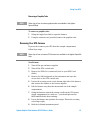
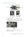
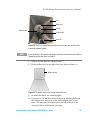
1
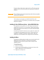
Agilent Graphite Tube Atomizer GTA 120 (Including GTA Viewing and Fume Extraction Apparatus) User’s Guide Notices © Agilent Technologies, Inc. 1993, 1995-1997, 2003, 2004, 2010 and 2012 No part of this manual may be reproduced in any form or by any means (including electronic storage and retrieval or translation into a foreign language) without prior agreement and written consent from Agilent Technologies, Inc. as governed by United States and international copyright laws. Manual Part Number 8510118500 Edition Eighth edition, April 2012 Agilent Technologies, Inc. Errata Statement NOTICE: This document contains references to Varian. Please note that Varian, Inc. is now part of Agilent Technologies. For more information, go to www.agilent.com. Warranty The material contained in this document is provided “as is,” and is subject to being changed, without notice, in future editions. Further, to the maximum extent permitted by applicable law, Agilent disclaims all warranties, either express or implied, with regard to this manual and any information contained herein, including but not limited to the implied warranties of merchantability and fitness for a particular purpose. Agilent shall not be liable for errors or for incidental or consequential damages in connection with the furnishing, use, or performance of this document or of any information contained herein. Should Agilent and the user have a separate written agreement with warranty terms covering the material in this document that conflict with these terms, the warranty terms in the separate agreement shall control. Technology Licenses The hardware and/or software described in this document are furnished under a license and may be used or copied only in accordance with the terms of such license. Restricted Rights Legend If software is for use in the performance of a U.S. Government prime contract or subcontract, Software is delivered and licensed as “Commercial computer software” as defined in DFAR 252.227-7014 (June 1995), or as a “commercial item” as defined in FAR 2.101(a) or as “Restricted computer software” as defined in FAR 52.227-19 (June 1987) or any equivalent agency regulation or 2 contract clause. Use, duplication or disclosure of Software is subject to Agilent Technologies’ standard commercial license terms, and nonDOD Departments and Agencies of the U.S. Government will receive no greater than Restricted Rights as defined in FAR 52.227-19(c)(1-2) (June 1987). U.S. Government users will receive no greater than Limited Rights as defined in FAR 52.227-14 (June 1987) or DFAR 252.227-7015 (b)(2) (November 1995), as applicable in any technical data. Safety Notices CAUTION A CAUTION notice denotes a hazard. It calls attention to an operating procedure, practice, or the like that, if not correctly performed or adhered to, could result in damage to the product or loss of important data. Do not proceed beyond a CAUTION notice until the indicated conditions are fully understood and met. WARNING A WARNING notice denotes a hazard. It calls attention to an operating procedure, practice, or the like that, if not correctly performed or adhered to, could result in personal injury or death. Do not proceed beyond a WARNING notice until the indicated conditions are fully understood and met. Agilent Graphite Tube Atomizer GTA 120 User’s Guide Contents Contents 1. Safety Practices and Hazards 7 General 7 Warning and Caution Messages 9 Warning Symbols 10 Notes 11 Color Coding 11 Electrical Hazards 12 Compressed Gas Hazards 13 Chemical Hazards 14 Other 14 Electromagnetic Compatibility 15 EN55011/CISPR11 ICES/NMB-001 2. Introduction 15 16 17 Working Environment 18 Specifications 18 Environmental Conditions Power Gas Supplies Water Supply Weights and Dimensions Agilent Graphite Tube Atomizer GTA 120 User’s Guide 18 18 20 21 21 3 Contents 3. Getting Started 23 GTA Control Unit 24 Front View Back View GTA Furnace 26 Water Supplies 26 Gas Supplies 27 4. Using Your GTA 29 Installation 30 Moving the Accessory 30 Installing the Control Unit 30 Installing the Furnace 31 Non-Zeeman GTA Zeeman GTA 31 32 Setting the Gas Supply 34 Turning on the Water Supply 34 Installing the Tube-CAM Camera Option – Agilent 240/280 AA Only 35 Installing the Mirror 35 The Optional GTA Viewing/Fume Extraction Accessory 36 Installing the Programmable Sample Dispenser (PSD) 36 Graphite Tubes and Platforms 36 Types of Available Graphite Tubes Types of Available Graphite Platforms 4 24 25 37 37 Agilent Graphite Tube Atomizer GTA 120 User’s Guide Contents Inserting a Graphite Tube Removing a Graphite Tube Removing Your GTA Furnace 5. The GTA Viewing/Fume Extraction Accessory (Optional) 39 41 41 43 Requirements for Fume Extraction 44 Installing the GTA Viewing/Fume Extraction Accessory 45 Installing the GTA Viewing/Fume Extraction Accessory to the Instrument Installing the Extraction System to the Laboratory Exhaust System Operation and Maintenance 6. Maintenance 45 48 51 53 General 53 Graphite Shroud and Electrodes 54 Hoses and Connections 54 Cleaning the Quartz Windows 54 Removing and Replacing Electrodes 55 Non-Zeeman Electrode Removal Non-Zeeman Electrode Replacement Zeeman Electrode Removal Zeeman Electrode Replacement Fuses Agilent Graphite Tube Atomizer GTA 120 User’s Guide 56 58 60 63 64 5 Contents This page is intentionally left blank. 6 Agilent Graphite Tube Atomizer GTA 120 User’s Guide Safety Practices and Hazards 1. Safety Practices and Hazards General Warning and Caution Messages Warning Symbols Notes Color Coding Electrical Hazards Compressed Gas Hazards Chemical Hazards Other Electromagnetic Compatibility 7 9 10 11 11 12 13 14 14 15 General A Graphite Tube Atomizer, used in conjunction with an Atomic Absorption spectrometer, uses compressed inert gases and high voltages. The system generates radiant energy and hazardous wastes including corrosive fluids and flammable liquids. Careless, improper or unskilled use of this system can cause death or serious injury to personnel, or severe damage to equipment and property. All users of an AA (Atomic Absorption) and GTA (Graphite Tube Atomizer) instrument must be familiar with the correct operating procedures. Appropriate safety practices have been included in this operation manual and your spectrometer operation manual, to help you operate the equipment safely. Read all safety practices thoroughly before attempting to operate your system. Agilent Graphite Tube Atomizer GTA 120 User’s Guide 7 Safety Practices and Hazards The covers on instruments and accessories must not be removed by the operator, except as permitted for the routine maintenance tasks detailed in the relevant operation manuals. Service is to be performed only by Agilent field support engineers. The safety practices described below are provided to help you operate your instrument safely. Read these safety practices thoroughly before attempting to operate the instrument and always operate the spectrometer in accordance with these safety practices. The GTA uses interlocks and covers which are designed to prevent accidental contact with any of the potential hazards. It is good practice, however, to develop safe working habits which do not depend upon the correct operation of the interlocks for safe operation. It is essential that no interlock or cover is bypassed, damaged or removed. Fumes generated by the GTA can be hazardous, and must be extracted by an exhaust system. Ensure that an exhaust of the appropriate type is fitted, as specified in the pre-installation instructions. It must be vented to the outside air, never within the building. Regularly check the exhaust system by smoke test to ensure that it is functioning correctly. Always switch the exhaust fan on before operating the instrument. WARNING 8 Noxious Gas An exhaust system must be used with an Agilent AA flame and furnace instruments to remove hazardous and toxic gases. Agilent Graphite Tube Atomizer GTA 120 User’s Guide Safety Practices and Hazards Warning and Caution Messages A Warning message is used in the text when failure to observe instructions or precautions could result in death or injury. The list of symbols that appear in conjunction with warnings are detailed in the next section. WARNING Name of Warning Detail of hazard. A Caution message is used when failure to observe instructions could result in damage to equipment (Agilent supplied and/or other associated equipment). CAUTION This is a caution statement. Agilent Graphite Tube Atomizer GTA 120 User’s Guide 9 Safety Practices and Hazards Warning Symbols The following is a list of symbols that appear in this manual in conjunction with warnings on the instrument. The hazard they describe is also shown. A triangular symbol indicates a warning. The meanings of the symbols that may appear alongside warnings in the documentation or on the instrument itself are as follows: Corrosive liquid Electrical shock Explosion hazard Eye hazard Fire hazard Heavy weight (danger to feet) Heavy weight (danger to hands) Hot surface Magnetic hazard Moving parts Noxious gas Toxic hazard The following symbol may be used on warning labels attached to the instrument or in this manual. When you see this symbol, refer to the relevant operation or service manual for the correct procedure referred to by that warning label. 10 Agilent Graphite Tube Atomizer GTA 120 User’s Guide Safety Practices and Hazards The following symbols appear on the instrument for your information. I Mains power on 0 Mains power off Fuse Single phase alternating current When attached to the rear of the instrument, indicates that the product complies with the requirements of one or more EU directives. When attached to the rear of the product, indicates that the product has been certified (evaluated) to CSA 61010.1 and UL 61010-1 Notes A Note is used to give advice or information. The format of a Note is as follows: NOTE Note text appears here. Color Coding The various indicator lights appearing on the accessory has been color coded to represent the status of the accessory: A green light indicates the instrument is in normal/standby condition. An orange light indicates that a potential hazard is present. A blue light indicates that operator intervention is required. A red light warns of danger or an emergency. Agilent Graphite Tube Atomizer GTA 120 User’s Guide 11 Safety Practices and Hazards Electrical Hazards The GTA electronic control module contains electrical circuits, devices and components operating at dangerous voltages. Contact with these circuits, devices and components can cause death, serious injury or painful electric shock. Panels or covers that are retained by screws on the GTA may only be opened by Agilent field service engineers. Use of the wrong supply voltage, connection of the accessory to an incorrectly wired supply outlet, or lack of proper electrical grounding can create a fire or shock hazard that can cause death, serious injury, or serious damage to equipment. 1 Always use a 3-wire outlet with a ground connection that is adequately rated for the load. 2 The installation must comply with local, state and national safety regulations. 3 Before connecting the GTA, make sure the voltage selector is correctly set for the mains supply to which you are going to connect the accessory. If not you should contact an Agilent field service engineer. A blown fuse should be replaced with one of the size and rating stipulated in the text adjacent to the fuse holder. Always ensure the accessory is turned off and disconnected from the mains supply before attempting any replacement. WARNING 12 Electrical Shock Never attempt to override or disable interlocks. Failure to observe this warning can result in death or serious injury. You must always disconnect the mains power inputs when direct access to the electronics is needed. Agilent Graphite Tube Atomizer GTA 120 User’s Guide Safety Practices and Hazards WARNING Magnetic Hazard The Zeeman magnet generates a variable magnetic field of 0.8 Tesla (at mains frequency) in the workhead. Pacemakers and magnetic storage media must be kept at least 300 mm from the magnet. Compressed Gas Hazards All compressed gases other than air can create a hazard if they leak into the atmosphere. Even small leaks in gas supply systems can be dangerous. Any leak other than air can result in an oxygen-deficient atmosphere which can cause asphyxiation or anesthesia. Gas cylinders must be stored and handled strictly in accordance with local safety codes and regulations. Cylinders must be used and stored only in a vertical position and secured to an immovable structure or a properly constructed cylinder stand. Move cylinders only on a properly constructed trolley. The area in which cylinders are stored and the area surrounding the instrument must be adequately ventilated to prevent accumulations of gas. Use only approved regulator and hose connectors; refer to the gas supplier’s instructions. Keep gas cylinders cool and properly labeled, all cylinders are fitted with a pressure relief device which will rupture and empty the cylinder if the internal pressure rises above the safe limit. Use only ‘Instrument Grade’ gases with the spectrometer. Ensure that you have the right cylinder before connecting it to the instrument. Always ensure that the gas supplies are turned off at the cylinders or tanks after completing an analytical procedure and at the end of the working day. Shut off valves should be installed and easily accessible. Agilent Graphite Tube Atomizer GTA 120 User’s Guide 13 Safety Practices and Hazards Chemical Hazards The GTA accessory may involve the use of materials which are toxic, highly corrosive or otherwise hazardous. Careless, improper, or unskilled use of such materials can cause serious personal injury. Always ensure that laboratory safety practices governing the use, handling and disposal of such materials are strictly observed. These safety practices should include the wearing of appropriate safety clothing. Before attempting any work on the sample compartment area, you must know exactly what matrix of solutions has been running through the instrument and particularly what types of solvents are involved. Always check that the Programmable Sample Dispenser (PSD) has been thoroughly flushed out with distilled water and that the contents of the drain or waste container are known and properly disposed of if necessary before touching any part. Wash your hands and gloves thoroughly during the course of sample compartment work. Avoid contact between hands and eyes at all times during servicing of the instrument. Other GTA control units are heavy. To avoid injury, or damage to the control unit, two people are needed to move the instrument to the bench location. Cooling air flow to the spectrometer and the GTA must be unobstructed. Do not block the ventilation grills. Do not position the equipment so that it is difficult to operate the disconnecting device. 14 Agilent Graphite Tube Atomizer GTA 120 User’s Guide Safety Practices and Hazards Electromagnetic Compatibility EN55011/CISPR11 Group 1 ISM equipment: group 1 contains all ISM equipment in which there is intentionally generated and/or used conductively coupled radio- frequency energy which is necessary for the internal functioning of the equipment itself. Class A equipment is equipment suitable for use in all establishments other than domestic and those directly connected to a low voltage power supply network which supplies buildings used for domestic purposes. This device complies with the requirements of CISPR11, Group 1, Class A as radiation professional equipment. Therefore, there may be potential difficulties in ensuring electromagnetic compatibility in other environments, due to conducted as well as radiated disturbances. Operation is subject to the following two conditions: 1 This device may not cause harmful interference. 2 This device must accept any interference received, including interference that may cause undesired operation. Agilent Graphite Tube Atomizer GTA 120 User’s Guide 15 Safety Practices and Hazards If this equipment does cause harmful interference to radio or television reception, which can be determined by turning the equipment off and on, the user is encouraged to try one or more of the following measures: 1 Relocate the radio or antenna. 2 Move the device away from the radio or television. 3 Plug the device into a different electrical outlet, so that the device and the radio or television are on separate electrical circuits. 4 Make sure that all peripheral devices are also certified. 5 Make sure that appropriate cables are used to connect the device to peripheral equipment. 6 Consult your equipment dealer, Agilent Technologies, or an experienced technician for assistance. 7 Changes or modifications not expressly approved by Agilent Technologies could void the user’s authority to operate the equipment. ICES/NMB-001 This ISM device complies with Canadian ICES- 001. Cet appareil ISM est conforme à la norme NMB-001 du Canada. 16 Agilent Graphite Tube Atomizer GTA 120 User’s Guide Introduction 2. Introduction Working Environment Specifications Environmental Conditions Power Gas Supplies Water Supply Weights and Dimensions 18 18 18 18 20 21 21 This manual describes how to install and operate a Graphite Tube Atomizer (GTA) and Zeeman GTA with Agilent AA spectrometers. Your GTA consists of a control unit and a furnace. This manual describes how to install and disconnect the control unit, along with how to install, remove and maintain the furnace for optimum performance. NOTE The GTA 120 is compatible with the Agilent 200 Series AA (including the 140 AA) ONLY. More information on the operation of your GTA can be found in the comprehensive reference supplied with your GTA — ‘Analytical Methods for Graphite Tube Atomizers'. Agilent Graphite Tube Atomizer GTA 120 User’s Guide 17 Introduction Working Environment Graphite tube atomization is a microanalytical technique which demands a particularly high standard of care in all activities to ensure good precision and accuracy of the analytical result. Strict cleanliness is essential in all laboratory procedures — contamination must be avoided. Ideally, your laboratory should be air-conditioned and draught-free. All sample preparation should be carried out in an area which is well separated from the instrument. Specifications Environmental Conditions Your accessory is designed for indoor use only. It is suitable for the following categories: Installation category II Pollution degree 2 Equipment class I Condition Altitude Temp (°C) Humidity (%RH) non-condensing Non-operating (storage) 0-2133 m (0-7000') 5-45 20-80 Operating within performance specifications 0-853 m (0-2800') 853-2133 m (2800-7000') 10-35 8-80 10-25 8-80 Power Voltage 208, 220, or 240 volts AC ± 10%, 230 +14% -6% volts AC, 230 +6% -14% volts AC. Frequency 50-60 Hz ±1 Hz Normal standby consumption approx 130 VA Rated firing consumption approx 3500 VA 18 Agilent Graphite Tube Atomizer GTA 120 User’s Guide Introduction NOTE The GTA will draw surge currents in excess of the nominal rating of 15 A (3500 VA). Surges in the GTA accessory depend on the choice of ramp rate and programmed temperature and may be up to 40 A for approximately 1 second, reducing to about 20 A for up to 10 seconds, perhaps repeating every 1 to 2 minutes. Electrical Connections Mains power cord connector: NOTE Australia: Clipsal 439D15M USA: Complies with NEMA L6-30P (Hubbel#2621) Europe: Kaiser CEBEC 616 VDE (complies with DIN 49441R2) The GTA 120 has a captive cable. 25 pin D-range type (for Programmable Sample Dispenser) is located in the instrument power supply compartment. NOTE To access this 25 pin connector you must open the GTA power supply door . IEEE-488 is at the rear of the instrument. Zeeman furnace: CPC 14-way connection into the left hand side panel of a Zeeman spectrometer (behind the exterior panel). Fuses FS3, FS5: T1.6 AL 250 V, IEC60127-2 Sheet 3, 5x20 mm, Littelfuse 0218016 or equivalent FS4: T2.5 AL 250 V, UL/CSA/ANCE 248, 5x20 mm, Littelfuse 0239025 or equivalent FS1, FS2: T1.6 AH 250 V, IEC60127-2 Sheet 5, 5x20 mm, Littelfuse 0215016 or equivalent Agilent Graphite Tube Atomizer GTA 120 User’s Guide 19 Introduction NOTE For safety reasons, any other internal fuse or circuit breaker is not operator accessible, and should be replaced only by Agilent authorized personnel. Fuse information on the rear of the instrument is the most up to date. Gas Supplies An inert gas is always needed at the ‘Normal’ gas inlet to the GTA. This gas is used to shroud the hot graphite components and prevent oxidation. The preferred gas for the ‘Normal’ gas inlet is argon. Nitrogen is an acceptable lower cost alternative but furnace performance may be degraded for some elements and tube lifetime may be reduced. The argon or nitrogen used must be at least 99.99% pure. Nitrogen or air may be used at the ‘Alternate’ gas inlet. A choice is made on the basis of the analytical technique for the sample. NOTE Recommendations are made in the document ‘Analytical Methods for Graphite Tube Atomizers’. Gas supplies must be regulated to maintain the instrument operating pressure under dynamic conditions. The gas must be dry and dust-free; otherwise you must insert a suitable filter in the supply line. Recommended pressure: 140 kPa (20 psi) Maximum pressure: 350 kPa (50 psi) Normal flow rate approx 0–3.5 L/min Normal gas connection is 6 mm (1/4 in.) barb. Alternate gas connection is 6 mm (1/4 in.) barb. Snap-on gas connector for PSD accessory inside power supply panel. 20 Agilent Graphite Tube Atomizer GTA 120 User’s Guide Introduction Water Supply NOTE Maximum temperature 40 °C (104 °F) Recommended temp. range 18–25 °C (64–70 °F) Water temperature should be set above the dew point to avoid condensation forming on the workhead surfaces. Minimum flow rate required 1.5 L/min at 180 kPa (27 psi) Typical flow rate at recommended pressure range 1.5–2.0 L/min Maximum pressure to the regulator 700 kPa (100 psi) Typically removes 950 W of heat at 20 °C. Water connections are 6 mm (1/4 in.) barb, inlet and outlet. Weights and Dimensions Weight Net 41 kg (91 lb) Shipping 76 kg (168 lb) Dimensions (W x D x H) Control unit 240 x 570 x 580 mm (10 x 22 x 23 in) Furnace 150 x 150 x 340 mm (6 x 6 x 13 in) Packed 950 x 760 x 900 mm (37 x 30 x 35 in) [includes PSD] GTA 120 Zeeman Weight Net 52 kg (113 lb) Shipping 87 kg (192 lb) Dimensions (W x D x H) Control unit 240 x 570 x 580 mm (10 x 22 x 23 in) Zeeman 220 x 290 x 340 mm (9 x 11 x 13 in) Packed 950 x 760 x 900 mm (37 x 30 x 35 in) [includes PSD] The length of the connection between the control unit and the furnace (the umbilical cord) is 380 mm (15 in.). Agilent Graphite Tube Atomizer GTA 120 User’s Guide 21 Introduction This page is intentionally left blank. 22 Agilent Graphite Tube Atomizer GTA 120 User’s Guide Getting Started 3. Getting Started GTA Control Unit Front View Back View GTA Furnace Water Supplies Gas Supplies 24 24 25 26 26 27 Your GTA consists of a control unit and a furnace, permanently connected to each other by a flexible umbilical tube. This tube contains the water and gas supplies as well as the power and control cable for your GTA furnace. For Zeeman instruments, the furnace is also connected to the instrument by a cable that plugs into the main instrument. For non-Zeeman spectrometers, the GTA furnace is installed in the sample compartment of your instrument when operating in furnace mode. When operating in flame mode, you must remove the furnace from the sample compartment and place it in the storage location inside the control unit. For Zeeman spectrometers, the furnace can remain in the sample compartment at all times. The GTA uses the PSD (Programmable Sample Dispenser) to automatically deliver measured volumes of sample to the furnace. Agilent Graphite Tube Atomizer GTA 120 User’s Guide 23 Getting Started GTA Control Unit The GTA control unit controls the furnace by regulating the temperature and controlling the gas supply in accordance with the parameters set in the current software method. Similarly, the unit also controls the Programmable Sample Dispenser (PSD). Front View On the front panel of your GTA control unit are the power switch and the ‘power on’ indicator. The inert gas supply for the Programmable Sample Dispenser (PSD) and the PSD control socket are located in the power supply compartment. (The power supply compartment door must be opened to access these). Figure 1. The ‘power on’ indicator and power switch (right, bottom center of the photo) and the power supply compartment door being opened (left). Power Switch and Indicator The power switch and indicator are on the front of the control unit. The indicator lights up when the GTA is on. The power switch is a rocker type on-off circuit breaker for the mains power supply, which also provides over-current protection. NOTE 24 If the atomizer is held at high temperatures (2800 °C) for long periods of time (20 seconds) the circuit breaker may trip. Agilent Graphite Tube Atomizer GTA 120 User’s Guide Getting Started If the circuit breaker trips open during normal operation, this indicates an over-current fault condition. Wait for at least 20 seconds before attempting to close the circuit breaker again. If the circuit breaker will not remain closed, call your Agilent field service engineer. Programmable Sample Dispenser Connections The Programmable Sample Dispenser (PSD) is used with the GTA to dispense solutions into the furnace. The inert gas supply connector and control plug connector for the PSD are located in the power supply compartment. See Figure 1 above. The gas supply connector is a quick-connect automatic seal-off type connector. This provides inert gas to pressurize the sampler rinse system. The control connector is a 25-way ‘D’ connector, which provides drive and control signals for the PSD and power for the dispenser actuator system. For more details about the PSD and its installation refer to the PSD User’s Guide. Back View The back of the GTA control unit contains the appropriate inlets for the power, water and gas supplies. A communications cable connects the GTA to the computer IEEE card via the spectrometer. The GTA will be set up, ready for use by a field service engineer during installation. However, you can also refer to sections on the Pages 26 and 27 for more information on the water and gas supplies. Agilent Graphite Tube Atomizer GTA 120 User’s Guide 25 Getting Started Figure 2. Back of the GTA 120 control unit GTA Furnace The GTA furnace consists of an electrically heated graphite tube located in a chamber with windows at each end. A toggle lever at the front left allows you to open one end of the furnace to insert or remove graphite tubes. Water Supplies During installation of your GTA, the Agilent field service engineer will connect the water supply. The water pressure is set in accordance with the specifications listed in Section 2. A continuous supply of cooling water must be provided for the GTA furnace. If there is insufficient water (for example, not enough pressure, failure of the supply, the supply is turned off), an interlock will prevent the atomizer system from operating. A fault message will be displayed on the screen and a beeper will sound. The water supply must be restored before the GTA can be restarted. An automatic cutout will stop operation if the water temperature exceeds the maximum temperature as specified in the ‘Water Supply’ section on Page 21. NOTE 26 Ensure that the return path is not blocked or switched off. Agilent Graphite Tube Atomizer GTA 120 User’s Guide Getting Started Gas Supplies Two gas inlets are provided, ‘Normal' and ‘Alternate'. The supply of gas to the GTA is set up and regulated during installation by an Agilent field service engineer. NOTE Depending on your requirements at the time, the alternate gas supply may not have been connected at installation. If you need to add this supply later, connect a gas supply to the alternate gas inlet, regulated as per the specifications provided in Section 2. The gas pressure is set at installation in accordance with the specifications included in Section 2. You should be aware of the following points: Inert gas must be supplied through the ‘Normal’ inlet at the back of the control unit; otherwise the system will not operate. If the gas supply is turned off or fails, a monitoring system will cause the system to stop. Both normal and alternate supplies are monitored. A supply failure in a gas needed by your method will cause the system to stop, an error message to be displayed on the screen and the beeper to sound. As outlined in Section 2, the gas supplied through the ‘Normal’ inlet must be an inert gas (either nitrogen or argon) but you can use either an inert gas or other gases as the alternate gas. An alternate gas may be used for many reasons. For example, it can reduce background interferences. (This is seen in blood analyses, where air is the preferred gas for the ashing step as it removes more of the blood matrix components.) Refer to the SpectrAA Help or ‘Analytical Methods for Graphite Tube Atomizers' for more information on the use of alternate gases. Agilent Graphite Tube Atomizer GTA 120 User’s Guide 27 Getting Started TIP Although more expensive, argon will generally give better analytical sensitivity and longer tube life than nitrogen during the ‘Read’ stage. However it is possible to use nitrogen during the drying/ashing stages and argon during the ashing/atomization stage. This will reduce gas use costs. If you are not using an alternate gas, you should cover the inlet to protect against dust, moisture etc. If you use air, make sure that your furnace method is in accordance with the limitations on the use of air. NOTE If air ashing is employed, the flow should be high enough to remove ashing products and generally assist the ashing process. Do not use air at graphite tube temperatures above 250 °C, as this will cause excessive deterioration of the graphite furnace tube. All gases must be clean, dry and of high purity. WARNING 28 Fire and Explosion Hazard To avoid a fire or explosion which could result in death or serious personal injury, burns or property damage, NEVER use pure hydrogen (or any gas with a hydrogen content greater than 5%) in the GTA. You may use a proprietary, pre-packaged mixture of 95% argon and 5% hydrogen as an alternate gas. Agilent Graphite Tube Atomizer GTA 120 User’s Guide Using Your GTA 4. Using Your GTA Installation Moving the Accessory Installing the Control Unit Installing the Furnace Non-Zeeman GTA Zeeman GTA Setting the Gas Supply Turning on the Water Supply Installing the Tube-CAM Camera Option – Agilent 240/280 AA Only Installing the Mirror The Optional GTA Viewing/Fume Extraction Accessory Installing the Programmable Sample Dispenser (PSD) Graphite Tubes and Platforms Types of Available Graphite Tubes Types of Available Graphite Platforms Inserting a Graphite Tube Removing a Graphite Tube Removing Your GTA Furnace Agilent Graphite Tube Atomizer GTA 120 User’s Guide 30 30 30 31 31 32 34 34 35 35 36 36 36 37 37 39 41 41 29 Using Your GTA Installation Before proceeding, you should have: Read the Safety section in this manual and your instrument User’s Guide Set up the AA instrument Moving the Accessory WARNING Heavy Weight – Danger to Hands and Feet When packed, the GTA weighs up to 87 kg (192 lb). To avoid injury to personnel, or accidental damage to equipment, do not attempt to lift the package alone. Installing the Control Unit The control unit should have already been set up by an Agilent Field Service Representative. If you wish to move the GTA you will need to disconnect the control unit's mains power cable, gas hose(s) and water hoses from their respective supplies. To install the control unit you must: 30 Plug the mains power cable into the mains power supply. Connect the gas and water supplies as described in the previous chapter. Agilent Graphite Tube Atomizer GTA 120 User’s Guide Using Your GTA Installing the Furnace Non-Zeeman GTA Before installation, the GTA 120 furnace will be kept in the storage location on the control unit. To remove the GTA 120 furnace from its storage cradle and install it in the sample compartment: 1 Ensure that both the spectrometer and GTA control unit are switched off and that the spraychamber, etc. have been removed and safely stowed. 2 Remove the instrument left panel, and remove the cut-out fill plate, if applicable. To do this, lift the bottom of the panel upward and then pull it forward (see Figure 4). 3 Undo the retaining screw (see Figure 3), then remove the GTA workhead from its storage position in the power supply compartment. Retaining screw Figure 3. Location of the retaining screw Agilent Graphite Tube Atomizer GTA 120 User’s Guide 31 Using Your GTA NOTE NOTE 4 Look under the furnace and note the position of two spigots (near the toggle lever). These will fit into the two holes on the top of the burner adjuster on the left side of the sample compartment. Similarly, note the presence of one stainless steel spigot near the base of the furnace. When you install the furnace, this will be inserted into a slot in the burner adjuster. 5 Tilt the furnace slightly to the left and engage the two spigots in the top of the burner adjuster. Then insert the metal spigot into the slot. 6 Tighten the securing screw on the bottom right-hand side of the furnace so that the furnace is firmly secured to the mounting block. The umbilical should be recessed behind the front panel of the instrument. (The front panel has a cutout in it to accommodate this.) 7 Align the furnace. Refer to the SpectrAA Help for details on how to do this. 8 Replace the instrument left panel. For instruction about how to install and adjust the Programmable Sample Dispenser (PSD) refer to the PSD User’s Guide. Zeeman GTA The furnace will have been installed by an Agilent field service engineer during installation of the instrument. However, if you have removed the furnace to replace the electrodes or clean the sample compartment, reinstall the furnace workhead as follows: 32 1 Ensure that both the spectrometer and GTA control unit are switched off. 2 Remove the left panel on the instrument. To do this, lift the bottom of the panel upward and then pull it forward (see Figure 4). Agilent Graphite Tube Atomizer GTA 120 User’s Guide Using Your GTA Figure 4. Removing the left panel on the instrument 3 Lift the furnace towards the sample compartment, ensuring the umbilical cord is not twisted as you do so. 4 Keeping the power cord out of the way, lower the workhead onto the rollers, with the slots over the rollers. 5 Ensuring the furnace is correctly installed; carefully pull the top of the workhead towards you. It should tilt about 30° then rest on the stops. 6 Plug the furnace power cable plug into the socket located on the rear wall of the compartment exposed when the left panel was removed (see Figure 5). Figure 5. Power cable plugged into connector on the 280Z AA Agilent Graphite Tube Atomizer GTA 120 User’s Guide 33 Using Your GTA NOTE Rotate the plug to match the pins in the socket and then push the plug in. Screw the collar up finger tight until it locks into position. CAUTION Ensure the plug is securely in place. A loose plug will lead to arcing between the pins of the plug and damage to the electrical system of the instrument. 7 Refit the left hand panel. 8 Align the HC lamps. Refer to the SpectrAA Help for instructions. 9 Carefully tilt the workhead back into the sample compartment. 10 Align the vertical furnace position. Setting the Gas Supply Turn on the gas supplies at the cylinders and set the regulators as detailed in the ‘Specifications’ section on Page 18. CAUTION The use of pressures above the recommended maximum may burst internal gas hoses, requiring service replacement. Turning on the Water Supply If you are using a recirculating system, you should refer to its operating instructions. NOTE 34 Refer to the required water pressures listed in the ‘Water Supply’ section on Page 21. Agilent Graphite Tube Atomizer GTA 120 User’s Guide Using Your GTA If you are using a mains water supply, turn it on. The water pressure regulator was set at the factory as per the specifications included in Section 2. CAUTION The use of higher pressures may burst water hoses within the furnace assembly, requiring service replacement. After turning on your supply, you should check all hoses and connections for leaks. If you find any you should contact your Agilent field service engineer. Installing the Tube-CAM Camera Option – Agilent 240/280 AA Only This optional accessory allows you to view images from inside the graphite tube on your PC so you can monitor sample drying during method development and accurately set the probe dispensing height during alignment. If you have purchased the camera accessory option, the camera will be installed in your instrument at the factory. Camera drivers are supplied on a CD-ROM. To install the camera drivers, follow the instructions on the Installation sheet shipped with the instrument. Installing the Mirror You may have ordered a mirror to allow you to view the inside of the graphite tube in the GTA furnace. This may help in method development (observing the dry phase) and in setting the PSD capillary position. To install this mirror: 1 Remove the chimney. 2 Clip the mirror mounting block over the bar at the front of the sample compartment, on the left hand side. 3 Tighten the securing screw. Agilent Graphite Tube Atomizer GTA 120 User’s Guide 35 Using Your GTA The mirror can be rotated and moved up or down the shaft. When you want to use the mirror, swing the mirror lever so that the mirror is in front of the atomizer window, and adjust the height and angle of the mirror so that you can view the inside of the graphite tube atomizer. WARNING Eye Hazard To avoid eye damage DO NOT look at a glowing furnace. The Optional GTA Viewing/Fume Extraction Accessory If you are using the GTA viewing/fume extraction accessory, you should install it now. Refer to Section 5 for installation instructions. Installing the Programmable Sample Dispenser (PSD) To install the PSD, follow the instructions in your PSD User’s Guide. Graphite Tubes and Platforms After setting up your GTA (and PSD), you can insert a graphite tube and start your analytical run according to your instrument operation manual. This section describes the types of tubes and platforms available and how to install and remove them. 36 Agilent Graphite Tube Atomizer GTA 120 User’s Guide Using Your GTA WARNING Hot Surface Parts of the furnace become very hot during use. To prevent burns, ALWAYS allow the furnace to cool before touching. Types of Available Graphite Tubes Description Part number Omega platform tube, pyrolytically coated (Packet of 10) 6310003700 Partitioned tube, pyrolytically coated (Packet of 10) 6310001200 Plateau, pyrolytically coated (Packet of 10) required for use with pyrolytic graphite platforms 6310001100 Picture Types of Available Graphite Platforms Description Part number Platforms, solid pyrolytic graphite (Packet of 10) for use with plateau tubes only 6310001300 Picture ‘Forked’ Platforms These platforms are inserted into grooves in a notched partitioned tube. The instructions for inserting a forked platform into the furnace are contained in its instruction booklet. Agilent Graphite Tube Atomizer GTA 120 User’s Guide 37 Using Your GTA Normal Platforms For normal platforms in plateau tubes, first insert the platform so that it is horizontal to, and centered around the injection hole. Then place the tube into the graphite shroud following Steps 3 and 4 in the ‘Inserting a Graphite Tube’ section starting on Page 39. You will now need to re-check that the platform is still horizontal to the injection hole. Because the mirror is angled when used to view the graphite tube, you must use a capillary or pipette tip to determine if the platform is horizontal. Insert the pipette tip and, with the mirror, check that the platform is perpendicular to the tip. NOTE If you are using the Tube-CAM to align the platform, you will still need to check the vertical alignment since the camera may not be completely level. Alternatively, you can attach and start the sample dispenser and check that the sampler dispensing capillary is perpendicular to the platform. Refer to your PSD operation manual. NOTE Normal platforms cannot be used with partitioned tubes. Figure 6. Correct positioning of a graphite platform inside a plateau tube Figure 7. Correct positioning of a forked platform inside a notched tube 38 Agilent Graphite Tube Atomizer GTA 120 User’s Guide Using Your GTA Inserting a Graphite Tube To insert a graphite tube: 1 NOTE If you are using a Zeeman graphite furnace, tilt the furnace assembly forward to access the top of the furnace. Some operators may find it easier to tilt the furnace when inserting a graphite tube. However it is possible to carry out this procedure without tilting the furnace. If you are going to tilt the furnace, the PSD must first be removed. 2 Open the furnace and insert the graphite tube into the furnace taking care to ensure the injection hole is on top. NOTE Handle graphite tubes with care and only in a clean working environment. NOTE Video clips of how to insert graphite tubes are available in the Agilent SpectrAA Help. 3 Place the alignment tool through the hole at the top of the furnace and into the hole in the graphite tube. 4 Close the workhead using the accessory lever. This will hold the graphite tube in the correct position. Agilent Graphite Tube Atomizer GTA 120 User’s Guide 39 Using Your GTA Figure 8. Aligning the graphite tube using the alignment tool 5 Push the furnace back into position. ✓ ✗ Figure 9. Using the tool ensures correct injection hole positioning (top view). NOTE 40 BEFORE using a new graphite tube for analyses, condition the tube by using the condition tube function, accessible from furnace facilities. This will run the current furnace temperature program injecting blank and any modifier solution (if programmed). Conditioning the tube removes any residual contamination from the tube. (The tube clean facility should only be used on already conditioned tubes.) Agilent Graphite Tube Atomizer GTA 120 User’s Guide Using Your GTA Removing a Graphite Tube NOTE Video clips of how to remove graphite tubes are available in the Agilent SpectrAA Help. To remove a graphite tube: 1 Swing the toggle lever fully to open the furnace. 2 Using the extractor tool provided, remove the graphite tube. Removing Your GTA Furnace If you need to remove your GTA from the sample compartment, follow these steps: NOTE Video clips of how to remove GTA furnaces are available in the Agilent SpectrAA Help. Non-Zeeman: 1 Turn off the gas and water supplies. 2 Turn off the GTA control unit. 3 Remove the PSD if it is connected (refer to your PSD User’s Guide). 4 Remove the left hand panel on the instrument and open the access door on the GTA control unit. 5 Loosen the securing screw on the bottom right side of the furnace that secures the furnace to the burner adjuster. 6 Lift the furnace away from the mount and out of the sample compartment. 7 Swing the furnace toward the storage cradle on the GTA power supply compartment in a wide arc — you should prevent the black umbilical tube from twisting. 8 Lower the furnace into position for storage. Fasten the securing screw finger tight. 9 Refit the left hand instrument panel. Agilent Graphite Tube Atomizer GTA 120 User’s Guide 41 Using Your GTA Zeeman WARNING 42 1 Turn off the gas and water supplies. 2 Turn off the spectrometer and the GTA control unit. 3 Remove the PSD if it is connected (refer to your PSD User’s Guide). 4 Tilt the furnace forward. 5 Remove the left hand panel on the instrument. 6 Unscrew the collar on the plug and remove the plug from the socket (280 AA Zeeman only). 7 Lift the furnace off the rollers and out of the sample compartment. 8 Place the furnace on a stable bench top. Heavy Weight – Danger to Hands and Feet The furnace workhead is very heavy. Use appropriate lifting techniques when moving the furnace. Particular care should be taken if the bench or trolley are positioned in front of the instrument. Agilent Graphite Tube Atomizer GTA 120 User’s Guide The GTA Viewing/Fume Extraction Accessory (Optional) 5. The GTA Viewing/Fume Extraction Accessory (Optional) Requirements for Fume Extraction Installing the GTA Viewing/Fume Extraction Accessory Installing the GTA Viewing/Fume Extraction Accessory to the Instrument Installing the Extraction System to the Laboratory Exhaust System Operation and Maintenance 44 45 45 48 51 The GTA viewing/fume extraction accessory is an optional addition to your Agilent AA instrument and can be used in conjunction with the mirror or the Tube-CAM to give you further control over the alignment of the graphite tube and PSD. NOTE The GTA viewing/fume extraction accessory is compatible with Agilent 280 AA, 240 AA and 140 AA instruments only. The GTA viewing/fume extraction accessory has three components: A mirror to allow you to view the workhead sample introduction port and simplify the alignment of the dispensing capillary. A light to illuminate the workhead for easier viewing of the graphite tube when aligning the PSD or when viewing using the optional Tube-CAM. An extraction port which can be connected to the instrument flue, enabling efficient removal of fumes and exhaust gases from the furnace during operation. Agilent Graphite Tube Atomizer GTA 120 User’s Guide 43 The GTA Viewing/Fume Extraction Accessory (Optional) The GTA viewing/fume extraction accessory can be used with graphite furnace operation on either a Flame or Zeeman instrument. NOTE It is easier to install the GTA viewing/fume extraction accessory when the PSD is not fitted. Requirements for Fume Extraction Recommended requirements for fume extraction: The GTA viewing/fume extraction accessory must be fitted to a suitable duct. The diameter of the duct must be either: 150 mm ± 2.5 mm (6 in.), or 125 mm ± 2.5 mm (5 in.). The extraction flow rate, without the GTA viewing/fume extraction accessory fitted, must be 6 m3/min (200 cfm), as specified in the Agilent AA Site Preparation Guide. For correct fume extraction, the flow rate through the GTA viewing/fume extraction accessory must be 0.27 m3/min (9.5 cfm). This gives a pressure drop across the device of approximately 0.1 kPa (0.014 psi), when measured between the inside of the extraction duct and the atmosphere, with the GTA viewing/fume extraction accessory fitted to the instrument. Refer to Figure 10. Performance is dependent on the configuration of the fume extraction system and fan characteristics. Contact your Agilent field service engineer if further assistance is required. To check the pressure, remove the handle and attach a suitable manometer. Figure 10. Checking the flow rate through the accessory 44 Agilent Graphite Tube Atomizer GTA 120 User’s Guide The GTA Viewing/Fume Extraction Accessory (Optional) NOTE You can check that fume extraction is occurring by installing the GTA viewing/fume extraction accessory, then running a sample that produces smoke and checking that all of the smoke is extracted from each firing. Whole blood is a suitable sample. Installing the GTA Viewing/Fume Extraction Accessory Installation of the GTA viewing/fume extraction accessory can be divided into two parts: fitting the accessory to the instrument, and connection of the accessory to the instrument flue. Exhaust hose Hose clip Handle Cover Adaptor plate D-type connector Mirror Figure 11. The components of the GTA viewing/fume extraction accessory Installing the GTA Viewing/Fume Extraction Accessory to the Instrument 1 Set the support bracket to the required location for your instrument type. To adjust the bracket, loosen the screws and slide the bracket to the desired position. Refer to Figures 12 and 13. Agilent Graphite Tube Atomizer GTA 120 User’s Guide 45 The GTA Viewing/Fume Extraction Accessory (Optional) Mounting bracket Support bracket Figure 12. The support bracket in the position for Zeeman instruments Figure 13. The support bracket in the position for D2 instruments 2 Set the mounting bracket to the highest position and gently tighten the screws. 3 Clip the accessory onto the flame shield. Make sure that the edge of the flame shield fits between the spring canoe-clips. Refer to Figures 14, 15 and 16. Edge of flame shield Figure 14. The GTA viewing/fume extraction accessory clips onto the flame shield and is secured by spring-clips. 46 Agilent Graphite Tube Atomizer GTA 120 User’s Guide The GTA Viewing/Fume Extraction Accessory (Optional) Figure 15. Note the correct location of the edge of the flame shield in relation to the spring clip on the accessory Figure 16. The canoe-clips hold the accessory in place firmly against the flame shield 4 The base of the accessory should sit 2–3 mm above the magnet/workhead. Loosen the mounting bracket screws and set the accessory to the correct height. Tighten the screw firmly. 5 Check that the accessory is firmly in place and cannot move from side to side. The curve at the bottom of the accessory should be centered over the sample port. Refer to Figure 17. Agilent Graphite Tube Atomizer GTA 120 User’s Guide 47 The GTA Viewing/Fume Extraction Accessory (Optional) Leave a 2–3 mm gap between the furnace and the rim of the accessory. Figure 17. The rim of the accessory should be centered over the sample port NOTE To adjust the position of the accessory, tilt the base forwards and lift it up slightly to enable the accessory to move freely. Move the accessory to the desired position and then press it down to lock into place. 6 Plug the accessory into the accessory port on the instrument using the 9 way D-type connector fitted to the accessory. The accessory port is located on the rear right hand side of the instrument. Installing the Extraction System to the Laboratory Exhaust System The GTA viewing/fume extraction accessory is connected to the extraction duct using an adaptor plate. Two plates are supplied with the accessory: use the longer one if you have a 150 mm (5 in.) duct and the smaller one if you have a 125 mm (5 in.) duct. If your duct is a different size, contact your local Agilent field service engineer. 48 Agilent Graphite Tube Atomizer GTA 120 User’s Guide The GTA Viewing/Fume Extraction Accessory (Optional) Flue Baffle rest Handle Adapter plate Exhaust hose Hose clip Figure 18. The GTA viewing/fume extraction accessory fits into the flue of the instrument exhaust system NOTE It may be easier to disconnect the exhaust hose from the accessory first. Refer to ‘Removing the Exhaust Hose’ on Page 51. 1 Remove the flue from the extraction duct. 2 Fit the baffle rest over the edge of the flue. Refer to Figure 19. Baffle rest step Figure 19. The baffle rest fits over the top edge of the flue 3 Re-attach the flue to the extraction duct. 4 If you have a 125 mm duct, unscrew the large adaptor plate from the exhaust hose and screw on the small adaptor plate. If you have a 150 mm duct, the adaptor plate already attached to the accessory will be sufficient for your duct. Agilent Graphite Tube Atomizer GTA 120 User’s Guide 49 The GTA Viewing/Fume Extraction Accessory (Optional) 5 Push the adaptor plate up into the flue at an angle of approximately 30 degrees. Continue to push the plate up until it is above the baffle rest. Refer to Figure 20. 6 Use the handle to pull the adapter plate down into position. The plate should rest on the baffle rest step. Elliptical plate Step on baffle Handle Exhaust hose Hose clip Figure 20. The adaptor plate fits onto the baffle rest at approximately a 30° angle NOTE CAUTION 50 The plate does not fit flat in the flue but should fit snugly, with no more than a 5 mm gap between the edge of the plate and the edge of the flue. 7 Adjust the position of the hose clip so that the lip is positioned on the edge of the flue. It is not necessary to physically attach the hose clip to the flue. When correctly adjusted, the hose clip will locate the exhaust hose to the rear of the flue. 8 If necessary, reconnect the exhaust hose to the accessory. The exhaust hose should be pushed down into the accessory until it is level with the white block at the bottom of the accessory (see Figure 21 on Page 52). 9 Once the GTA viewing/fume extraction accessory has been fitted to the instrument you can use it to view the workhead. Lift the cover on the accessory to illuminate the sample port and view down into the injection hole of the graphite tube, using the mirror built into the accessory. Before running the instrument in flame mode, remove the accessory from both the instrument and the exhaust duct. Agilent Graphite Tube Atomizer GTA 120 User’s Guide The GTA Viewing/Fume Extraction Accessory (Optional) Operation and Maintenance Cover Interlock The graphite furnace can NOT be started when the cover is open and the viewing mirror is exposed. However, once the furnace has started the cover can be lifted up to enable you to view the inside of the furnace. WARNING Hot Surface and Eye Hazard Do not place hands near the GTA viewing/fume extraction accessory during the atomization stage. You should NOT look into the accessory at this stage or into the mirror if the cover has been lifted up. Removing the Exhaust Hose Refer to Figure 21. To remove the hose, pull it down from the mounting (1) and then pull it out of the accessory (2). You may also want to cut the hose to a length suitable to the installation. When the hose is reinstalled it should sit approximately level with the base of the white block on the accessory. Refer to Figure 21. Agilent Graphite Tube Atomizer GTA 120 User’s Guide 51 The GTA Viewing/Fume Extraction Accessory (Optional) 2 1 Figure 21. The exhaust hose fits all the way into the accessory until it is level with the white block at the bottom. Note the directional arrows. NOTE To remove the exhaust hose from the adapter plate, simply unscrew it. Changing Location To adjust the position of the accessory, tilt the base forwards and lift it up slightly to enable the accessory to move freely. Move the accessory to the desired position and then press it down to lock into place. Cleaning the Mirror To clean the mirror, wipe the surface with a soft lint-free cloth. Take care not to put finger marks on the mirror. If the mirror is particularly dirty, water and detergent can be used before wiping the surface with a soft lint-free cloth. Cleaning the Accessory The exposed parts of the GTA viewing/fume extraction accessory are made of corrosion resistant materials. The exposed surfaces of the exhaust inlet should be wiped down with a damp cloth if they become dirty. If the exhaust hose becomes dirty, it may be removed and cleaned with water. Refer to Page 51 for instructions on removing the exhaust hose. 52 Agilent Graphite Tube Atomizer GTA 120 User’s Guide Maintenance 6. Maintenance General Graphite Shroud and Electrodes Hoses and Connections Cleaning the Quartz Windows Removing and Replacing Electrodes Non-Zeeman Electrode Removal Non-Zeeman Electrode Replacement Zeeman Electrode Removal Zeeman Electrode Replacement Fuses 53 54 54 54 55 56 58 60 63 64 General Clean up spills immediately. If necessary, wipe the cabinet carefully with a damp cloth. Use water or a mild detergent only. Do not use organic solvents or abrasive cleaning agents. WARNING Hot Surface Parts of the furnace become very hot during use. To prevent burns, ALWAYS allow the furnace to cool before touching. Agilent Graphite Tube Atomizer GTA 120 User’s Guide 53 Maintenance Graphite Shroud and Electrodes At frequent intervals, inspect the inside of the graphite shroud, which is mounted in the centre cooling block. Also check the contact surfaces of the electrodes. Using a cotton bud or similar clean the graphite surfaces to remove any loose graphite or other material that may be present. Check to ensure that the bore and the injection hole are free of loose carbon or sample residues. Check for any pitting on the electrode surface. If necessary replace the electrodes. Hoses and Connections Regularly inspect all hoses and connections (gas and water). You should immediately contact your Agilent field service engineer if you find any leaks. Cleaning the Quartz Windows The quartz window assemblies on either side of the furnace need to be cleaned regularly. To remove a window assembly, first grasp the knurled edge of the window and then pull it out of the furnace while twisting it. Carefully clean both sides of the quartz window. Use only alcohol and an optical tissue. Never use coarse cloths or abrasive cleaning agents. Inspect the inside of the window mounting and clean off any contamination. While the window is removed, check the o-ring on the base of the assembly, it should be supple, pliable and free of kinks or cuts. Also check the silicone rubber seal on the window. If either of these are damaged they should be replaced. If necessary, the complete window assembly can be placed in a detergent solution in an ultrasonic bath. The sonication may help to remove stubborn deposits from the window. After sonication, rinse the window with distilled water and allow to dry before refitting. 54 Agilent Graphite Tube Atomizer GTA 120 User’s Guide Maintenance To replace the window assemblies, push and twist the assembly back into the electrode housing. Removing and Replacing Electrodes When you first set up your GTA, the electrodes that connect to the graphite tube will appear clean, shiny and smooth. However, over time, the electrodes may become pitted or eroded, and you may see a drop in precision and begin to experience the ‘Tube fault' error on new tubes. You should then replace the electrodes. Both electrodes are press-fitted into their housings. A tool kit is provided, which enables you to extract and replace the electrodes. NOTE Electrode replacement is a time-consuming procedure. We recommend that you have an Agilent field service engineer perform the procedure. However, if you wish to change them yourself, follow the instructions on Pages 58 and 63. When you are removing and replacing electrodes, you must take the following precautions to avoid poor analytical performance or damage to the electrodes: Replace both electrodes—never replace one only. Remove the electrode on the right first, then the left electrode. Always replace the left electrode first, then the right electrode. Remove both electrodes before attempting to fit replacements. Use the tooling exactly as described in these instructions. When passing the draw bolt through the new electrodes, make sure that the electrode is not damaged by the threaded portion of the bolt. Ensure that the electrode is inserted the right way around, as described in these instructions. Agilent Graphite Tube Atomizer GTA 120 User’s Guide 55 Maintenance Non-Zeeman Electrode Removal You will need: Electrode removal kit Gloves Set of new electrodes 1 2 3 Figure 22. The non Zeeman workhead: 1. Center cooling block, 2. Window, 3. Lever NOTE 56 Make sure you remove the electrode on the right before removing the left electrode. Agilent Graphite Tube Atomizer GTA 120 User’s Guide Maintenance To remove the electrodes: NOTE The same procedure is relevant for the removal of both the left and right electrodes, however the orientation of the two are reversed. 1 Remove the window assembly from the right-hand electrode housing. 2 Open the furnace using the lever, and pull the center cooling block away from the left-hand electrode housing. Position the cooling block over the back of the unit to maximize access to the electrodes. Do not damage the cooling water tubing. 3 Pass the bolt from the supplied kit through the electrode on the right from the right side. The threaded portion of the bolt will protrude through the electrode. Figure 23. Removing the right electrode 4 Fit the sleeve over the end of the electrode to bear directly onto the innermost face of the housing. 5 Fit the shouldered face of the pressure plate onto the sleeve. 6 Put the PTFE washer on the bolt. Agilent Graphite Tube Atomizer GTA 120 User’s Guide 57 Maintenance 7 Put the knurled nut on the bolt, and screw it down until the head of the bolt is against the electrode. Make sure the head of the bolt fits into the electrode, with the underside of the head bearing on the end of the electrode. 8 Screw the knurled nut down the bolt until the electrode is pulled out. Use the wrench provided. 9 Unscrew the nut from the bolt and discard the old electrode. 10 Remove the left window. 11 Pass the bolt through the left electrode from the left (window) side as before. 12 Assemble the sleeve, PTFE washer and knurled nut on the bolt and screw. Tighten the nut to remove the electrode as before. 13 Unscrew the nut from the bolt and discard the old electrode. 14 Thoroughly clean out the inside of both housings. Non-Zeeman Electrode Replacement NOTE Make sure you remove the electrode on the right before removing the left electrode. The same procedure is relevant for the removal of both the left and right electrodes, however the orientation of the two are reversed. Powder free nitrile (or fabric) gloves should be used. To replace the electrodes: 58 1 Open the furnace. 2 Put the adapter on the bolt, so the bolt head fits into the slot in the adapter. This adapter will protect the electrode during installation. 3 Being careful not to damage the electrode, place the electrode over the bolt thread, thinner end first, until it sits in the adapter. 4 While holding the bolt and adapter onto the electrode, position the electrode against the inner side of the electrode housing. Agilent Graphite Tube Atomizer GTA 120 User’s Guide Maintenance NOTE Ensure the electrode is straight, so that it goes into the housing aligned. Figure 24. Left electrode replacement NOTE 5 Put the pressure plate and PTFE washer on the bolt, and thread the knurled nut onto the bolt. Using the wrench provided, screw the nut onto the bolt until the assembly is held in position. The shouldered face of the pressure plate fits into the window side of the electrode housing. 6 Using the tool provided screw the nut until the electrode is pulled squarely into the housing. To avoid cracking the electrode, do not over-tighten the nut. As soon as you feel resistance, stop tightening the nut. 7 Unscrew the nut from the bolt and carefully remove the tooling. 8 Replace the window in the electrode housing. 9 Repeat Steps 1 to 8 for the right-hand electrode. Agilent Graphite Tube Atomizer GTA 120 User’s Guide 59 Maintenance 10 After checking that it is clean, replace the centre cooling block onto the left-hand electrode housing, being careful not to kink or twist the tubes. Make sure neither tube is wedged between the plates below the cooling block. Zeeman Electrode Removal You will need: Zeeman electrode removal kit Gloves Powder free nitrile (or fabric) gloves should be used. NOTE Set of new electrodes 3 8 6 7 2 4 5 1 Figure 25. Zeeman electrode removal/replacement kit 60 1. Draw bolts (1 spare) 5. PTFE washer 2. Adaptor 6. Draw nut assembly 3. Spacer 7. Electrode pressure plate 4. Stainless steel collar 8. Removal/replacement tool Agilent Graphite Tube Atomizer GTA 120 User’s Guide Maintenance 5 1 3 4 2 Figure 26. The Zeeman workhead 1. Latch 3. Center block 2. Magnet screw 4. Window 5. Lever NOTE Before removing the electrodes, remove the furnace from the sample compartment as described on Page 41. To remove the electrodes: 1 Remove both window assemblies, by twisting and pulling. 2 Flip up the latch (Figure 26, item 1) on top of the furnace. 3 Open the furnace using the lever (Figure 26, item 5) and remove the rubber skirt from the right side. 4 Loosen the magnet screw (Figure 26, item 2) a few turns. 5 Carefully pull the center block (Figure 26, item 3) of the furnace upwards and clear of the workhead. Leave the tubing in place. 6 Lay out the components of the electrode replacement tool. 7 Pass the drawbolt through electrode on the right (from the outside of the furnace). Refer to Figure 27. Agilent Graphite Tube Atomizer GTA 120 User’s Guide 61 Maintenance Insertion 2 1 5 7 Removal 6 6 5 4 3 7 2 1 Figure 27. Electrode replacement (right hand electrode shown) Zeeman instrument 1. Draw bolt 5. PTFE washer 2. Adaptor 6. Draw nut assembly 3. Spacer 7. Electrode pressure plate 4. Stainless steel collar 8 NOTE Place the spacer over the electrode on the inside of the furnace. Ensure that the spacer sits inside the rubber grommet and doesn't pinch the rubber when clamped. 9 Place the stainless steel collar, then the PTFE washer and then the draw nut assembly on the draw bolt (refer to Figure 27). The electrode pressure plate component of the tool is not used for the removal process. 10 Turn the nut clockwise to draw the electrode into the spacer. Ensure that the draw bolt is not turning (look at the head of the draw bolt through the window hole). If the draw bolt is moving, secure its head with a hex tool. 11 Continue turning the nut until the electrode is removed. You may need to use the spanner provided when the nut gets difficult to turn. 12 Dismantle the removal tool to extract the electrode. Discard the electrode. 13 Remove the left hand electrode using the same procedure. 62 Agilent Graphite Tube Atomizer GTA 120 User’s Guide Maintenance Zeeman Electrode Replacement CAUTION TIP 1 Remove any particles of graphite from both electrode bores and clean the bores. 2 Insert the narrow end of the electrode into the left hand electrode bore. 3 Assemble the insertion tool components as shown in Figure 25. 4 Turn the nut clockwise to draw the electrode into the furnace. Check that the electrode is fully home and seated in the bore. Do not tighten the nut too far as the drawbolt may break, or the electrode may crack. You should be able to feel when the electrode is fully home, as turning the nut will become difficult. 5 Release and remove the nut. Remove the other components of the tool from the furnace. 6 Repeat Steps 3 to 5 to insert the right hand electrode. You can check to see if the electrodes are fitted correctly by placing a graphite tube between the two electrodes. Without the centre block in place clamp the electrodes together. You should be able to turn the graphite tube with your fingers. If there is too much resistance, the electrodes may need to be pushed in further. 7 Replace the center block, being careful not to kink or damage the tubes. 8 Re-tighten the magnet screw. 9 Flip the latch back down. 10 Replace the skirt, using a piece of wire to draw the skirt through. 11 Clamp the furnace together. 12 Replace the workhead windows. Agilent Graphite Tube Atomizer GTA 120 User’s Guide 63 Maintenance Fuses The GTA 120 contains five operator accessible fuses which are located at the back of the accessory. To replace a fuse, disconnect the accessory from the power supply, and replace the blown fuse with one of the type and rating mains indicated on Page 19. Figure 28. Rear of GTA unit The fuses have a code marked on the cap (e.g. T2 AH 250 V). This refers to the fuse characteristic (‘T' — time lag, ‘F' — fast acting), the current rating (2 amperes in the example above), the breaking capacity (‘H' — heavy, ‘L' — low) and the voltage rating (250 volts in the example above). This code must correspond to the code appearing next to the fuse holders. NOTE 64 Always check the information printed on the back of the accessory for the correct fuse type, since this is the most up to date. Agilent Graphite Tube Atomizer GTA 120 User’s Guide Maintenance WARNING Shock Hazard To prevent reduced safety protection or unwanted fusing, ALWAYS ensure that the code on the fuse cap matches the screening shown adjacent to the fuse holders. To check a fuse: NOTE 1 Switch off the GTA and disconnect it from the mains power supply. 2 Undo the fuse cap by pressing the cap and turning it counter-clockwise. 3 Pull the cap out carefully. The fuse should be held in the fuse cap. 4 Check that the fuse is the correct type and is not damaged. If necessary, replace it. 5 Place the fuse into the cap, push the cap in, and then turn the cap clockwise. 6 Reconnect the accessory to the mains supply. If a fuse blows repeatedly, it may indicate other problems with the accessory. You should contact your local Agilent sales office and arrange a service call. Agilent Graphite Tube Atomizer GTA 120 User’s Guide 65 Maintenance This page is intentionally left blank. 66 Agilent Graphite Tube Atomizer GTA 120 User’s Guide www.agilent.com In This Book The manual describes the following: Safety Practices and Hazards Introduction Getting Started Using your GTA The GTA Viewing/Fume Extraction Accessory (Optional) Maintenance © Agilent Technologies 1993, 1995-1997, 2003, 2004, 2010 and 2012 04/12 *8510118500* *8510118500* 8510118500 Issue 8