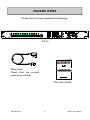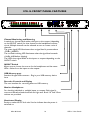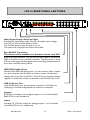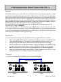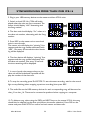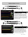
1
ICE-16
USER GUIDE
Publication AP8900
CONTENTS
Warranty ....................................................................................
4
Conformity Statement ............................................................
5
Safety Instructions ....................................................................
6
Packed Items Checklist ...........................................................
9
Introduction to ICE-16 ...........................................................
10
Applications Drawings ............................................................
11
Front Panel Controls & Features .........................................
14
Rear Panel Features .................................................................
15
USB Direct Recording Quickstart .......................................
16
Recording to USB Memory—Important Notes...............
17
USB Memory Initialisation and Formatting........................
18
USB Recording Front Panel Controls.................................
19
Recording to USB Memory—Further Notes ...................
20
USB Memory File Structure ..................................................
21
Playlist Mode ..............................................................................
22
FireWire Driver—Installation (PC).....................................
23
FireWire Driver—Control Panel (PC) ..............................
24
USB Driver—Installation (PC)..............................................
26
USB Driver—Control Panel (PC)........................................
27
Connecting to a Mac computer ...........................................
29
USB Memory Recording—Synchronising units ................
31
Connecting Mixing Consoles to ICE-16.............................
33
Specifications..............................................................................
34
Dimensions & Weights ...........................................................
36
Block Diagram ...........................................................................
37
Allen & Heath
3
ICE-16 User Guide
WARRANTY
Limited One Year Warranty
This product is warranted to be free from defects in materials or
workmanship for period of one year from the date of purchase by the
original owner.
To ensure a high level of performance and reliability for which this
equipment has been designed and manufactured, read this User Guide
before operating. In the event of a failure, notify and return the defective
unit to ALLEN & HEATH Limited or its authorised agent as soon as
possible for repair under warranty subject to the following conditions
Conditions Of Warranty
The equipment has been installed and operated in accordance with the
instructions in this User Guide.
The equipment has not been subject to misuse either intended or
accidental, neglect, or alteration other than as described in the User
Guide or Service Manual, or approved by ALLEN & HEATH.
Any necessary adjustment, alteration or repair has been carried out by
ALLEN & HEATH or its authorised agent.
The defective unit is to be returned carriage prepaid to ALLEN & HEATH
or its authorised agent with proof of purchase.
Units returned should be packed to avoid transit damage.
In certain territories the terms may vary.
Check with your ALLEN & HEATH agent for any additional warranty
which may apply.
http://www.allen-heath.com
Allen & Heath
4
ICE-16 User Guide
EMC & SAFETY
This product complies with the European Electro magnetic
Compatibility directives 2004/108/EC and the European Low Voltage
Directives 2006/95/EC.
This product has been tested to EN55103 Parts 1 & 2 2009 for use
in Environments E1, E2, E3, and E4 to demonstrate compliance with
the protection requirements in the European EMC directive
2004/108/EC. During some tests the specified performance figures
of the product were affected. This is considered permissible and the
product has been passed as acceptable for its intended use. Allen &
Heath has a strict policy of ensuring all products are tested to the
latest safety and EMC standards. Customers requiring more
information about EMC and safety issues can contact Allen & Heath.
NOTE: Any changes or modifications to the product not approved
by Allen & Heath could void the compliance of the product and
therefore the users authority to operate it.
ICE-16 User Guide AP8900 Issue 2
Copyright © 2014 Allen & Heath Limited. All rights reserved
Allen & Heath Limited
Kernick Industrial Estate, Penryn, Cornwall, TR10 9LU, UK
http://www.allen-heath.com
Allen & Heath
5
ICE-16 User Guide
SAFETY INSTRUCTIONS
WARNING - Read the following before proceeding :
CAUTION
ATTENTION: RISQUE DE CHOC ELECTRIQUE – NE PAS OUVRIR
!
WARNING: This equipment must be earthed.
Read instructions:
Retain these safety and operating instructions for future
reference. Adhere to all warnings printed here and on
the product. Follow the operating instructions printed in
this User Guide.
Do not remove cover:
Operate the product with its covers correctly fitted.
Power sources:
Connect the product to a mains power unit only of the
type described in this User Guide and marked on the
rear panel. Use the power cord with sealed mains plug
appropriate for your local mains supply as provided
with the product. If the provided plug does not fit into
your outlet consult your service agent for assistance.
Power cord routing:
Route the power cord so that it is not likely to be walked
on, stretched or pinched by items placed upon or
against it.
Grounding:
Do not defeat the grounding and polarisation means of
the power cord plug. Do not remove or tamper with the
ground connection in the power cord.
Allen & Heath
6
ICE-16 User Guide
SAFETY INSTRUCTIONS
Water and moisture:
To reduce the risk of fire or electric shock do not expose the product to rain or moisture or use it in damp
or wet conditions. Do not place containers of liquids on
it which might spill into any openings.
Ventilation:
Do not obstruct the ventilation slots or position the
product where the air flow required for ventilation is
impeded. If the product is to be operated in a rack unit
or flightcase ensure that it is constructed to allow adequate ventilation.
Heat and vibration:
Do not locate the product in a place subject to excessive heat or direct sunlight as this could be a fire hazard. Locate the product away from any equipment
which produces heat or causes excessive vibration.
Servicing:
Switch off the equipment and unplug the power cord
immediately if it is exposed to moisture, spilled liquid,
objects fallen into the openings, the power cord or plug
become damaged, during lightening storms, or if
smoke, odour or noise is noticed. Refer servicing to
qualified technical personnel only.
Installation:
Install the product in accordance with the instructions
printed in this User Guide. Do not connect the output of
power amplifiers directly to the product.
Use audio
connectors and plugs only for their intended purpose.
Important Mains plug wiring instructions
The product is supplied with a moulded mains plug fitted to the AC mains power lead.
Follow the instructions below if the mains plug has to be replaced. The wires in the
mains lead are coloured in accordance with the following code:
TERMINAL
L
N
E
LIVE
NEUTRAL
EARTH GND
WIRE COLOUR
European
USA/Canada
BROWN
BLACK
BLUE
WHITE
GREEN & YELLOW GREEN
The wire which is coloured Green and Yellow must be connected to the terminal in the plug
which is marked with the letter E or with the Earth symbol. This appliance must be earthed.
The wire which is coloured Blue must be connected to the terminal in the plug which is
marked with the letter N.
The wire which is coloured Brown must be connected to the terminal in the plug which is
marked with the letter L.
Ensure that these colour codes are followed carefully in the event of the plug being changed.
Allen & Heath
7
ICE-16 User Guide
SAFETY INSTRUCTIONS
General Precautions:
Damage :
Environment :
Cleaning :
Transporting :
Hearing :
82
Allen & Heath
To prevent damage to the controls and cosmetics
avoid placing heavy objects on the control surface, scratching the surface with sharp objects, or
rough handling and vibration.
Protect from excessive dirt, dust, heat and vibration when operating and storing. Avoid tobacco
ash, smoke, drinks spillage, and exposure to rain
and moisture. If the product becomes wet, switch
off and remove mains power immediately. Allow to
dry out thoroughly before using again.
Avoid the use of chemicals, abrasives or solvents.
The front panel is best cleaned with a soft brush
and dry lint-free cloth. The switches and potentiometers are lubricated for life. The use of electrical
lubricants on these parts is not recommended.
Protect the controls from damage during transit.
Use adequate packing if you need to ship the unit.
To avoid damage to your hearing do not operate
any sound system at excessively high volume.
This applies particularly to close-to-ear monitoring
such as headphones and in-ear systems. Continued exposure to high volume sound can cause
frequency selective or wide range hearing loss.
8
ICE-16 User Guide
PACKED ITEMS
Check that you have received the following:
ALLEN&HEATH
TIME
Hi Level
Signal
PHONES/MONITOR
OUT
Record
MONITOR SEL
1
2
3
4
5
6
7
8
9
10
11
12
13
14
15
16
IN/OUT MONITOR
USB DRIVE
DEL
PREV
NEXT
PLAY/STOP
REC
M ONITOR LEVEL
ICE-16
Mains Lead
Check that the correct
mains plug is fitted.
This User Guide!
Allen & Heath
9
ICE-16 User Guide
INTRODUCTION TO THE ICE-16
Background Overview:
The Allen & Heath ICE-16 was designed to make life easier when it comes to recording multiple audio sources. Experience of struggling with boot-up and set up
times when recording to a laptop at shows, and choosing the right converter unit
made us think that there is a real need for a straightforward multi-channel analogue
input capture unit that is both easy to use and high quality. So the ICE-16 was born.
Multi-application:
The primary aim for the ICE-16 was to capture multiple channels of audio from an
analogue mixer or other source of line level audio signals but it has so many more
application possibilities. In addition to recording straight to a USB memory device,
the ICE-16 can stream multi-channel audio in high resolution 24bit, up to 96kHz
sample rate, to and from a computer so you can use the ICE-16 in a studio environment as well as live sound or event recording. In fact, if you were wondering where
the name ICE came from, here is the explanation:
Interface
-
Capture
-
Expand
Interface: The ICE-16 can function as a multi-channel analogue to digital and digital
to analogue converter, connecting 24 bit audio at up to 96kHz sample rate to a
computer via either IEEE1394 FireWire or USB-2.0. This is ideal for studio environments where analogue signals are converted and sent to a computer for recording
to a Digital Audio Workstation (DAW).
Capture: Record 16 channels of audio in either 16 or 24 bit resolution (depending
on the USB memory speed) at up to 48kHz sample rate, (96kHz with 8 channels)
directly to a USB memory device—either a USB hard drive or memory stick.
The recorded file format is .wav.
Expand: You can link ICE-16 units together in different ways. You can daisy chain
two units together using the FireWire ports in order to expand the number of
channels connected to a computer. Or you can link two or more units together
using the Sync ports in order to synchronise more than one ICE-16 when recording
multiple channels,
Allen & Heath
10
ICE-16 User Guide
APPLICATION: RECORDING TO USB MEMORY
Mics & Instruments
Into console.
Direct outs or to Line Inputs on ICE-16
DI R O UT
DI R OU T
1
DI R OU T
2
MIC 1
D I R OU T
3
MIC 2
D I R OU T
4
MIC 3
DR
I OU T
5
MI C 4
DR
I OUT
6
MI C 5
DR
I OUT
7
MI C 6
DR
I O UT
8
MI C 7
DI R O UT
9
MI C 8
DI R O UT
10
MIC 9
DI R OU T
11
MIC 10
DI R OU T
12
MIC 11
D I R OU T
13
MIC 12
DR
I OUT
DR
I OU T
14
MIC 13
15
MI C 14
16
MI C 15
ST 1 I N
MI C 16
AU X OU T
ST 3 I N
L
L
R
R
AU X 1
A UX
2
G RP
2
A UX
3
AU X 4
AU X 5
AU X 6
MA N
I O UT
L
N
I SER T L
G RO UP O UT
GR P 1
G RP
3
2T RK I N
G RP 4
L
48V
48V
LI NE I N
48V
LI NE I N
1
48V
48V
4 8V
LIN E N
I
LN
I EN
I
LN
I EN
I
3
4
5
N
I SER T
I N SER T
I N SER T
2
48 V
LN
I EN
I
48 V
48 V
48 V
48V
48V
48V
48V
4 8V
4 8V
L/M
LI NE I N
LI NE I N
LIN E I N
I
LIN E N
I
LN
I EN
I
LN
I EN
LI NE N
I
7
8
9
10
11
12
13
14
15
16
I NS ERT
I NS ERT
I NS ERT
N
I SE RT
N
I SE RT
N
I SER T
N
I SER T
I N SER T
I NS ER T
I NS ERT
LI NE I N
6
LI NE I N
LI NE I N
N
I SER T
1
2
3
4
I NS ER T
5
6
7
8
9
10
11
12
13
14
15
1
I NS ERT
ST2
ST4
N
I
2
N
I SE RT
3
N
I SER T
R
R
N
I SER T 4
N
I
R
N
I SE RT
N
I SER T R
L /M
M
2 TRK OUT
R
MTX 1
L
2
MTX
16
USB
MA TR XI
O UT
ST ERE O I NPU TS
N
I SER T M
R TE U RN
SEND
R
P HO NE S
0
G AI N
10
20
30
0
10
-6
20
30
- 15
HM
- 15
+15
LM
HM
- 15
+15
15k
180
70
400
1k
GA N
I
20
30
HM
500Hz
- 15
15k
180
20
HM
500Hz
-1 5
15k
180
HM
-1 5
+ 15
500Hz
HM
-1 5
+ 15
500Hz
-1 5
+ 15
G AI N
- 15
+ 15
G AI N
- 15
- 15
+15
0
10
G AI N
40
- 15
LM
HM
- 15
+15
LM
HM
- 15
+15
- 15
HM
+15
- 15
G AIN
HM
+15
GA N
I
500Hz
-1 5
15k
180
HM
-1 5
+ 15
LEV
500Hz
-1 5
HM
500Hz
LF
80Hz
80Hz
- 15
+15
+15
+6
AU X2
+ 15
+6
OO
+6
OO
+6
- 15
+ 15
- 15
+ 15
+6
+6
O
+6
+6
-1 5
-1 5
+6
+ 15
+6
A UX 2
+6
OO
+6
OO
+6
+6
+15
+15
+6
+15
+6
OO
+6
OO
+6
+15
+6
OO
+6
OO
+6
-1 5
+ 15
+6
OO
+6
OO
+6
HF
+ 15
+15
- 15
+15
AU X4
AU X4
+6
OO
AU X4
OO
+6
+6
O
+6
-1 5
-1 5
+6
+6
O
+6
+ 15
+6
+6
OO
+6
OO
+6
+6
P OS T
P RE
A UX 5
POST
OO
O
+6
AU X6
POST
O
+6
AU X6
PO TS
O
+6
AU X6
POST
OO
+6
A UX 6
POST
OO
+6
A UX 6
POST
OO
+6
A UX 6
POST
OO
+6
A UX6
POST
OO
+6
A UX6
POST
OO
+6
AU X6
POST
OO
+6
AU X6
POST
O
+6
AU X6
PO TS
O
+6
AU X6
PO TS
OO
+6
OO
+6
+6
+6
OO
+6
+ 16
+9
+6
+3
+6
+3
0
-3
0
-3
6-9
-6
-9
SYNC
O UT
1
2
3
4
5
6
7
8
9
10
11
12
13
14
15
16
1
2
3
4
5
6
7
8
9
10
11
12
13
14
15
16
ON
FireWire
See under side for sa fe ty w ar nings.
A
B
USB
OUTPUTS
INPUTS
- 12
- 16
- 20
- 30
- 20
- 30
L
PFL
AC MAINS IN ~
100 - 240V~ 47-63Hz 2 0W MAX
R
P FL/ AF L ACTI VE
ALLEN&HEATH
AU X2
0
+16
+9
- 12
- 16
+6
+6
A FL
2
MATR XI
AU X1
+10
0
OO
A UX 3
0
OO
A UX4
+ 10
0
OO
+ 10
A FL
L-R
M
AF L
L-R
M
=
OO
+ 10
A FL
L-R
+6
P OST
P RE
POST
AU X5
0
+10
AU X6
0
+ 10
AF L
M N
I
MAX
LR
M
=
P AN
ALLEN&HEATH
P HO NE S
L EVE L
M
=
OO
AFL
L-R
M
=
P AN
OO
P AN
POST
L
R
L
R
L
R
L
TIME
H i Level
+6
A UX6
POST
OO
A FL
A UX5
+6
A UX6
POST
OO
PLA YBA CK
To LR
OO
A FL
+6
OO
P OST
P RE
OO
+6
A UX 6
POST
+6
LEV EL
OO
MAT RI X 1
OO
A UX4
OO
POST
OO
+6
A UX 6
POST
P LA YBA CK
L EVE L
+ 15
EQ N
I
A UX5
POST
O
+6
AU X6
POST
+6
PRE
P OST
P RE
A UX 5
POST
OO
M
LEV EL
- 15
OFF
P OWER
A UX3
A UX4
OO
+6
PO ST
PRE
AU X5
POST
A UX 4
O
+6
PO ST
PR E
AU X5
PO TS
A UX 4
O
+6
PO ST
PR E
AU X5
PO TS
AU X4
O
+6
PO ST
PR E
AU X5
POST
AU X4
OO
+6
PO ST
PR E
AU X5
POST
AU X4
OO
+6
PO ST
PR E
A UX5
POST
+6
IN
FUSE
T1.0AL 250V
20mm
Tal kt o LRM
AU X
5-6
LR
p re f- ade
A l u p =LR post
+6
PAN
+6
OO
AU X6
+6
A UX2
PRE
A UX3
OO
+6
OO
R
M
M AX
Tal k ot A UX 1-4
AU X
1-2
OO
L
OO
PRE
OO
A UX2
+6
A UX 3
+6
OO
R
A UX1
PRE
+6
PRE
OO
+ 15
EQ N
I
A UX1
OO
A UX 2
PRE
A UX 3
- 15
80Hz
- 15
+ 15
PRE
O
O
A UX 2
4
OO
L
M N
I
MTX
1-2
+6
LF
E QN
I
A UX 1
PRE
+6
AU X3
+ 15
250Hz
+15
80Hz
+ 15
E QN
I
A UX 1
+6
+6
O
PRE
AU X3
+ 15
- 15
2k5
LM
LF
80Hz
+ 15
E QN
I
O
O
AU X2
PRE
AU X3
AU X4
OO
+6
P OST
P RE
A UX5
POST
AU X4
OO
+6
P OST
P RE
A UX 5
POST
A UX4
OO
+6
P OS T
P RE
A UX 5
POST
A UX4
OO
+6
P OS T
P RE
A UX 5
POST
+6
A UX 4
OO
+6
P OS T
P RE
AU X5
POST
A UX 4
O
+6
PO ST
PR E
AU X5
PO TS
A UX 4
O
+6
PO ST
PR E
AU X5
POST
AU X4
O
+6
PO ST
PR E
AU X5
OO
+6
U SB S END SOU RC E
OO
4
- 15
HM
LM
TB MI C
TB
L EVE L
+6
3
GR P
OO
OO
PL AY BAC K SO UR CE
OO
GR P
+6
12k
- 15
2k5
400
-1 5
LF
2 TRK
U SB
+6
2
+6
GR P
HF
12k
HM
250
1k
OO
GR P
OO
3
10
OO
+ 15
35Hz
+6
2
GR P
5
S T3 N
I
U SB
1
OO
0
O
GR P
1
GR P
-5
- 30
15k
180
45
LM
80Hz
-1 5
PRE
O
O
AU X2
PRE
AU X3
AU X1
PRE
OO
AU X2
PRE
LF
80Hz
+15
EQ I N
AU X1
PRE
OO
AU X2
PRE
AU X3
- 15
EQ I N
AU X1
PRE
OO
AU X2
LF
80Hz
- 15
EQ I N
AU X1
PRE
+6
OO
A UX3
LF
80Hz
- 15
EQ I N
AU X1
+6
OO
PRE
A UX3
LF
80Hz
- 15
EQ I N
OO
A UX2
PRE
OO
A UX 3
LF
80Hz
- 15
PRE
OO
A UX2
PRE
+6
A UX 3
A UX1
PRE
OO
+6
PRE
OO
+ 15
EQ N
I
A UX1
PRE
OO
A UX 2
LF
80Hz
- 15
EQ N
I
A UX 1
PRE
+6
+6
O
PRE
A UX 3
LF
80Hz
+ 15
E QN
I
A UX 1
O
O
A UX 2
AU X3
LF
80Hz
+ 15
E QN
I
PRE
+6
+6
O
PRE
AU X3
LF
80Hz
-1 5
A UX 1
O
O
AU X2
PRE
AU X3
LF
80Hz
EQ I N
AU X1
PRE
O
O
AU X2
PRE
LF
80Hz
EQ I N
PRE
OO
AU X2
PRE
AU X3
LF
AU X1
PRE
+6
+6
OO
- 15
EQ I N
AU X1
PRE
OO
+ 15
80Hz
- 15
EQ I N
AU X1
OO
- 15
GR P
5
10
ToLR
T o CH
-1 0
LEV-2 0
5
10
- 15
LF
0
O
0
O
250Hz
LF
ST 3 N
I PU T SOU RC E
-5
- 30
ST 4
-5
- 30
4k
70
400
-1 0
-2 0
5
10
ToLR
T o CH
+15
6k
-1 5
250
L EV
0
O
-1 0
LEV- 20
+ 15
1k
ST 3
-5
- 30
ST2
3k
700
15k
180
35Hz
-1 0
- 20
100Hz
- 15
1k
6k
45
LM
ST1
10
63 26
HPF
12k
4k
70
400
30
50
-6
HF
250
1k
20
40
- 10
+15
700
+ 15
35Hz
10
0
MI C
LN
IE
63 26
HP F
100Hz
3k
1k
6k
45
LM
0
10
50
-6
- 15
4k
70
400
- 15
30
40
-1 0
12k
250
1k
20
LN
IE
26
HF
+15
35Hz
10
0
MI C
50
+15
3k
700
15k
180
45
LM
0
10
63
HP F
100Hz
- 15
1k
6k
70
400
- 15
30
-6
+ 15
4k
500Hz
250
1k
20
40
-1 0
12k
+15
35Hz
10
0
MI C
LN
IE
26
HF
3k
700
15k
180
45
LM
G AIN
40
- 15
1k
6k
70
400
1k
0
10
63
HP F
100Hz
+ 15
4k
500Hz
250
35Hz
30
50
- 10 - 6
12k
+15
45
20
0
M C
I
LN
I E
HF
3k
700
15k
180
70
400
10
G AI N
40
-1 5
1k
6k
- 15
250
1k
0
10
63 26
HP F
100Hz
+ 15
4k
500Hz
+15
35Hz
30
50
- 10 - 6
12k
3k
700
15k
180
70
20
L I NE
HF
-1 5
1k
6k
45
10
0
M C
I
50
63 26
100 Hz
+ 15
4k
500 Hz
HM
250
400
30
H PF
12k
+15
1k
20
- 10 - 6
HF
3k
700
15k
180
35Hz
10
0
M C
I
L I NE
100H
z
-1 5
1k
6k
45
LM
0
10
63 26
H PF
12k
+ 15
4k
70
400
30
50
-6
HF
3k
500H
z
HM
250
1k
20
40
- 10
100Hz
+ 15
35Hz
10
0
M C
I
L I NE
63 26
H PF
-1 5
1k
700
15k
180
45
LM
0
10
50
-6
12k
4k
70
400
30
40
- 10
+15
6k
- 15
250
1k
20
L I NE
HF
3k
500Hz
HM
+ 15
35Hz
10
0
MI C
50
- 15
1k
700
15k
180
45
LM
GA N
I
40
100Hz
+15
4k
70
400
0
10
30
63 26
H PF
12k
3k
6k
-1 5
250
1k
20
-6
HF
+ 15
35Hz
10
0
MI C
- 10
100Hz
- 15
1k
700
15k
180
45
LM
GA N
I
L I NE
63 26
H PF
12k
70
400
0
10
30
50
-6
HF
4k
6k
-1 5
250
1k
20
40
- 10
+15
700
+ 15
35Hz
10
0
MI C
LN
IE
100Hz
3k
1k
6k
45
LM
GA N
I
63 26
H PF
- 15
4k
70
400
0
10
50
-6
12k
+ 15
1k
30
40
-1 0
HF
+15
3k
700
250
35Hz
10
0
MI C
LN
IE
63 26
HP F
100Hz
- 15
1k
6k
45
LM
GA N
I
50
-6
+15
4k
70
400
1k
0
10
40
-1 0
12k
250
35Hz
10
0
MI C
LN
IE
26
HF
3k
700
+ 15
45
LM
0
10
63
HP F
100Hz
- 15
1k
6k
- 15
250
35Hz
30
50
-6
+ 15
4k
500Hz
+15
45
3k
700
15k
180
70
400
20
40
-1 0
HF
- 15
1k
6k
- 15
250
1k
10
0
M C
I
LN
IE
26
12k
+ 15
4k
500Hz
+15
35Hz
3k
1k
700
15k
180
70
45
LM
-1 5
4k
500 Hz
HM
0
G AIN
40
12k
+ 15
6k
10
63
HP F
100Hz
HF
12k
3k
50
- 10 - 6
100 Hz
HF
-1 5
30
LN
IE
63 26
H PF
100H
z
12k
1k
20
0
M C
I
50
- 10 - 6
H PF
HF
700
10
G AI N
40
M C
I
LN
I E
63 26
0
10
0
40
50
- 10
10
G AI N
0
MC
I
LI NE
Signal
R
P HO NE S/MO NITOR
O UT
Record
+6
OO
OO
=
+6
O
=
P AN
R
EVEN
MUT E
R
EVEN
L
ODD
MUT E
P FL
PFL
SIG
PFL
PFL
PFL
P FL
P FL
P FL
PFL
PFL
PFL
PFL
PFL
PK!
+6
PK!
+6
0
SIG
0
SI G
0
SI G
0
SIG
0
SI G
0
SIG
2
3
4
L
R
M
A FL
MU TE
A FL
10
0
5
5
5
5
10
10
10
10
20
20
20
20
20
20
1-2
5
5
3 -4
3-4
10
10
20
20
30
30
OO
1
OO
2
3
20
20
30
30
30
30
30
30
30
30
OO
OO
OO
OO
OO
OO
OO
OO
4
5
6
7
8
9
10
20
20
30
30
OO
11
20
OO
12
13
20
20
20
10
5
1 -2
3 -4
20
10
10
10
1 -2
3-4
M
0
5
1-2
3-4
20
10
M
20
5
5
0
30
30
30
30
30
30
30
30
30
30
30
30
OO
OO
OO
OO
OO
OO
OO
OO
OO
OO
OO
OO
16
17-18
3
4
5
6
7
8
9
10
11
12
13
14
15
16
IN /O UT MO NITO R
U SB D RIVE
DEL
PREV
NEXT
PLAY/ STOP
REC
MO NITO R LEV EL
0
30
15
2
5
0
OO
14
1
AF L
0
1-2
3-4
20
MUTE
5
1-2
3-4
20
MUTE
10
1-2
3-4
20
PK!
+6
MUTE
5
0
1-2
3-4
20
MUT E
10
1-2
3-4
20
0
10
5
L-R
1-2
20
MU TE
A FL
1 -2
M
PK!
+6
MO NITO R S EL
MU TE
3 -4
M
PK!
+6
SIG
10
L -R
0
PK!
+6
1
PK !
SIG
10
L -R
PK!
+6
0
SIG
1 -2
M
0
P FL
PK !
SIG
10
MU TE
P FL
PFL
L-R
R
EVEN
L
ODD
3 -4
M
0
=
BAL
R
EVEN
MU TE
PK !
SI G
10
L-R
+6
OO
=
L
ODD
3-4
M
0
+6
OO
BA L
R
EVEN
MU TE
PK !
SI G
10
L-R
+6
=
L
ODD
1-2
M
0
OO
PAN
R
EVEN
MU TE
PK !
SI G
10
L-R
+6
=
L
ODD
3-4
M
0
O
PA N
R
EVEN
MUTE
PK !
SI G
10
L-R
+6
=
L
O DD
1-2
M
0
O
PA N
R
EVEN
MUTE
PK !
SI G
10
L-R
+6
=
L
ODD
3-4
M
0
O
PA N
R
EVEN
MUTE
PK !
SIG
10
L-R
+6
=
L
ODD
1-2
M
0
OO
P AN
R
EVEN
MU TE
PK !
SIG
10
L -R
+6
=
L
ODD
3-4
M
0
OO
P AN
R
EVEN
MU TE
PK !
SIG
10
L -R
+6
=
L
ODD
1-2
M
0
OO
P AN
R
EVEN
MU TE
PK !
SIG
10
L-R
+6
=
L
ODD
3-4
M
0
OO
P AN
R
EVEN
MU TE
PK !
SIG
10
L-R
+6
=
L
ODD
1-2
M
0
OO
PAN
R
EVEN
MU TE
PK !
SIG
10
L-R
+6
=
L
ODD
3-4
M
0
OO
PAN
R
EVEN
MU TE
PK !
SI G
10
+6
=
L
ODD
MUTE
PFL
L-R
OO
PAN
R
EVEN
1-2
M
0
+6
=
L
O DD
PK !
SI G
10
O
PA N
R
EVEN
MUTE
PFL
L-R
0
L
ODD
PK !
SI G
10
+6
=
PA N
R
EVEN
MUTE
PK !
L-R
O
P AN
L
ODD
PK !
+6
=
P AN
L
ODD
19- 20
GR P 1
GR P 2
GR P 3
G RP
4
L
R
USB Memory stick or
Drive
M
ICE-16
Mixing console
Go to page 16 for Quickstart
Allen & Heath
11
ICE-16 User Guide
APPLICATION: VIRTUAL SOUNDCHECK
Using ICE-16 for a Soundcheck
With pre-recorded instruments, vocals and drum
sounds in your multi-channel Song folders, you can
use ICE-16 to play individual channels to the line
inputs of a mixing console so that you can set eq,
monitor sends and create a mix even before the
band arrives, leaving you to set the levels for the
microphones and plug them into the designated
channels on the console.
ICE-16 outputs to console line inputs
D I R O UT
DR
I OU T
1
MI C 1
PA & Monitors
D I R OU T
2
DI R O UT
3
MIC 2
DR
I OU T
4
MI C 3
D I R O UT
5
MIC 4
DR
I O UT
6
MI C 5
DR
I OU T
7
MI C 6
DI R O UT
8
MIC 7
DR
I OU T
D I R O UT
DR
I O UT
10
11
12
9
MI C 8
MIC 9
MI C 10
MI C 11
D I R OU T
DI R O UT
13
MIC 12
MI C 13
D I R O UT
DR
I OU T
14
15
MIC 14
A UX O U T
16
15
MIC
ST1 NI
MI C 16
ST3
N
I
L
L
R
R
L/ M
L/ M
A UX
1
G RP
1
A UX
2
AU X 3
AU X 4
A UX
5
AU X 6
MAI N O UT
L
I N SER T L
G R O UP O UT
2TR K I N
GRP 2
GR P 3
GR P 4
I NS ER T 2
I N SER T 3
I N SER T 4
L
48V
48 V
I
LN
I EN
4 8V
LI NE I N
1
48V
I
LN
I EN
2
48 V
LI NE I N
3
4 8V
I
LI NE N
4
48 V
I
LN
I EN
5
4 8V
LI NE I N
6
48V
I
LI N E N
7
4 8V
LI NE I N
8
4 8V
48V
4 8V
48V
4 8V
48 V
LI NE I N
I
LN
I EN
LI NE I N
I
LN
I EN
LIN E I N
LI NE I N
I
LN
I EN
10
11
12
13
14
15
16
9
ST2 I N
I NS ER T
1
I N SER T
2
N
I SE RT
3
I NS ER T
4
I N SER T
5
I NS ERT
6
I NS ER T
7
N
I SE RT
8
I NS ER T
9
I N SE RT
10
I NS ERT
11
I N SER T
12
N
I SE RT
13
2T RK O UT
R
MT X 1
I N SER T
I NS ER T
14
15
R
ST4 NI
R
I N SER T
R
I N SER T R
1
N
I SE RT
M
I N SER T M
L
MT X 2
16
MAT RI X
OU T
STE RE O I NP UTS
USB
RETUR N
SEND
R
P HO N ES
GA N
I
0
MI C
LI NE
0
10
10 20 30
40
50
- 10 - 6
63 26
0
10
10 20 30
G AI N
40
0
MIC
50
LINE
-10 -6
63 26
HP F
SYNC
IN
FUSE
1
2
3
4
5
6
7
1
8
2
3
4
5
6
7
- 15
4k
3k
15k
700
HM
50
63 26
3k
50
63 26
3k
3k
HM
- 15
4k
3k
50
63 26
HM
50
63 26
3k
3k
- 15
4k
700
50
63 26
HM
HM
3k
- 15
3k
- 15
4k
700
3k
50
63 26
15k
50
63 26
3k
50
63 26
- 15
3k
15k
3k
- 15
4k
3k
5
ON
180
AC MAINS IN ~
LM
9
100 - 24 0V~ 47-63Hz 20W MAX
FireWire
See under side for s af ety wa rnings .
A
10
11
USB
B
12
13
14
15
16
9
10
11
OUTPUTS
12
13
14
15
- 15
+ 15
70
250
35Hz
180
70
400
45
1k
LM
- 15
+15
250
35Hz
180
1k
250
35Hz
180
70
400
45
LM
- 15
+ 15
70
400
45
1k
LM
- 15
+15
250
35Hz
180
70
400
45
1k
LM
- 15
+15
250
35Hz
180
1k
250
35Hz
180
70
400
45
LM
- 15
+ 15
70
400
45
1k
LM
- 15
+15
250
35Hz
180
1k
-1 5
+ 15
70
400
45
250
LM
35Hz
180
70
400
45
1k
LM
- 15
+ 15
250
35Hz
180
70
400
45
1k
LM
-1 5
+15
250
35Hz
180
1k
250
35Hz
180
70
400
45
LM
- 15
+ 15
70
400
45
1k
LM
- 15
+15
250
35Hz
180
1k
250
35Hz
180
70
400
45
LM
-1 5
+ 15
70
400
45
1k
LM
- 15
+ 15
250
35Hz
180
70
400
45
HM
1k
250
L EV-20
5
LM
35Hz
1k
250
- 15
+ 15
LF
- 15
+15
LF
- 15
+ 15
- 15
LF
+15
LF
- 15
+15
LF
- 15
+ 15
LF
- 15
+15
LF
- 15
+ 15
-1 5
LF
+ 15
LF
- 15
+15
-1 5
LF
+ 15
LF
- 15
+15
LF
- 15
+ 15
LF
-1 5
+ 15
-1 5
+ 15
LF
- 15
LM
+15
LF
35Hz
GRP
5
- 15
+ 15
80Hz
- 15
+15
E QIN
+6
OO
+ 15
+15
-1 5
+15
+ 15
+15
+6
+6
O
OO
+6
OO
+6
A UX3
+6
OO
OO
A UX 4
O
OO
OO
O
OO
O
OO
OO
O
OO
OO
+15
+6
OO
OO
A UX 6
PHONES /MONIT OR
Recor d
=
2
3
4
5
6
7
8
9
10
11
12
13
14
15
16
IN/OUT MONITOR
=
DEL
P REV
NEXT
P LAY /STOP
REC
MONITOR LEVE L
R
EVEN
L
ODD
MUTE
PFL
O
=
R
EVEN
L
OD D
M UTE
PF L
PFL
PK !
L
ODD
R
EVEN
L
ODD
L
ODD
M UTE
P FL
PFL
L
ODD
P FL
L
O DD
OO
R
EVEN
L
ODD
+6
OO
+6
R
EVEN
L
ODD
P FL
L
ODD
R
EVEN
L
ODD
R
EVEN
L
OD D
M UTE
PF L
0
R
EVEN
L
ODD
MUT E
P FL
PFL
L
ODD
P FL
PK !
SIG
SI G
SIG
SI G
SI G
SIG
SI G
SIG
SI G
SI G
SIG
SI G
10
10
10
10
10
10
10
10
10
10
10
AFL
R
MI N
R
+6
+6
+6
0
SI G
0
SIG
0
SI G
1
2
3
4
L
R
MU TE
A FL
M UTE
AFL
MUTE
AFL
MU TE
PK!
PK!
PK!
+6
MU TE
+6
0
SI G
M
MUT E
10
MU TE
AF L
L -R
10
10
10
10
10
10
5
5
5
5
5
5
5
M
0
0
0
0
0
1-2
1-2
1 -2
1-2
1-2
1 -2
1-2
1 -2
1-2
1 -2
5
5
5
5
5
5
5
3-4
3-4
3 -4
3-4
3-4
3 -4
3-4
3 -4
3-4
3 -4
10
10
10
10
10
10
M
M
0
10
3-4
M
0
0
20
20
20
20
20
20
20
20
20
20
20
20
20
20
20
20
20
20
20
20
20
20
20
20
30
30
30
30
30
30
30
30
30
30
30
30
30
30
30
30
30
30
30
30
30
30
30
30
OO
OO
2
OO
3
OO
4
OO
5
OO
6
OO
7
OO
8
OO
9
OO
10
OO
11
OO
12
OO
13
OO
14
OO
15
OO
16
OO
17-18
OO
19-20
OO
GR P 1
OO
G RP 2
OO
G RP 3
OO
GRP 4
Mixing console
12
MAX
LR
M
L
PK!
PK!
0
SIG
1-2
1
ICE-16
AF L
P HO NE S
L EVEL
M
=
PA N
L
+6
PK !
L-R
0
R
PK!
0
SIG
3-4
M
0
A FL
L-R
M
=
PA N
L
0
SIG
1-2
M
0
P FL
R
PK!
+6
3 -4
M
0
AF L
L -R
M
+ 10
1 -2
M
0
0
OO
3-4
M
0
AU X6
1-2
M
0
AFL
L-R
=
PAN
+10
3 -4
M
0
0
OO
SIG
10
L -R
A UX 5
1 -2
M
0
L-R
+ 10
3 -4
M
0
L -R
0
OO
1 -2
M
0
L-R
A UX4
3-4
M
0
L-R
+10
1-2
M
0
L -R
0
OO
3 -4
M
0
L-R
AU X3
1 -2
M
0
L-R
M UTE
PF L
PK !
SIG
+6
R
EVEN
L
ODD
MUT E
PFL
PK !
+10
M
L
=
R
EVEN
L
O DD
10
L-R
PK !
R
EVEN
- 30
R
P FL/ AF L ACTI VE
+6
OO
+6
BAL
MUTE
SIG
L-R
PK !
R
EVEN
- 16
- 20
- 30
L
0
O
=
OO
POST
=
BA L
MU TE
AU X2
L-R
POST
O
+6
10
L -R
PK !
=
PAN
-6
-9
- 12
- 16
- 20
PF L
ALLEN&HEATH
A UX 6
POST
OO
+6
+6
AU X6
POST
=
P AN
0
-3
-9
- 12
+6
PLA YB AC K
To LR
A FL
+6
P OS T
P RE
A UX 5
O
+6
A UX 6
OO
+6
SIG
L-R
PK !
=
+6
+3
0
-3
O
+6
AFL
+ 10
+6
OO
+6
PO ST
PR E
AU X5
POST
OO
+6
PO TS
OO
+6
PA N
MU TE
PFL
PK !
=
P AN
10
L -R
PK !
R
EVEN
MUTE
OO
AU X6
POST
OO
+6
+6
A UX 6
POST
=
+6
OO
MAT RI X 2
A U X1
A UX 4
O
P OS T
P RE
POST
OO
LEV EL
+6
A FL
OO
AU X4
+6
A UX 5
PO TS
OO
+6
A UX6
O
+6
PA N
MU TE
PFL
PK !
=
+16
+9
+6
+3
P LA YBA CK
L EVE L
-6
+6
O
+6
OO
PO ST
PR E
AU X5
POST
OO
+6
AU X6
POST
OO
+6
PAN
MUT E
P FL
PK !
=
P AN
SI G
L-R
PK !
R
EVEN
MU TE
O
+6
POST
OO
+6
10
L-R
PK !
=
PA N
MU TE
OO
A UX 6
PO TS
O
+6
+6
AU X6
POST
=
P AN
R
EVEN
OO
+6
A U X6
OO
+6
SIG
0
PK !
=
R
EVEN
O
+6
POST
O
+6
PA N
MU TE
PFL
PK !
=
PAN
MUT E
OO
A UX6
POST
OO
+6
+6
AU X6
POST
=
P AN
R
EVEN
O
+6
A UX 6
OO
+6
P OWER
A UX 3
10
L -R
Allen & Heath
L
ODD
OO
+6
AU X6
PO TS
O
+6
PA N
MU TE
PK !
USB Memory stick or
Drive
=
P AN
R
EVEN
OO
+6
POST
OO
+6
PA N
L
ODD
USB DRIV E
O
A U X6
POST
OO
+6
+6
A UX6
PO TS
OO
PAN
1
OO
+6
AU X6
POST
+6
M
+6
OO
MATR I X 1
+6
PRE
AU X3
A UX 4
+6
PO ST
PR E
A UX 5
POST
+6
OO
+6
P OS T
P RE
A UX5
OO
M
L EVE L
OO
A UX 2
P AN
+6
OO
OUT
Tal kt o LR M
AU X
5-6
LR
p re-fa de
A l u p =LR p ost
+ 15
E QN
I
PRE
+6
A UX 3
AU X4
OO
+6
PO ST
PR E
POST
+6
A UX 4
OO
+6
AU X5
POST
+6
A UX4
O
P OS T
P RE
A UX 5
PO TS
+6
AU X4
+6
P OS T
P RE
AU X5
POST
+6
OO
+6
PO ST
PR E
A U X5
POST
A UX 4
OO
+6
P OS T
P RE
A UX5
+6
AU X4
O
+6
PO ST
PR E
POST
+6
A U X4
OO
+6
AU X5
POST
+6
A UX4
O
PO ST
PR E
A UX 5
PO TS
+6
AU X4
+6
PO ST
PR E
AU X5
POST
+6
OO
+6
PO ST
PR E
A U X5
POST
A UX 4
OO
+6
P OS T
P RE
A UX5
+6
AU X4
O
+6
PO ST
PR E
PO TS
+6
A U X4
OO
+6
AU X5
POST
+6
A UX4
OO
+6
P OS T
P RE
A UX 5
S ignal
M ONITOR S EL
OO
+6
AU X4
OO
TIME
Hi Le vel
+6
+16
+9
OO
- 15
- 15
A UX 1
+6
OO
ALLEN&HEATH
+6
OO
R
LF
80Hz
+15
EQ I N
O
AU X2
PRE
OO
+6
AU X3
M AX
Tal k ot A UX 1 -4
AU X
1-2
OO
L
LM
- 15
AU X1
PRE
+6
PRE
OO
+6
A UX 3
M N
I
MTX
1-2
+6
4
+6
OO
R
250Hz
+ 15
LF
80Hz
+ 15
A UX 2
PRE
US B S EN D SO UR CE
OO
GR P
OO
L
T B MI C
TB
L EVEL
3
OO
4
+15
- 15
2k5
E QN
I
OO
+6
AU X2
PRE
PL AY BA CK S OU RC E
+6
GR P
3
GRP
- 15
HM
- 15
+ 15
- 15
PRE
OO
+6
A UX 2
PRE
A UX 1
PRE
OO
+6
A UX2
AU X3
+15
EQ N
I
AU X1
PRE
OO
80Hz
- 15
EQ I N
A UX 1
PRE
+6
A UX 3
80Hz
+ 15
E QN
I
A UX1
+6
AU X2
PRE
OO
+6
AU X3
80Hz
- 15
EQ I N
O
+6
PRE
OO
+6
A U X3
80Hz
- 15
AU X1
PRE
OO
A UX 2
PRE
O
+6
+ 15
E QN
I
PRE
+6
AU X2
PRE
A UX3
-1 5
A UX 1
OO
+6
A U X2
OO
+6
80Hz
+15
EQ N
I
PRE
O
+6
PRE
AU X3
80Hz
- 15
AU X1
PRE
OO
A UX2
O
+6
+ 15
E QIN
A U X1
PRE
+6
AU X2
PRE
A UX 3
80Hz
+ 15
E QN
I
A UX1
O
+6
OO
+6
AU X3
80Hz
- 15
EQ I N
AU X1
PRE
OO
PRE
OO
+6
A U X3
80Hz
- 15
E QIN
PRE
A UX 2
PRE
O
+6
A UX3
80Hz
- 15
A UX 1
+6
AU X2
PRE
OO
+6
+15
EQ I N
OO
+6
A U X2
PRE
AU X3
80Hz
- 15
AU X1
PRE
O
+6
A UX2
OO
+15
EQ I N
PRE
OO
+6
PRE
A UX 3
- 15
A U X1
PRE
OO
AU X2
PRE
80Hz
+ 15
E QN
I
A UX1
PRE
+6
OO
80Hz
- 15
EQ I N
AU X1
PRE
A UX 2
2 TR K
U SB
+6
OO
12k
+ 15
- 15
LM
1k
- 15
+6
OO
80Hz
80Hz
A UX 1
OO
GR P
2
10
HF
- 15
2k 5
400
250Hz
LF
+6
2
OO
0
O
1
OO
-30
10
HF
12k
S T3 I N
U SB
GR P
1
GRP
-5
+ 15
45
16
INPUTS
-10
15k
180
70
400
GRP
5
10
ToLR
ToC H
0
OO
6k
500Hz
- 15
+15
45
0
O
ST4
HM
- 15
OF F
ST 3 N
I P UT S OU RC E
-5
-30
10
-5
-30
4k
700
15k
L EV -10
-20
0
OO
To LR
To CH
+15
1k
6k
500Hz
ST3
-5
-30
L EV
-20
+ 15
700
HM
L EV -10
-20
ST2 -10
12k
-1 5
1k
6k
500Hz
40
100Hz
HF
+ 15
700
HM
ST1
3010
50
63 26
H PF
100Hz
4k
1k
6k
15k
0
10 20
GA N
I
0
MI C
LI NE
-10 -6
H PF
12k
+15
4k
500 Hz
HM
40
0
MIC
LI NE
-10 -6
HF
12k
-1 5
700
15k
0
10
10 20 30
G AI N
HP F
100Hz
HF
1k
6k
500Hz
40
0
MI C
LINE
-10 -6
100Hz
+ 15
700
HM
0
10
10 20 30
GA N
I
H PF
4k
1k
6k
500Hz
HM
3010
40
0
MIC
LI NE
-10 -6
12k
+15
1k
6k
15k
0
10 20
G AI N
HF
12k
+ 15
4k
500Hz
50
63 26
HP F
100Hz
HF
12k
-1 5
700
15k
40
0
MIC
LINE
-10 -6
100Hz
HF
1k
6k
500Hz
0
10
10 20 30
GA N
I
HP F
100Hz
4k
700
15k
0
10
10 20 30
GA N
I
40
0
MI C
50
LI NE
-10 -6
63 26
H PF
+15
3k
1k
6k
500Hz
HM
40
0
MIC
LIN E
-10 -6
12k
+15
1k
6k
15k
0
10
10 20 30
G AI N
HF
12k
- 15
4k
500Hz
50
63 26
HP F
100Hz
HF
+ 15
700
HM
40
0
MI C
LINE
-10 -6
100Hz
12k
- 15
15k
0
10
10 20 30
GA N
I
H PF
HF
1k
6k
500Hz
3010
40
0
MIC
LI NE
-10 -6
100 Hz
4k
700
15k
0
10 20
G AI N
H PF
+15
1k
6k
500 Hz
40
0
MIC
LINE
-10 -6
12k
+ 15
700
15k
0
10
10 20 30
G AIN
HF
12k
-1 5
1k
6k
500Hz
50
63 26
HP F
100Hz
HF
+ 15
700
HM
40
0
MI C
LINE
-10 -6
100Hz
4k
1k
6k
15k
0
10
10 20 30
GA N
I
H PF
12k
- 15
4k
500Hz
HM
40
0
MIC
LIN E
-10 -6
HF
+15
700
15k
0
10
10 20 30
G AI N
HP F
100Hz
12k
- 15
1k
6k
500Hz
40
0
MI C
LINE
-10 -6
HF
+ 15
4k
1k
6k
500Hz
0
10
10 20 30
GA N
I
100Hz
12k
+15
3k
1k
700
HM
50
63 26
H PF
HF
12k
- 15
8
3010
40
0
MIC
LI NE
-10 -6
100 Hz
HF
12k
OUT
T1. 0AL 250V
20mm
0
10 20
G AI N
H PF
100Hz
HF
ICE-16 User Guide
OO
L
10
20
30
OO
R
OO
M
APPLICATION: RECORDING STUDIO
Artists’ monitor amplifiers & speakers
Control room monitors
DAW
ICE-16 outs to CRM etc.
ALLEN&HEATH
TIM E
Hi Level
Signal
OUT
PHONES /MONITOR
Record
MONITOR SEL
1
2
3
4
5
6
7
8
9
10
11
12
13
14
15
16
IN/ OUT M ONITOR
US B DRIV E
DEL
P REV
NEXT
PLA Y/S TOP
REC
MONIT OR LEV EL
ICE-16
SYNC
IN
F USE
OUT
T1. 0AL 250V
20mm
OFF
1
2
3
9
10
11
4
5
6
7
8
12
13
14
15
16
1
2
3
9
10
11
4
5
6
7
8
12
13
14
15
16
ON
AC MAI NS IN ~
100 - 240 V~ 47-63Hz 20 W MAX
FireWir e
See underside for safety warnings.
A
B
USB
OUTPUTS
INPUTS
FireWire
To 2nd ICE
CH1 GAIN
25
30
35
40
20
45
15
10
50
0
+4 8V
+16
+8
+4
0
-4
-8
-12
-20
CH2 GAIN
25
LI NE
30
35
40
20
45
15
10
55
5
50
FIL TER
PAD -20
I NVERT
0
+4 8V
+16
+8
+4
0
-4
-8
- 12
- 20
CH3 GAIN
25
LIN E
30
35
40
20
45
15
10
55
5
60
50
FILTER
PAD- 20
IN VERT
0
+48 V
+ 16
+8
+4
0
-4
-8
-12
- 20
CH4 GAIN
25
L INE
30
35
40
20
45
15
10
55
5
60
50
FI LTER
PAD- 20
INVERT
0
+4 8V
+ 16
+8
+4
0
-4
-8
-12
-20
CH5 GAIN
25
L INE
30
35
40
20
45
15
10
55
5
60
50
FIL TER
PAD-2 0
I NVERT
0
+4 8V
+16
+8
+4
0
-4
-8
-12
-20
CH6 GAIN
25
LI NE
30
35
40
20
45
15
10
55
5
60
50
FILTER
PAD -20
IN VERT
0
+48 V
+16
+8
+4
0
-4
-8
- 12
- 20
CH7 GAIN
25
LIN E
30
35
40
20
45
15
10
55
5
60
50
FILTER
PAD- 20
INVERT
0
+48 V
+ 16
+8
+4
0
-4
-8
-12
-20
CH8 GAIN
25
L INE
30
35
40
20
45
15
10
55
5
60
50
FIL TER
PAD-2 0
INVERT
0
+4 8V
+ 16
+8
+4
0
-4
-8
-12
-20
55
5
60
LI NE
60
FIL TER
PAD -2 0
I NVERT
MicRack 8
Pre-Amp unit
Mics & Instruments to pre-amp
ICE-16 can form an integral part of your recording studio setup. There are
plenty of outputs for your studio monitors that you can control in the DAW.
Allen & Heath
13
ICE-16 User Guide
ICE-16 FRONT PANEL FEATURES
ALLEN&HEATH
TIME
Hi Level
Signal
OUT
PHONES/MONITOR
Record
MONITOR SEL
1
2
3
4
5
6
7
8
9
10
11
12
13
14
15
16
IN/OUT MONITOR
USB DRIVE
DEL
PREV
NEXT
PLAY/STOP
REC
MONITOR LEVEL
Channel Monitoring and Metering
A switch per channel sends either the input or the output (depending
on the IN/OUT switch) for that channel to the headphones monitor
circuit, Multiple channels can be selected at once to create a mix of
channels.
The green signal LED illuminates when a signal level is present above
–22dBu (-42dBFS).
The red Peak warning LED illuminates when the signal level exceeds
+14dBu (6dB before clipping).
The LEDs show signal either at the inputs or outputs depending on the
IN/OUT switch.
IN/OUT Switch
Allows you to choose the source for the headphones and the meter
LEDs—either from the inputs or the outputs.
USB Memory port.
Standard A type USB connector . Plug in your USB memory device
here.
Recorder Controls and Display
The user interface for recording direct to USB memory.
Monitor Headphones
For checking individual or multiple inputs or outputs. Each signal is
mono and therefore feeds both left and right ears. Both 1/4” and 3.5mm
sockets are provided.
Illuminated Display
Purely to make the ICE look nice! And to indicate that the power is
switched on.
Allen & Heath
14
ICE-16 User Guide
ICE-16 REAR PANEL FEATURES
IN
FUSE
SYNC
OUT
T1.0AL 250V
20mm
OFF
1
2
3
9
10
11
4
5
6
7
8
1
2
3
12
13
14
15
16
9
10
11
4
5
6
7
8
12
13
14
15
16
ON
AC MAINS IN ~
100 - 240V~ 47-63Hz 20W MAX
See und erside for safety warnings.
FireWire
A
B
USB
OUTPUTS
INPUTS
Mains Power Supply, Switch and Fuse
Standard IEC mains power inlet. The ICE-16 accepts mains voltages
from 90V to 265V at either 50Hz or 60Hz.
The On/Off switch powers the unit on or off.
The mains fuse is housed in the 20mm fuse holder
Sync IN/OUT Connectors
This feature will be available via a firmware release early 2013.
8 pin mini DIN connectors. Use a 8 way mini DIN cable to connect the
OUT of one ICE-16 unit to the IN of another. This allows two or more
ICE-16s to be synchronised together when recording multiple tracks to
more than one USB memory device.
IEEE1394 FireWire Ports
Standard 6 pin IEEE1394 device ports. You can connect either of these
to a host computer with FireWire in order to stream 16 channels of
digital audio to and from the ICE-16. Two ICE-16s can be daisy-chained
together to double the number of channels on the FireWire bus to 32..
USB 2.0 Device Port
Type B USB device port. An alternative connection to FireWire for
streaming 16 channels of digital audio to and from a computer.
Outputs
RCA Phono connectors for analogue outputs 1 to 16. Nominal level
0dBu (775mV rms) Unbalanced.
Inputs
Standard 1/4” TRS jack sockets for analogue inputs 1 to 16. Nominal
level 0dBu (775mV rms). Unbalanced.
Allen & Heath
15
ICE-16 User Guide
RECORDING DIRECT TO USB MEMORY
QUICKSTART
ALLEN&HEATH
TI ME
Hi Level
OUT
Sign al
PHONES/MONITOR
Rec ord
MONIT OR SE L
1
2
3
4
5
6
7
8
9
10
11
12
13
14
15
16
IN/OUT MONITOR
USB DRIVE
DEL
PREV
NE XT
PLAY/ ST OP
RE C
Power ON
MONIT OR LE VE L
Plug in your USB hard drive or USB
memory stick (see www.allen-heath.com
for verified memory devices).
1.
TIME
2.
Record
DEL
PREV
NEXT
PLAY/STOP
Format the memory device by pressing
DEL+REC for 1 second. The display will show
“For” and the dots will flash. The memory will
be tested (display “tst) and the ICE-16 will automatically be set to either 24bit (“Hi”) or 16bit
(“Lo”) mode depending on the memory quality.
REC
Press & hold DEL & REC for 1 second
Confirm with PLAY/STOP
TIME
3.
Record
DEL
PREV
NEXT
PLAY/STOP
REC
Check the sample rate the recorder is set to by
pressing & holding TIME. The set sample rate
will be displayed. For 16 channel recording this
must be either 44.1 or 48kHz. Select the sample
rate by continuing to hold TIME and pressing
either PREV or NEXT. If you choose 88.2 or
96kHz then only channels 1-8 will be recorded.
Select sample rate (while holding TIME)
TIME
4.
Record
DEL
PREV
NEXT
PLAY/STOP
Press REC to start the first recording. The display will rotate segments and show the Song (or
recording) number and the Record LED will be
lit red. Press START/STOP to stop the recording or REC to stop and start the next one. Remaining time in minutes is displayed every 10
seconds (maximum 99 is displayed).
REC
Press REC to start recording.
Press START/STOP to stop recording.
Allen & Heath
16
ICE-16 User Guide
RECORDING DIRECT TO USB MEMORY
Please read these important notes regarding ICE-16 and USB memory devices.
Functional Overview:
There are no drivers required for this functionality—ICE-16 is ready to record to USB
memory straight out of the box.
One of the first things to say is that USB memory devices have variable performance, depending on type and manufacture. The good news is that modern USB memory devices are now
much faster and able to cope with the demands of writing high quantities of data reliably. It is
important to understand however, that some USB memory, especially some sticks, will not
meet the performance requirement for reliable operation, this is mainly due to the write
speed.
Please refer to a list of tested USB memory devices on the www.allen-heath.com
website, on the product pages for ICE-16.
Capability Description:
ICE-16 can record standard wave (.wav) files to either a USB 2.0 hard drive or memory stick.
The resolution will depend on the write speed of the memory. In general, USB hard drives
will achieve the highest resolution of 24 bit at up to 48kHz sample rate, while most USB
sticks will be set to record 16 bit at up to 48kHz sample rate. The bit depth will be set automatically, the sample rate can be set manually. Higher sample rates can be used (up to 96kHz)
for recording direct to USB memory, the number of channels will be reduced from 16 to 8.
Connecting USB Memory
Plug in your USB memory device into the USB DRIVE port on your ICE-16. Doing this will
disconnect any computer connection plugged into any of the FireWire or USB ports on the
rear-panel. You cannot record direct to USB memory and stream audio to a computer at the
same time.
Formatting USB Memory
ICE-16 will check the USB memory device each time it is connected. Previously formatted
devices will not be tested, and any recorded songs will be displayed numerically. If the
memory device is new and unformatted, ICE-16 will test it and display either the resolution
mode Hi or Lo depending on the test result, or display Slo if the memory device does not
have sufficient speed to cope with the data rate with the memory format. This may well be
because the cluster size is set to 4, 8 or 16kbytes. It needs to be 32kbytes. Formatting the
USB memory on the ICE-16 will correct this. So if the initial test results in Slo being displayed
try formatting the memory to reset the cluster size and re-test the memory speed.
Allen & Heath
17
ICE-16 User Guide
RECORDING DIRECT TO USB MEMORY
USB Memory
Initialisation & Test
Insert memory
Is memory previously initialised by ICE?
Yes
No
Test memory
Set to 24 bit
Set to 16 bit
Too Slow
Error
Format Memory (DEL+REC)
Any previous Recordings?
Yes
Ready.
No Recordings
No
Ready.
7 Recordings
Allen & Heath
18
ICE-16 User Guide
RECORDING DIRECT TO USB MEMORY
Short press button functions
Button
State
* Rec = Recording mode; Plst = Playlist mode
Mode
Comment
Display
PLAY/STOP Idle
Rec/Plst *
Play selected song
Song no.
PLAY/STOP Playing
Rec/Plst
Stop playing
Song no.
PLAY/STOP Recording
Rec
Stop recording
Song no.
REC
Idle
Rec
Start recording
Song no.
PREV
Idle
Rec/Plst
Previous song
Song no.
PREV
Playing
Rec/Plst
Pre-selects previous song
Song no. (blinks)
NEXT
Idle
Rec/Plst
Next song
Song no.
NEXT
Playing
Rec/Plst
Pre-selects next song
Song no. (blinks)
DEL
Idle
Rec
Delete current song
Press PLAY/STOP to confirm
Any other key to abort.
dEL
(blinks before
confirmation)
TIME
Any
Rec/Plst
Show remaining record time
if below 99mins.
rxx (minutes)
Long press button functions (>1 second)
Button
State
Mode
Comment
Display
PLAY/STOP
Playing
Plst
Toggle playlist mode
Continuous play mode
Single song mode
Dot 1 on
Dot 1 off
Display sample rate
44.1 or 48.0
TIME
Any
Rec/Plst
Long press multiple button functions (>1 second)
Button
State
Mode
Comment
Display
TIME+NEXT Not Recording
Rec/Plst
Toggle Record/Playlist mode
Recording mode
Playlist mode
Xxx (Song no.)
Pxx
DEL+REC
Rec/Plst
Any
Allen & Heath
Format USB memory
Press PLAY/STOP to confirm
Any other key to abort
19
For
Dots flash
ICE-16 User Guide
RECORDING DIRECT TO USB MEMORY
More notes on USB memory recording user interface
Slow Memory write speed (Display Slo)
If you get the Slo message when a new USB memory device is inserted, try re-formatting the
device using ICE-16. Press and hold DEL + REC then confirm the formatting with the PLAY/
STOP key. ICE will set the cluster size correctly and re-test the memory speed. If, after reformatting, the Slo message is displayed again, then the memory device should not be used.
The Formatting process normally takes around 30 seconds, but could take longer depending
on the speed and size of the memory.
24 bit vs 16 bit resolution (Display Hi or Lo)
USB Hard drives are generally faster than USB stick memory devices and allow ICE-16 to
record in Hi resolution 24 bit mode. USB stick memory, although convenient will usually be
automatically set to 16 bit resolution .
USB memory recording sample rate (Display 44.1, 48.0, 88.2 or 96.0)
For recording 16 channels simultaneously, the sample rate must be either 44.1kHz or 48kHz.
You can check the sample rate by holding down the TIME button.
You can change the sample rate by holding down the TIME button and pressing either the
NEXT or PREV buttons.
Warning! Doing this while recording WILL change the sample rate. It is best to
select it before recording and leave it set.
Note that you can select higher sample rates of 88.2kHz and 96kHz, but only 8 channels will
be recorded at these rates.
USB memory recording dropouts (Display dxx)
If there is a problem with the USB memory speed or quality, an interruption or dropout may
occur. This could be for an undefined number of samples. Should this occur the message dxx
will be displayed momentarily (xx is the current number of dropouts that have occurred
during the recording). At the end of the recording, the finalisation process may take a little
longer and the message dxx will be displayed showing the total number of dropouts during
that recording. This message will not be displayed if another song or recording is selected.
To avoid dropouts use a good quality USB hard drive preferably, or a fast USB
memory stick of a type validated by the Allen & Heath test team.
(see www.allen-heath.com)
Recording Time (Display rxx)
The time remaining will be displayed when TIME is pressed once (if over 99 minutes 99 will
be displayed). The display will count down the seconds from 99 seconds remaining and when
the memory is full, the display will flash “Full”.
Allen & Heath
20
ICE-16 User Guide
RECORDING DIRECT TO USB MEMORY
Notes on USB memory recording file structure
After formatting, the file structure on your USB memory device will look like this when
connected to your computer (removed from ICE and plugged into your computer):
The recorder.ini file stores the initialisation settings for the device. Do not modify this file!
The Music folder is where you can copy .wav files to for playlist playback, for example if you
require background music at an event or wish to listen to an individual or consecutive list
of .wav audio files.
The Records folder is where your ICE-16 recordings are stored, under sub folders Song _01
for the first recording, Song_02 for the second and so on.
The individual channel .wav files will be
named chan-01.wav to chan_16.wav.
You can copy or import these to your
DAW system for mixing and editing, or you
can play them back to the individual outputs
on the ICE-16.
Note that the channel order in which the
files are played to the outputs is dependent
on the order in which files were created in
the folder rather than the name. This is
useful to know if you want to change the
file order, you can copy files to a new Song
folder in the order you require.
If you delete any files from a Song folder the remaining files will play in order of creation in
that folder to the outputs from output 1 but with no gap. In other words, if you deleted
chan_01.wav from the folder above and played the song on ICE-16 then chan_02 to chan_16
would play to outputs 1 to 15.
Allen & Heath
21
ICE-16 User Guide
PLAYLIST MODE
You can use ICE-16 to play audio music files (.wav) from the Music folder on your USB
memory device for situations such as background music, pre-show & interval music, sound
effects, or situations where a very large amount of consecutive audio needs to be played.
The stereo .wav files will be played to outputs 1 & 2.
TIME
REC
DEL
PREV
NEXT
PLAY/STOP
Enter Playlist mode by pressing TIME +NEXT
simultaneously and holding them for >1 second.
You can choose to play songs individually
(stop after each) or continuously (one after
another) by pressing and holding PLAY/STOP.
The first dot indicates continuous play mode.
REC
Press & hold TIME & NEXT for >1 second
Press & hold PLAY/STOP for >1 second
Use the PREV & NEXT buttons to select (or pre-select if playing) a song.
Note. Each time you select and play a new song remember to hold down PLAY/STOP for
>1 second if you wish to remain in continuous play mode.
In continuous play mode, at the end of the last song or track in the music folder, the player
will start to play the first song or track in the folder.
To exit Playlist mode and enter Record mode either press TIME + NEXT at any point, or
stop the playback and press REC to start a recording.
Allen & Heath
22
ICE-16 User Guide
INSTALLING THE FIREWIRE DRIVERS
Connecting to a computer via FireWire.
The ICE-16 can either be connected to a computer for streaming digital audio via FireWire
or USB, or it can be used as a standalone recording device. Here we describe the FireWire
connection and driver installation.
IMPORTANT!
Ensure your ICE-16 is NOT connected to the computer before installing drivers.
WINDOWS Computers:
Download the FireWire Driver.
First you will need to download the latest driver package from:
www.allen-heath.com
Once you have the downloaded the zip folder containing the driver, save it to your pc.
Locate the folder, extract the files and open the folder to view the files.
Double click Setup.exe.
INSTALLATION ON WINDOWS 7 SHOWN
The Setup Wizard will open.
Follow the instructions…….
Click Next
Click Install to accept the default location for
the software.
Connect your ICE-16 FireWire port to your
computer at this stage and turn it on.
Click Finish to complete the driver installation.
In order to comply with EMC/FCC performance
standards, a FireWire lead with moulded ferrite
filters at each end of the cable must be used.
For more information and a list of recommended
cables please see:
www.allen-heath.com
Allen & Heath
23
ICE-16 User Guide
THE FIREWIRE DRIVER CONTROL PANEL (PC)
FireWire Driver Control Panel Application
An application is installed along with the FireWire driver on Windows personal computers
which allows control of various aspects relating to the streaming of digital audio via FireWire.
The following guide outlines the control panel application.
Open the control panel from either
your programs list or by clicking the
green FireWire icon in your system
tray.
The control panel will open and show
any ICE-16 devices connected. You can
re-name the device here if you wish.
The unique ID number of your device
is also displayed.
Device status information is displayed
at the bottom of the window.
Click Input Channels in the menu pane
on the left to view or edit details of
the audio channels going to the computer from ICE-16. Here you can edit
the channel names and include the
device (unit) name in the ASIO display
name which will appear in your audio
software.
Click Output Channels to view and
edit the audio channels going to the
ICE-16 from the computer. The names
can be changed here as well.
Allen & Heath
24
ICE-16 User Guide
THE FIREWIRE DRIVER CONTROL PANEL (PC)
Click Synchronisation to view the status and access control over the sync
options.
The clock master can be set to be the
ICE-16 internal clock (recommended)
or the pc driver.
The sample rate can be selected to be
set manually or by the clock master.
Manually is recommended as a default,
the sample rate can still be set by your
DAW in this setting.
The sample rate option box will display
the current sample rate and a drop
down selection will show available rates
if in manual set mode.
Important! If you change Synchronisation Mode to “Slave to Audio
Clock Master”, ensure you swap
back to “Device Internal Clock”
before using ICE for USB direct
recording.
The Settings page of the control panel
shows the buffer depths for the audio
data stream and the ASIO and Windows driver.
You can adjust the settings using the
sliders to increase or decrease the
buffer depth depending on your computer system. For minimum latency use
lower buffer depths. Increase them if
you experience audio dropouts or
clicks.
Click Streams in the menu pane to view
details of the digital audio data stream
and synchronisation connectors.
Allen & Heath
25
ICE-16 User Guide
INSTALLING THE USB DRIVERS (PC)
Connecting to a computer via USB 2.0
The ICE-16 can either be connected to a computer for streaming digital audio via FireWire
or USB 2.0, or it can be used as a standalone recording device. Here we describe the USB 2.0
connection and driver installation.
IMPORTANT!
Ensure your ICE-16 is NOT connected to the computer before installing drivers.
WINDOWS Computers:
Download the USB Driver.
First you will need to download the latest driver package from:
www.allen-heath.com
Once you have the downloaded the zip folder containing the driver to your pc, locate the
folder, extract the files and open the folder to view the files. Double click Setup.exe.
The Setup Wizard will open.
Follow the instructions…….
Click Next
Click Install to accept the default location for
the software.
At the prompt, connect your ICE-16 to your
computer with a standard USB cable, available
commercially. Turn it on.
Click Next, then Finish to complete the
installation.
Allen & Heath
26
ICE-16 User Guide
THE USB DRIVER CONTROL PANEL (PC)
USB 2.0 Driver Control Panel Application
An application is installed along with the USB driver on Windows™ computers which allows
control of various aspects relating to the streaming of digital audio via USB 2.0.
The following guide outlines the control panel application.
Open the Archwave USB Driver control panel from either your programs
list or by clicking the purple USB icon
in your system tray.
The control panel will open and show
any ICE-16 device connected. You can
re-name the device here if you wish.
The unique ID number of your device
is also displayed.
Device connection status is displayed at
the bottom of the window.
Click Input Channels in the menu pane
on the left to view or edit details of
the audio channels going to the computer from ICE-16. Here you can edit
the channel names and include the
device (unit) name in the ASIO display
name which will appear in your audio
software.
Click Output Channels to view and
edit the audio channels going to the
ICE-16 from the computer. The names
can be changed here as well.
Allen & Heath
27
ICE-16 User Guide
THE USB DRIVER CONTROL PANEL (PC)
Click Synchronisation to view the status and access control over the sync
options.
The clock master can be set to be the
ICE-16 internal clock or the pc driver.
The sample rate can be selected to be
set manually or by the clock master.
Manually is recommended as a default,
the sample rate can still be set by your
DAW in this setting.
The sample rate option box will display
the current sample rate and a drop
down selection will show available rates
if in manual set mode.
The Settings page of the control panel
shows the buffer depths for the audio
data stream and the ASIO and Windows driver.
You can adjust the settings using the
sliders to increase or decrease the
buffer depth depending on your computer system. For minimum latency use
lower buffer depths. Increase them if
you experience audio dropouts or
clicks.
Click Streams in the menu pane to view
details of the digital audio data stream
and synchronisation connectors.
Allen & Heath
28
ICE-16 User Guide
CONNECTING ICE-16 TO A MAC COMPUTER
SNOW LEOPARD SHOWN
ICE-16 is Core Audio compliant so there are
no drivers required for Mac computers.
Simply connect your ICE-16 to your Mac
using either a FireWire or USB 2.0 cable and
open Audio/MIDI devices/Audio Devices to
view the connected devices and settings.
You can select the clock source and change
the sample rate.
If you are using a FireWire connection, you
can add a second ICE-16 connected via FireWire to the first. Here you can see two ICE16s, serial number 0000 and 0001. You can
set which is the clock master—here it is set
to 0000 (both devices have this as their clock
source)
You can combine the two ICEs as one aggregate device for use in DAWs such as Logic
or Pro Tools. To do this click the + button at
the bottom left of the window and click Use
for the two ICE-16s. This will expand the
number of inputs and outputs available to 32.
Allen & Heath
29
ICE-16 User Guide
CONNECTING ICE-16 TO A MAC COMPUTER
MOUNTAIN LION SHOWN
Here you can see two ICE-16 devices
connected to a Mac running Mountain
Lion, An Aggregate device has also
been configured at the bottom of the
list and named ICE-32.
You can set your iTunes playback to
any of the device channels by clicking
Configure Speakers. Here we have
chosen the ICE-32, channels 1 & 2, but
this could be any channels up to channels 31- 32 (in stereo mode).
Allen & Heath
30
ICE-16 User Guide
SYNCHRONISING MORE THAN ONE ICE-16
Overview:
This feature allows two or more ICE-16 or ICE-16D units to be connected together in order
to synchronise the audio files being recorded to USB memory. The ICE-16 has two 8 pin Mini
DIN sockets (SYNC IN & OUT) on the rear panel for this purpose. You will need a Mini DIN
8 pin lead of not more than 2 metres in length for each unit to be synchronised to the master
unit. The lead must be a pin to pin type with all 8 pins connected internally (these cables are
easily available from audio equipment specialists or electronic component suppliers, and incidentally they are the same type used to control dual DJ CD players).
If you have difficulty sourcing a lead locally, you’re A&H dealer should have one in stock
The A&H part number is AH9556.
When connecting ICE-16 or ICE-16D units via the SYNC ports, one unit will act as the master unit and control the transport controls (Record/Start/Stop) on the connected slave unit
or units. The subsequent recorded audio files on USB memory will have the same start point
and will be synchronised for each Song recording.
Requirements:
It is important that a few basic rules are followed when using the ICE-16 sync feature:
•
Select good quality USB memory, preferably according to the list of verified devices,
(see www.allen-heath.com). The devices should ideally be the same memory size.
•
Ideally, format the USB memory devices on the ICE-16 units before recording.
•
Ensure that there are not different numbers of Song recordings on the different USB
memory devices (for example Songs 1-4 on one device and Songs 1-6 on another).
•
Ensure that each ICE-16 unit is set to the same sample rate as required. (see p20).
•
Make sure you have firmware version 8518 or higher loaded on your ICE-16 —see
www.allen-heath.com for details and latest firmware release.
Procedure:
1. Connect the master ICE-16 SYNC out to the slave SYNC input.
8 pin MINI DIN Lead
Slave
Master
Allen & Heath
31
ICE-16 User Guide
SYNCHRONISING MORE THAN ONE ICE-16
2. Plug in your USB memory devices to the master and slave ICE-16 units.
3. Switch on both ICE-16s. CON will be displayed when the units are first connected. The
master should display “nAS” alternating with
the Song number.
4. The slave unit should display “S-x” where x is
the slave unit number, alternating with the Song
number.
5. Press REC on the master unit to start both
units in record mode.
The master unit will display the “spinning” first
segment and the song number alternately with
“nAS”. Plus every 30 seconds the time remaining will be displayed.
6. The slave device will display a “spinning” first
segment and the song number alternately with
the slave unit number. Plus every 30 seconds
the time remaining will be displayed.
30s
30s
7. In record mode, the transport keys on the
slave unit will be locked and if pressed will display the number of the slave unit.
8. To stop the recording press PLAY/STOP. To start the next recording, wait for the record
light to stop flashing (when stopping a previous recording) then press REC.
9. The audio files on the USB memory devices for each corresponding song will be stored as
chan_01 to chan_16. These can be re-named as preferred when copying to a computer.
10. To delete a song, select using the PREV and NEXT keys on the master ICE-16, the song
should also be selected on the slave unit (follows the master selection). Press DEL on the
master and press PLAY/STOP to confirm on both master and slave units.
Allen & Heath
32
ICE-16 User Guide
WIRING MIXERS TO ICE-16
UNBALANCED JACK CABLE
OR
DIRECT OUT
INPUT
TRS JACK CABLE
ONE CABLE PER CHANNEL OR MULTICORE
Sleeve=ground
Sleeve=ground
Ring=cold (-)
Ring=cold (-)
Tip=hot (+)
DIR OUT
2
1
3
2
MIC
4
3
MIC
5
4
MIC
6
5
MIC
6
MIC
Tip=hot (+)
DIR OUT
DIR OUT
DIR OUT
DIR OUT
DIR OUT
DIR OUT
DIR OUT
DIR OUT
DIR OUT
DIR OUT
DIR OUT
DIR OUT
DIR OUT
DIR OUT
1
MIC
DIR OUT
7
8
9
10
11
12
13
14
15
16
MIC 7
MIC 8
MIC 9
MIC 10
MIC 11
MIC 12
MIC 13
MIC 14
MIC 15
MIC 16
AUX OUT
S T1IN
ST3 NI
1
AUX
2
AUX
AUX
3
4
AUX
AUX
5
6
AUX
MAIN OUT
L
L
R
L
R
GROUP OUT
1
GRP
2
GRP
GRP
3
INS E RT
L
INS E RT
R
INS E RT
M
2T RK IN
4
GRP
L
48 V
4 8V
4 8V
4 8V
LINE IN
LINE IN
LN
I E IN
LN
I E IN
LN
I E IN
LN
I E IN
4 8V
4 8V
4 8V
4 8V
LN
I E IN
LN
I E N
I
LN
I E N
I
LINE N
I
4 8V
48 V
48 V
48 V
LINE IN
LN
I E IN
LN
I E IN
LN
I E IN
48 V
48 V
48 V
48 V
LN
I E IN
L/M
2
3
4
5
6
7
8
9
10
11
12
13
14
15
16
INSE RT
INSE RT
INSE RT
INSE RT
INSE RT
INSE RT
INSE RT
INSE RT
INSE RT
INSE RT
INSE RT
INSE RT
INSE RT
INSE RT
INSE RT
1
2
3
4
5
6
7
8
9
10
11
12
13
14
15
R
L/M
1
N
I S ERT
LINE IN
1
INSE RT
ST2 NI
ST4 NI
R
R
I NS ERT
2
I NS ERT
3
INSE RT
R
4
M
2T RK OUT
1
M TX
L
2
M TX
16
USB
M AT RIX
OUT
S TE REO N
I P UTS
RET URN
S END
R
P HONE S
0
10 20
GAIN
30
40
50
-1 0 -6
0
10 20
10
0
MI C
LI NE
63 26
GAIN
10
30
10
30
63 26
10
30
63 26
-6
10
30
63 26
-6
30
GAIN
40
63 26
-6
30
GAIN
40
63 26
-6
30
GAIN
40
63 26
-6
30
GAIN
40
63 2 6
-6
30
GAIN
40
63 2 6
-6
10
30
63 2 6
-6
10
30
63 2 6
-6
63 2 6
-6
63 26
-6
63 26
-6
63 26
HF
HF
HF
HF
HF
HF
HF
HF
HF
HF
HF
HF
HF
12k
12k
12k
12k
12k
12k
12k
12k
12k
12k
12k
1 2k
1 2k
-15
3k +15
-15
6k
5 00Hz
HM
-15
6k
50 0Hz
3k +15
1k
4k
700
15 k
HM
3k +15
1k
4k
15 k
HM
-15
6k
50 0Hz
3k +15
1k
4k
700
15k
-1 5
6k
50 0Hz
-1 5
6k
50 0Hz
-1 5
6k
50 0Hz
-1 5
6k
50 0Hz
-15
6k
50 0Hz
-15
6k
50 0Hz
HM
-15
6k
5 00Hz
3k +15
1k
4k
700
15 k
HM
3k +15
1k
4k
700
15 k
HM
3k +15
1k
4k
700
1 5k
HM
3k +15
1k
4k
700
1 5k
HM
3k +15
1k
4k
700
1 5k
HM
3k +15
1k
4k
700
1 5k
HM
3k +15
1k
4k
700
15 k
HM
-15
6k
50 0Hz
3k +15
1k
4k
700
15k
HM
-15
6k
50 0Hz
3k +15
1k
4k
700
15k
HM
-15
6k
50 0Hz
3k +15
1k
4k
700
15k
HM
-15
6k
50 0Hz
15k
HM
-15
50 0Hz
3k +15
1k
6k
15k
HM
50 0Hz
- 30
180 +1 5
250
1k
- 15
+1 5
180 +1 5
2 50
- 15
70
40 0
3 5Hz
45
LM
1k
- 15
+1 5
180 +15
2 50
- 15
70
45
4 00
35 Hz
LF
80H z
LM
180 +15
2 50
- 15
70
45
4 00
35 Hz
LF
80H z
1k
- 15
+1 5
- 15
LM
+15
180 +15
2 50
- 15
70
45
4 00
35 Hz
- 15
+1 5
EQ N
I
1k
- 15
LM
+15
180 +15
2 50
- 15
70
45
4 00
35 Hz
+15
- 15
1k
- 15
LM
+15
180 +15
2 50
- 15
70
45
4 00
35 Hz
+15
- 15
1k
- 15
LM
+15
180 +1 5
250
- 15
70
45
4 00
35 Hz
+15
- 15
1k
- 15
LM
+15
1k
- 15
+1 5
180 +1 5
250
- 15
70
45
4 00
35 Hz
+15
- 15
LM
1k
- 15
+1 5
180 +1 5
250
- 15
70
45
4 00
35 Hz
+15
- 15
LM
1k
- 15
+1 5
180 +1 5
2 50
- 15
70
45
40 0
3 5Hz
+1 5
- 15
LM
1k
- 15
+1 5
180 +15
2 50
- 15
70
45
40 0
35 Hz
+1 5
- 15
LM
180 +15
2 50
- 15
70
45
40 0
35 Hz
+1 5
- 15
1k
- 15
LM
+15
180 +15
2 50
- 15
70
45
400
35 Hz
+1 5
- 15
1k
- 15
LM
+15
1k
+15
- 15
LM
+15
180 +15
2 50
- 15
70
45
400
35 Hz
+15
- 15
1k
- 15
LM
+15
+15
-15
+15
-15
+15
+15
- 15
+15
- 15
- 15
+15
-15
+15
+15
- 15
+6
OO
+6
OO
+6
OO
+6
+6
OO
+6
OO
OO
+6
OO
+6
OO
+6
OO
+6
OO
+6
OO
+6
OO
+6
OO
+6
OO
+6
OO
+6
OO
+6
OO
+6
OO
+6
OO
+6
OO
+6
OO
+6
OO
+6
OO
+6
PRE
OO
+6
OO
+6
AUX 3
OO
+6
OO
+6
AUX 3
+6
OO
AUX 2
PRE
AUX 3
+6
OO
AUX 2
PRE
AUX 3
+6
OO
AUX 2
PRE
AUX 3
+6
OO
AUX 2
PRE
AUX 3
+6
OO
AUX 2
PRE
AUX 3
+6
OO
AUX 2
PRE
AUX 3
+6
OO
AUX 2
PRE
AUX 3
+6
OO
AUX 2
PRE
AUX 3
+6
OO
AUX 2
PRE
AUX 3
+6
OO
AUX 2
PRE
+6
OO
+6
OO
+6
OO
+6
OO
AUX 4
+6
OO
AUX 4
+6
OO
P OS T
P RE
AUX 5
AUX 4
+6
OO
P OS T
P RE
AUX 2
AUX 2
AUX 2
AUX 2
AUX 2
P RE
P RE
P RE
P RE
P RE
OO
+6
OO
+6
AUX 3
OO
+6
OO
+6
AUX 3
OO
+6
OO
+6
AUX 3
OO
+6
OO
+6
AUX 3
OO
+6
OO
+6
AUX 3
+6
OO
AUX 2
P RE
+6
OO
AUX 6
AUX 6
POST
OO
OO
+6
AUX 3
AUX 4
AUX 4
+6
0
+10
PK !
PK !
P K!
SIG
SIG
10
0
L
R
PK!
+6
0
SIG
PK!
+6
0
SIG
P K!
+6
0
SG
I
PK !
+6
0
SG
I
4
L
R
M
MUTE
MUTE
AF L
MUTE
M UT E
M UT E
AF L
10
L -R
10
10
10
10
10
5
5
5
5
5
5
0
0
0
1 -2
1 -2
1 -2
1 -2
1 -2
1 -2
1 -2
1 -2
1 -2
1 -2
1 -2
5
5
5
5
5
5
5
3 -4
3 -4
3 -4
3 -4
3 -4
3 -4
3 -4
3 -4
3 -4
3 -4
3 -4
10
10
10
10
10
10
10
M
M
M
0
20
20
20
20
20
20
20
20
20
20
20
20
20
20
20
20
20
20
20
20
20
20
20
20
20
30
30
30
30
30
30
30
30
30
30
30
30
30
30
30
30
30
30
30
30
30
30
30
30
30
OO
1
M
0
5
0
1 -2
3 -4
M
0
10
M
1 -2
M
0
10
3 -4
M
0
R
PK!
+6
0
SI G
3
1 -2
M
0
L
MUT E
AFL
3 -4
M
0
R
PK!
+6
0
SI G
2
MUT E
AFL
1 -2
M
0
L
PK!
+6
0
SI G
3 -4
M
0
LR
M
1 -2
M
0
M AX
3 -4
M
0
+10
AFL
MI N
SG
I
10
L -R
L -R
0
OO
P HONES
LE V EL
P K!
SG
I
10
L-R
+10
AF L
1
MUTE
P FL
P K!
SG
I
10
L-R
R
E VEN
L
ODD
MUTE
PF L
P K!
SG
I
10
L-R
R
=
BAL
R
EV EN
L
ODD
MUTE
PF L
P K!
SG
I
10
L- R
0
OO
=
P AN
1 -2
M
0
P K!
SG
I
10
L- R
+10
AF L
L -R
M
=
P AN
3 -4
M
0
P K!
SG
I
10
L- R
0
OO
AUX 6
1 -2
M
0
P K!
SG
I
10
L- R
+10
AF L
L -R
M
=
P AN
L
+6
OO
=
BAL
R
EV EN
L
ODD
MUTE
PF L
0
OO
AFL
L -R
M
AUX5
3 -4
M
0
P K!
SIG
10
L -R
POST
+6
OO
=
P AN
R
EV EN
L
ODD
MUTE
P FL
+10
AUX4
AUX 6
P OST
+6
OO
=
P AN
R
EV EN
L
ODD
MUTE
P FL
AUX3
+6
OO
AUX 6
P OST
+6
OO
=
P AN
R
EV EN
L
ODD
MUTE
P FL
AUX 6
P OST
+6
OO
=
P AN
R
EV EN
L
ODD
MUTE
P FL
PK !
SIG
10
L -R
AUX 6
P OST
+6
OO
=
P AN
R
EV EN
L
ODD
MUT E
P FL
PK !
SIG
10
L -R
AUX 6
P OST
+6
OO
=
P AN
R
EV EN
L
ODD
MUT E
P FL
PK !
SIG
10
L -R
0
PK !
SIG
10
L -R
0
PK !
SIG
10
L -R
0
PK !
SG
I
10
L -R
0
P K!
SG
I
10
L -R
AUX 6
P OST
+6
OO
=
P AN
R
EV EN
L
ODD
MUT E
P FL
ALLEN&HEATH
0
OO
M
=
- 20
- 30
R
P FL A
/ FL ACT V
I E
AUX 2
L -R
POS T
PRE
0
-3
-6
-9
- 12
- 16
- 20
- 30
L
PF L
AFL
2
AFL
+6
OO
POST
+6
OO
+1 6
+9
+6
+3
0
-3
-6
-9
- 12
- 16
AUX 5
P OST
+6
OO
+16
+9
+6
+3
+6
OO
M AT RIX
AUX 1
+6
OO
POS T
PRE
AUX 5
P OST
+6
OO
P OWER
+6
P L AY BACK
ToLR
+6
AUX 3
+6
OO
OO
AUX 5
P OST
+6
OO
LR
p re-fad e
OO
+6
OO
OO
OO
2
OO
3
OO
4
OO
5
OO
6
OO
7
OO
8
OO
9
OO
10
OO
11
OO
12
OO
13
OO
14
OO
15
OO
16
OO
17- 18
OO
1 9-20
A
B
1
2
3
9
10
11
USB
4
5
6
7
8
1
2
3
12
13
14
15
16
9
10
11
OUT PUTS
4
5
6
7
8
12
13
14
15
16
INPUTS
T al k to LRM
AUX
5 -6
P L AY BACK
L EV E L
AUX 2
POS T
PRE
AUX 5
P OST
+6
OO
AUX 6
POST
+6
OO
=
P AN
R
EV EN
L
ODD
MUT E
P FL
+6
OO
AUX 6
POST
+6
OO
=
P AN
R
E VEN
L
ODD
MUTE
P FL
+6
OO
AUX 6
POST
+6
OO
=
P AN
R
E VEN
L
ODD
MUTE
P FL
+6
OO
AUX 6
POST
+6
OO
=
P AN
R
E VEN
L
ODD
MUTE
P FL
+6
OO
AUX 6
POST
+6
OO
=
P AN
R
E VEN
L
ODD
MUTE
P FL
+6
OO
AUX 6
POST
+6
OO
=
P AN
R
E VEN
L
ODD
MUTE
P FL
+6
OO
AUX 6
POST
+6
OO
=
P AN
R
E VEN
L
ODD
+6
OO
AUX 6
POST
+6
OO
=
P AN
R
E VEN
MUT E
P FL
+6
OO
AUX 6
POST
+6
OO
=
+6
OO
AUX 6
POST
+6
OO
P AN
L
ODD
+6
OO
+6
AFL
1
FireWi re
See un de rsid e f or safety war ning s.
M AX
Al l u p = LR po st
+6
OO
PAN
+6
OO
+6
OO
PRE
+6
OO
POS T
PRE
AUX 5
P OST
AUX 4
+6
OO
POS T
PRE
AUX 5
P OST
AUX 4
+6
OO
POS T
PRE
AUX 5
POST
AUX 4
+6
OO
POS T
PRE
AUX 5
POST
AUX 4
+6
OO
POS T
PRE
AUX 5
POST
AUX 4
+6
OO
POS T
PRE
AUX 5
POST
AUX 4
+6
OO
P OS T
P RE
AUX 5
POST
AUX 4
+6
OO
P OS T
P RE
AUX 5
POST
AUX 4
+6
OO
P OS T
P RE
AUX 5
POST
AUX 4
+6
OO
P OS T
P RE
AUX 5
POST
AUX 4
+6
OO
P OS T
P RE
AUX 5
POST
AUX 4
+6
OO
P OS T
P RE
AUX 5
POST
AUX 4
+6
OO
P OS T
P RE
AUX 5
POST
+6
OO
L EV E L
+1 5
OO
AUX 4
+6
OO
M
M AT RIX
AUX 2
MN
I
AUX
1 -2
OO
R
PRE
OUT
AC MAINS IN ~
T al k to AUX 1-4
L
M
SYNC
ON
100 - 240V~ 47-63Hz 20W MAX
M TX
1 -2
4
OO
R
AUX 1
P RE
OFF
TB MIC
TB
LE V EL
+6
OO
IN
FUSE
T 1. 0AL 2 50V
20mm
2 TRK
US B
P LAYBACK S OURCE
USB S END SOURCE
GRP
L
EQ N
I
AUX 1
P RE
+6
OO
LE VE L
E Q IN
AUX 1
P RE
+15
-15
2k5
LF
80H z
E Q IN
AUX 1
P RE
+6
3
LM
2 50Hz
LF
80Hz
+15
E Q IN
AUX 1
P RE
+15
+6
2
GRP
4
-15
HM
LM
1k
- 15
OO
OO
GRP
12k
-15
2k5
400
35 Hz
LF
80Hz
E Q IN
AUX 1
P RE
LF
80Hz
E Q IN
AUX 1
PRE
- 15
GRP
15k
1 2k
180 +15
2 50
- 15
70
45
400
35 Hz
LF
80Hz
E Q IN
AUX 1
PRE
LF
80Hz
E Q IN
AUX 1
PRE
LF
80H z
EQ N
I
AUX 1
PRE
LF
80H z
EQ N
I
AUX 1
PRE
LF
80H z
EQ N
I
AUX 1
PRE
LF
80H z
EQ N
I
AUX 1
PRE
LF
80H z
EQ N
I
AUX 1
PRE
LF
80H z
EQ N
I
AUX 1
PRE
LF
80H z
EQ N
I
AUX 1
PRE
LF
80H z
EQ N
I
AUX 1
PRE
- 15
80H z
EQ N
I
AUX 1
LF
80H z
+6
ST 3 N
I
US B
10
O
25 0Hz
LF
+6
3
HF
HM
- 15
70
45
LM
OO
OO
2
GRP
5
10
HF
1
GRP
0
- 20
OO
6k
GRP
1
-5
LE V
5
- 30
4k
700
5
T oLR
T oC H
ST4 - 10
0
GRP
10
O
To LR
To CH
-5
- 20
4k
700
0
- 30
10
OO
S T2- 10
L EV
3k +15
1k
4k
700
5
- 30
63 2 6
S T3 N
I P UT S OURCE
-5
- 10
- 20
HP F
HF
12k
LE V
0
10 0Hz
HF
12k
1k
-6
ST3
-5
- 10
- 20
50
- 10
10 0Hz
HF
12k
700
L EV
40
HP F
10 0Hz
ST1
10
30
0
MI C
LI NE
50
- 10
0
10 20
GAIN
40
HP F
1 00Hz
10
30
0
MI C
LI NE
50
- 10
0
10 20
GAIN
40
HP F
1 00Hz
10
30
0
MI C
LI NE
50
- 10
0
10 20
GAIN
40
HP F
1 00Hz
10
30
0
MI C
LI NE
50
- 10
HP F
10 0Hz
0
10 20
GAIN
40
0
MI C
LI NE
50
- 10
HP F
10 0Hz
0
10 20
GAIN
40
0
MI C
LI NE
50
- 10
HP F
10 0Hz
0
10 20
10
0
MI C
LI NE
50
- 10
HP F
10 0Hz
0
10 20
10
0
MI C
LI NE
50
- 10
HP F
10 0Hz
0
10 20
10
0
MI C
LI NE
50
- 10
HPF
10 0Hz
0
10 20
10
0
MI C
LI NE
50
- 10
HPF
1 00Hz
0
10 20
10
0
MC
I
LI NE
50
- 10
HPF
1 00Hz
0
10 20
GAIN
40
0
MC
I
LI NE
50
- 10
HPF
1 00Hz
0
10 20
GAIN
40
0
MC
I
LI NE
50
-1 0 -6
HPF
1 00Hz
0
10 20
GAIN
40
0
MC
I
LI NE
50
-1 0 -6
HPF
0
10 20
GAIN
40
0
MI C
LI NE
OO
GRP 1
OO
2
GRP
OO
3
GRP
GRP
OO
4
OO
L
OO
R
M
Mixers with Direct outputs
The Direct outputs are ideal sources for the ICE-16
as they can be wired directly to the ICE-16 inputs
with individual or multi-loomed jack cables. Either
TRS (balanced) or TS (unbalanced) cables will work.
Ensure that the direct output on the mixer is pre-fade
and ideally pre-eq so adjustments you make during
the live show do not affect the recording. Unless you
want them to of course!
RCA Phono to L+R Jack adaptor
Option 1: T+R to Mono RCA Phono Adaptor + Phono to Jack lead
INSERT JACK
INPUT
Option 2: Custom TRS Jack lead
CONNECT TIP & RING TOGETHER
Sleeve=ground
Ring=Insert return
Tip=Insert send
MC
I
MC
I
L INE
MC
I
LN
I E
1
LN
I E
2
INSE RT
MC
I
LN
I E
3
INSE RT
MC
I
LN
I E
4
INSE RT
MC
I
LN
I E
5
INSE RT
MC
I
L INE
6
INSE RT
MC
I
L INE
7
INSE RT
MC
I
L INE
8
INSE RT
MC
I
L INE
9
INSE RT
MC
I
LN
I E
10
INSE RT
MC
I
MC
I
LN
I E
11
INSE RT
MC
I
LN
I E
12
INSE RT
MC
I
LN
I E
13
INSE RT
Sleeve=ground
DISCONNECT RING TERMINAL
LN
I E
14
INSE RT
LN
I E
15
2T RK RT N
REC OUT
L
L
L
R
R
R
R
L/M
S T1 I N
L/M
S T2 I N
TIP = SIGNAL
ALT OUT
L
L/M
16
INSE RT
INSE RT
ST RT N
MC
I
MAIN OUT
I NS ERT L
AUX 1 OUT
L
AUX 2 OUT
I NS ERT R
AUX 3 OUT
MONO OUT
L/M
S T4 I N
S T3 I N
R
INSE RT
R
R
R
R
P HONE S
F/S WITCH
0
2 0 3 010
10
40
0
MIC
50
LN
I E
-10 -6
63 26
GAIN
100H z
HF
100H z
HF
12k Hz
-15
-15
+15
650 1k
500
2k
3k
4k
12 0Hz
HM
500
2k
3k
4k
12 0Hz
HM
-15
+15
-15
+15
LF
-15
+15
-15
+15
2k
-15
+15
-15
+15
2k
-15
+15
-15
+15
2k
-15
+15
-15
+15
2k
-1 5
+15
-1 5
+15
-1 5
+15
-1 5
+15
3k
4k
120 Hz
-1 5
+15
-1 5
+15
-15
+15
-15
+15
MC
I
LI NE
50
-1 0 - 6
63 26
1k
2k
-15
+15
-15
+15
2k
3k
120 Hz
HM
-15
+15
-15
+15
LF
-15
+15
-15
+15
LF
-15
+1 5
500 6 50 1k
2k
-15
+1 5
-15
+1 5
LF
-15
+1 5
-15
+1 5
- 10
2k
-15
+1 5
500 6 50 1k
200
2k
3k
12 0Hz
3k
4k
120 Hz
0
-15
+1 5
-15
+1 5
-15
+1 5
-15
+1 5
U SB
-5
0
RT N
5
-1 0
USB
-5
0
R ETUR N
SEN D
- 20
5
- 30
AUX 1 -2
10
OO
ON
ON
To LR
To CH
To LR
To CH
To LR
ToC H
AUX 3 -F X
LR P RE
FX MU TE
-5
0
- 20
5
- 30
ST2- 10
N
I
-5
0
- 20
5
- 30
10
ST3- 10
N
I
HF
HF
12k Hz
12k Hz
-1 5
+15
-15
10
OO
HF
12 kHz
+15
LF
80 Hz
0
- 30
10
OO
-5
9 P lat e(decay)
2 D ly+ evr b (size)
10 P lat e(pr edl y)
3 D ly +verb (r egen) 11 P lat e(col our )
L
4 P ni gP ong(re gen) 12 H all 1(si ze)
-15
5 B eat Dly (r egen)
13 H all 2(si ze)
6 A mb ei nt (ec ho)
14 A er na (size)
7 S lap Verb (size)
15 Fla nger (dpt h)
R
P FL ACTIV E
+15
LF
80 Hz
1 D ly+ evr b (level )
+16
+9
+6
+3
0
-3
-6
-9
-12
-16
-20
-30
+1 6
+9
+6
+3
0
-3
-6
-9
- 12
- 16
- 20
- 30
- 20
5
80 Hz
P HONE S
8 D oubl eZED(si ze) 16 Cho rus (dpt h)
MN
I
-1 5
+15
-15
STE REO
AUX1
AUX1
PR E
AUX1
PR E
+6
OO
AUX2
AUX 1
PR E
+6
OO
AUX2
PR E
AUX 1
PR E
+6
OO
AUX2
PR E
AUX 1
PR E
+6
OO
AUX 2
PR E
AUX 1
PR E
+6
OO
AUX 2
PR E
AUX1
PR E
+6
OO
AUX 2
PR E
AUX1
PR E
+6
OO
AUX 2
PR E
AUX1
PR E
+6
OO
AUX2
PR E
AUX1
PR E
+6
OO
AUX2
PR E
AUX1
+6
OO
AUX2
PR E
AUX1
PR E
PR E
+6
OO
AUX2
PR E
AUX1
PR E
+6
OO
AUX2
AUX1
PR E
+6
OO
AUX2
PR E
PR E
AUX1
PR E
+6
OO
AUX2
PR E
AUX1
PR E
+6
OO
AUX2
PR E
+15
+15
AUX1
STEREO
SE L
+6
OO
AUX2
PR E
MAX
Bank 9-16
STER EO
PR E
+6
OO
AUX2
PR E
-15
AUX1
PR E
+6
OO
AUX2
PR E
STER EO
AUX1
PR E
+6
OO
AUX2
PR E
AUX2
2 TRK RTN
PA RAMET ER H
( OLD)
TA P
PR E
US B RT N
+6
OO
AUX3
+6
OO
AUX3
PO ST
+6
OO
FX
+6
OO
=
+6
+6
OO
=
+6
+6
OO
=
+6
+6
OO
=
+6
+6
OO
=
+6
+6
OO
=
+6
+6
OO
=
+6
+6
OO
=
+6
+6
OO
=
+6
+6
OO
=
+6
+6
OO
FX
+6
OO
+6
OO
FX
=
+6
PAN
+6
OO
FX
=
+6
+6
OO
FX
=
+6
+6
OO
FX
=
+6
+6
OO
FX
=
+6
+6
OO
FX
+6
OO
OUT
+6
OO
=
0
+6
O O
L R
M O NI TOR
=
BAL
P RE
P OS T
L R
+6
OO
=
BAL
+6
OO
AUX2
FX
PO ST
+6
OO
=
ALT
AUX1
PO ST
PO ST
+6
OO
BAL
STER EO
+6
OO
AUX3
PO ST
PO ST
OO
PAN
+6
OO
AUX3
PO ST
PO ST
OO
PAN
+6
OO
AUX3
PO ST
PO ST
OO
PAN
+6
OO
AUX3
PO ST
PO ST
OO
PAN
+6
OO
AUX3
PO ST
PO ST
OO
=
PAN
+6
OO
AUX3
PO ST
PO ST
PO ST
OO
PAN
+6
OO
AUX3
PO ST
FX
PO ST
OO
PAN
+6
OO
AUX3
PO ST
FX
PO ST
OO
PAN
+6
OO
AUX3
PO ST
FX
PO ST
OO
PAN
+6
OO
AUX3
PO ST
FX
PO ST
OO
PAN
+6
OO
AUX3
PO ST
FX
PO ST
OO
PAN
+6
OO
AUX3
PO ST
FX
PO ST
OO
PAN
+6
OO
AUX 3
PO ST
FX
PO ST
OO
PAN
+6
OO
AUX 3
PO ST
FX
PO ST
OO
PAN
+6
OO
AUX 3
PO ST
FX
PO ST
OO
PAN
+6
OO
AUX 3
PO ST
FX
PO ST
+6
OO
AUX3
PO ST
AU X1
BAL
M ASTER
0
L
R
L
M UT E
PK !
R
L
M UT E
PK !
R
L
M UT E
PK !
R
L
MUT E
PK !
R
L
M UT E
PK !
R
L
M UT E
PK !
R
L
M UT E
PK !
R
L
M UT E
PK !
R
L
M UT E
PK !
R
L
M UT E
PK !
L
R
M UT E
R
L
M UT E
PK !
PK !
R
L
MUT E
PK !
R
L
MUT E
P K!
R
L
MUT E
P K!
R
L
MUT E
R
L
MUT E
R
L
MUT E
R
L
MUT E
R
+6
O O
MUT E
AU X2
M ASTER
0
P K!
P K!
P K!
P K!
P K!
+6
O O
P FL
P FL
P FL
P FL
P FL
P FL
P FL
P FL
P FL
P FL
P FL
P FL
P FL
P FL
P FL
P FL
P FL
P FL
P FL
P FL
10
10
10
10
10
10
10
10
10
10
10
10
10
10
10
10
10
10
10
5
5
5
5
5
5
5
5
5
5
5
5
5
5
5
5
5
5
5
0
0
0
0
0
0
0
0
0
0
0
0
0
0
0
0
0
0
0
5
5
5
5
5
5
5
5
5
5
5
5
5
5
5
5
5
5
5
5
5
10
10
10
10
10
10
10
10
10
10
10
10
10
10
10
10
10
10
10
10
10
20
20
20
20
20
20
20
20
20
20
20
20
20
20
20
20
20
20
20
20
20
30
30
30
30
30
30
30
30
30
OO
OO
OO
OO
OO
OO
OO
OO
OO
OO
OO
OO
OO
OO
OO
OO
1
2
3
4
5
6
7
8
9
10
11
12
13
14
15
16
30
Allen & Heath
30
30
30
30
30
30
30
OO
17-18
30
OO
19-20
30
OO
21-22
10
10
5
5
0
0
30
30
OO
FX
IN
SYNC
OUT
T 1. 0AL 2 50V
20mm
1
2
3
9
10
11
4
5
6
7
8
1
2
3
12
13
14
15
16
9
10
11
4
5
6
7
8
12
13
14
15
16
48 V
PH AN TOM POWER
UP =L R p os t
ST1- 10
N
I
FUSE
P OW ER
5
- 30
10
OO
ON
LF
80H z
-1 0
10
OO
OO
LF
80H z
RT N
- 20
- 30
4k
HM
2TR K
-5
- 20
100Hz
-15
+1 5
500 6 50 1k
LF
80H z
RT N
HF
HM
LF
80H z
ST
12kH z
200
3k
4k
12 0Hz
HM
0 20
10
30
10
0
40
MIC
50
LI NE
-1 0 -6
63 26
GAIN
100H z
HF
12kH z
200
3k
4k
12 0Hz
HM
80H z
80H z
-15
+1 5
500 6 50 1k
2k
0 20
10
30
10
0
40
MIC
50
LI NE
-10 -6
63 26
GAIN
100H z
HF
12kH z
200
3k
4k
120 Hz
4k
HM
80 Hz
200
0 20
10
30
10
0
40
MIC
50
LI NE
-1 0 -6
63 26
GAIN
100H z
HF
12kH z
-15
+15
500 6 50 1k
+15
6 50
0 20
10
30
10
0
40
MIC
50
LI NE
-1 0 -6
63 26
GAIN
100H z
HF
12k Hz
20 0
3k
4k
120 Hz
0 20
10
30
10
0
40
MIC
50
LI NE
-1 0 -6
63 26
GAIN
100H z
-15
LF
80 Hz
10
40
500
2k
HM
LF
80 Hz
20 0
3k
4k
120 Hz
30
12k Hz
-15
+15
500 6 50 1k
2k
HM
LF
80 Hz
20 0
20
0
HF
12k Hz
-15
+15
500 6 50 1k
2k
HM
LF
80 Hz
-1 5
+15
500 6 50 1k
0
10
GAIN
100H z
HF
12 kHz
20 0
3k
4k
120 Hz
HM
LF
80 Hz
-1 5
+1 5
500 6 50 1k
0
20 3 010
10
40
0
MIC
50
LI NE
-1 0 -6
63 26
GAIN
100H z
HF
12 kHz
2 00
3k
4k
12 0Hz
HM
LF
80 Hz
-1 5
+1 5
500 6 50 1k
0
20 3 010
10
40
0
MIC
50
LI NE
-1 0 -6
63 26
GAIN
100H z
HF
12 kHz
2 00
3k
4k
12 0Hz
HM
LF
80 Hz
-15
+1 5
500 6 50 1k
0
20 3 010
10
40
0
MIC
50
LN
IE
-1 0 -6
63 26
GAIN
100H z
HF
12 kHz
2 00
3k
4k
12 0Hz
HM
LF
80 Hz
2 00
3k
4k
12 0Hz
HM
LF
80 Hz
2k
0
20 3 010
10
40
0
MIC
50
LN
IE
-1 0 -6
63 26
GAIN
100H z
HF
12kH z
-15
+15
500 6 50 1k
+15
650 1k
2 00
0
20 3 010
10
40
0
MIC
50
LN
IE
-1 0 -6
63 26
GAIN
100H z
HF
12k Hz
-15
+15
650 1k
2 00
100H z
HF
12k Hz
0
2 0 3 010
10
40
0
MIC
50
LN
IE
-1 0 -6
63 26
GAIN
OO
L
R
OFF
ALLEN&HEATH
500
0
2 0 3 010
10
40
0
MIC
50
LN
I E
-10 -6
63 26
GAIN
100H z
HF
12k Hz
20 0
0
2 0 3 010
10
40
0
MIC
50
LN
I E
-10 -6
63 26
GAIN
TA P
0
2 0 3 010
10
40
0
MIC
50
LN
I E
-10 -6
63 26
GAIN
ON
AC MAINS IN ~
100 - 240V~ 47-63Hz 20W MAX
See un de rsid e f or safety war ning s.
FireWi re
A
B
USB
OUT PUTS
INPUTS
Mixers with single jack insert points
If your mixer only has insert jacks (no direct outs)
then you can tap off the signal but you will need a
cable arrangement that connects tip and ring at the
insert jack to ensure signal flow. There are two options detailed here. Check our website if you need
more information about adaptors & leads.
33
ICE-16 User Guide
SPECIFICATIONS
Operating Levels
Input
Mono input 1/4” TRS Jack socket.
0dBu nominal (+20dBu maximum)
Output
Mono output RCA Phono socket
0dBu nominal (+20dBu maximum)
Headphones 1/4” TRS and 3.5mm Jack sockets (mono)
150mW minimum 30 ohms to 300 ohms
Frequency Response
Input to output
+0.25/-0.5dB 10Hz to 20kHz.
THD+n
Input to output, 0dBu 1kHz 48kHz Sample rate
0.006% (20-22kHz)
Input to output, +10dBu 1kHz 48kHz Sample rate
0.0045% (20-22kHz)
Input to output, +20dBu 1kHz 48kHz Sample rate
0.005% (20-22kHz)
Input to output, 0dBu 10kHz 48kHz Sample rate
0.005% (20-22kHz)
Input to output, +10dBu 10kHz 48kHz Sample rate
0.004% (20-22kHz)
Input to output, +20dBu 10kHz 48kHz Sample rate
0.013% (20-22kHz)
Headroom
Analogue Headroom from nominal (0dBu)
20dB
Digital Headroom from nominal (-20dBFS)
20dB
Channel Meter LEDs
Signal LED (Green)
-22dBu (-42dBFS)
Hi Level (Red)
+14dBu (-6dBFS)
Noise
Output DAC noise (Input routed through to output)
-86dBu (20-22kHz)
Output DAC noise (output volume to minimum)
-90dBu (20-22kHz)
ADC & DAC
ADC & DAC word length
24 bit
Sample Rate
44.1, 48, 88.2, 96 kHz
ADC Dynamic range
114dB (A Weighted)
DAC Dynamic range
118dB (A Weighted)
Allen & Heath
34
ICE-16 User Guide
SPECIFICATIONS
FireWire Streaming
IEEE1394 standard
AS400
Number of ICE-16 devices on bus
2 maximum
Audio data
24 bit up to 96kHz
Synchronisation
Internal clock or bus
USB Streaming
USB standard
USB 2.0
Number of ICE-16 devices on bus
1 maximum
Audio data
24 bit up to 96kHz
Synchronisation
Internal clock or bus
USB Memory Direct Recording
Resolution 16 channels, High quality media
24 bit 44.1 or 48kHz
Resolution 16 channels, Low quality media
16 bit 44.1 or 48kHz
Sample rates allowed with channel count reduced to 8
88.2 & 96kHz
Data rate at 16 bit 44.1kHz, 16 channels
84.6MB/min (3hours on a 16GB drive)
Data rate at 16 bit 48kHz, 16 channels
92.2MB/min (2h 47m on a 16GB drive)
Data rate at 24 bit 48kHz, 16 channels (use USB hard drive)
138.2MB/min (38h 30m on a 320GB drive)
Maximum file size
4GB (8h 17m single recording 24bit 48kHz)
Maximum supported drive size
8TB
Multiple unit recording: Number of slave units
Two Slave units Verified (48 channels)
Synchronisation accuracy between files on different units
14 Sample max. 5 samples Typical
Computer Compatibility
Windows PC
ASIO & WDM Driver 32 or 64 bit
Mac Computers
Core Audio compliant (no driver required)
Please check www.allen-heath.com website for latest information on compatibility
with computer operating systems.
Allen & Heath
35
ICE-16 User Guide
DIMENSIONS
482mm (19 inches)
ALLEN&HEATH
T IM E
H i Le vel
Sig nal
PH ONE S/MON IT OR
OUT
R eco rd
M ONIT OR SEL
1
2
3
4
5
6
7
8
9
10
11
12
13
14
15
16
IN/ OUT M ONITOR
U SB D RIVE
DE L
PRE V
NE X T
PLAY /STO P
RE C
MONIT OR LE VEL
225mm (8.9 inch-
44mm (1.73 inches)
Weight
Unpacked
3.2kg
(7 lb)
Packed
4.4kg (9.7 lb)
2
Fitting to a 19” rack
1
ALLEN&HEATH
TIME
Hi Level
Signal
OUT
PHON ES/MO NITOR
Record
MONITOR SEL
1
2
3
4
5
6
7
8
9
10
11
12
13
14
15
16
IN/O UT MONITOR
USB DR V
IE
D EL
P REV
NEXT
PLAY/STOP
R EC
MO NITOR LEVEL
ICE-16 can be fitted to a standard 19”
rack using 4 x M6 pan head screws
with plastic washers to fix positions
shown with arrows above.
Allen & Heath
The feet can be fitted for desktop use or
left un-fitted if rack mounted. Fit the feet
according to the picture. To remove the
feet later, prize out the central plastic rivet.
36
ICE-16 User Guide
BLOCK DIAGRAM SCHEMATIC
ICE-16 SYSTEM BLOCK DIAGRAM
TIME
REC
CONTROL INTERFACE
LINE IN
LINE OUT
0dBu Nominal
0dBu Nominal
DEL
1
PREV
NEXT
PLAY/STOP
REC
1
USB Memory
2
2
HOST PORT
DAC
3
3
4
4
ADC
5
5
6
6
DAC
7
7
8
STREAMING
CONTROLLER
8
9
9
10
10
DAC
11
11
12
12
ADC
13
13
14
14
DAC
15
15
IEEE1394
16
USB 2.0
16
DEVICE PORTS
SUMMING MONITOR
HEADPHONES (MONO)
CHANNEL 16 ONLY
SHOWN FOR
CLARITY
IN/OUT
16
+15
-20
SIGNAL CHECK METER
METER
INPUT/OUTPUT TO MONITOR AND METERS
Allen & Heath
37
ICE-16 User Guide
Allen & Heath
38
ICE-16 User Guide