1
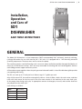
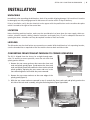
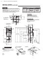
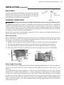
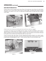
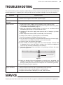
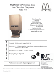
INSTRUCTION MANUAL STERO SD1 Low Temp Dishwasher MODEL: SD1 ML-130225 STERO, a division of Illinois Tool Works, Inc. 1758 Corporate Circle Petaluma, CA 94954 Phone: 800-762-7600 Fax: 707-762-5036 Website: Stero.com ST50409 (11/14) 2 | STERO SD1 LOW TEMP DISHWASHER TABLE OF CONTENTS GENERAL . . . . . . . . . . . . . . . . . . . . . . . . . . . . . . . . . . . . . . . . . . . . . . . . . . . . . . . . . . . . . . . . . . . . . . . . . . . . . . . . . . . . 3 START-UP CHECKLIST . . . . . . . . . . . . . . . . . . . . . . . . . . . . . . . . . . . . . . . . . . . . . . . . . . . . . . . . . . . . . . . . . . . . . . . . 4 INSTALLATION . . . . . . . . . . . . . . . . . . . . . . . . . . . . . . . . . . . . . . . . . . . . . . . . . . . . . . . . . . . . . . . . . . . . . . . . . . . . . . . 5 Unpacking. . . . . . . . . . . . . . . . . . . . . . . . . . . . . . . . . . . . . . . . . . . . . . . . . . . . . . . . . . . . . . . . . . . . . . . . . . . . . . . . . 5 Location. . . . . . . . . . . . . . . . . . . . . . . . . . . . . . . . . . . . . . . . . . . . . . . . . . . . . . . . . . . . . . . . . . . . . . . . . . . . . . . . . . 5 Leveling. . . . . . . . . . . . . . . . . . . . . . . . . . . . . . . . . . . . . . . . . . . . . . . . . . . . . . . . . . . . . . . . . . . . . . . . . . . . . . . . . . . 5 Converting from Straight-Through to Corner Operation. . . . . . . . . . . . . . . . . . . . . . . . . . . . . . . . . . . . . . . . . . . . 5 Installation Drawing. . . . . . . . . . . . . . . . . . . . . . . . . . . . . . . . . . . . . . . . . . . . . . . . . . . . . . . . . . . . . . . . . . . . . . . . . 6 Dish Tables . . . . . . . . . . . . . . . . . . . . . . . . . . . . . . . . . . . . . . . . . . . . . . . . . . . . . . . . . . . . . . . . . . . . . . . . . . . . . . . . 7 Plumbing Connections. . . . . . . . . . . . . . . . . . . . . . . . . . . . . . . . . . . . . . . . . . . . . . . . . . . . . . . . . . . . . . . . . . . . . . . 7 Drain Connection. . . . . . . . . . . . . . . . . . . . . . . . . . . . . . . . . . . . . . . . . . . . . . . . . . . . . . . . . . . . . . . . . . . . . . . . 7 Water Supply Connection . . . . . . . . . . . . . . . . . . . . . . . . . . . . . . . . . . . . . . . . . . . . . . . . . . . . . . . . . . . . . . . . . 7 Electrical Connection . . . . . . . . . . . . . . . . . . . . . . . . . . . . . . . . . . . . . . . . . . . . . . . . . . . . . . . . . . . . . . . . . . . . . . . . 8 Chemical Supplies. . . . . . . . . . . . . . . . . . . . . . . . . . . . . . . . . . . . . . . . . . . . . . . . . . . . . . . . . . . . . . . . . . . . . . . . . . . 8 Pump Priming. . . . . . . . . . . . . . . . . . . . . . . . . . . . . . . . . . . . . . . . . . . . . . . . . . . . . . . . . . . . . . . . . . . . . . . . . . . . . . 8 Cycle Timer Adjustment. . . . . . . . . . . . . . . . . . . . . . . . . . . . . . . . . . . . . . . . . . . . . . . . . . . . . . . . . . . . . . . . . . . . . . 9 OPERATION . . . . . . . . . . . . . . . . . . . . . . . . . . . . . . . . . . . . . . . . . . . . . . . . . . . . . . . . . . . . . . . . . . . . . . . . . . . . . . . . . 10 Controls. . . . . . . . . . . . . . . . . . . . . . . . . . . . . . . . . . . . . . . . . . . . . . . . . . . . . . . . . . . . . . . . . . . . . . . . . . . . . . . . . . 10 Machine Preparation . . . . . . . . . . . . . . . . . . . . . . . . . . . . . . . . . . . . . . . . . . . . . . . . . . . . . . . . . . . . . . . . . . . . . . . 11 Dishwashing. . . . . . . . . . . . . . . . . . . . . . . . . . . . . . . . . . . . . . . . . . . . . . . . . . . . . . . . . . . . . . . . . . . . . . . . . . . . . . 12 Draining the Dishwasher . . . . . . . . . . . . . . . . . . . . . . . . . . . . . . . . . . . . . . . . . . . . . . . . . . . . . . . . . . . . . . . . . . . . 12 CLEANING . . . . . . . . . . . . . . . . . . . . . . . . . . . . . . . . . . . . . . . . . . . . . . . . . . . . . . . . . . . . . . . . . . . . . . . . . . . . . . . . . . 13 Cleaning the Dishwasher. . . . . . . . . . . . . . . . . . . . . . . . . . . . . . . . . . . . . . . . . . . . . . . . . . . . . . . . . . . . . . . . . . . . 13 Cleaning the Wash Arms. . . . . . . . . . . . . . . . . . . . . . . . . . . . . . . . . . . . . . . . . . . . . . . . . . . . . . . . . . . . . . . . . 14 Do's and Don'ts for Your Stero Dishwasher . . . . . . . . . . . . . . . . . . . . . . . . . . . . . . . . . . . . . . . . . . . . . . . . . . . . . 14 MAINTENANCE . . . . . . . . . . . . . . . . . . . . . . . . . . . . . . . . . . . . . . . . . . . . . . . . . . . . . . . . . . . . . . . . . . . . . . . . . . . . . 14 Delime Instructions. . . . . . . . . . . . . . . . . . . . . . . . . . . . . . . . . . . . . . . . . . . . . . . . . . . . . . . . . . . . . . . . . . . . . . . . . 14 Lubrication . . . . . . . . . . . . . . . . . . . . . . . . . . . . . . . . . . . . . . . . . . . . . . . . . . . . . . . . . . . . . . . . . . . . . . . . . . . . . . . 14 TROUBLESHOOTING . . . . . . . . . . . . . . . . . . . . . . . . . . . . . . . . . . . . . . . . . . . . . . . . . . . . . . . . . . . . . . . . . . . . . . . . 15 SERVICE . . . . . . . . . . . . . . . . . . . . . . . . . . . . . . . . . . . . . . . . . . . . . . . . . . . . . . . . . . . . . . . . . . . . . . . . . . . . . . . . . . . . 15 © STERO 2014 STERO SD1 LOW TEMP DISHWASHER | Installation, Operation and Care of SD1 DISHWASHER SAVE THESE INSTRUCTIONS GENERAL The Model SD1 Dishwasher is a low temperature (140°F recommended, 120°F minimum), chemical sanitizing, rack-type dishwasher for use with accessory 20" x 20" racks. It is equipped with a 1 HP thermally p rotected (internal) pump motor. The motor must cool to restart the pump. The revolving stainless steel ball bearing wash / rinse arms above and below provide thorough distribution of water jets to all dishware surfaces. Arms are easily removable for cleaning and are interchangeable. Stainless steel tubing connects upper and lower systems. All three doors open together when the spring counter-balanced handle is raised. Durable door glides provide easy opening and closing. The SD1 can wash up to 37 racks per hour. Water usage is 1.7 gallons per rack. After initial manual fill, the machine automatically washes a rack of dishes, drains the wash water, and then refills with fresh water for the rinse cycle. The rinse water remains in the machine for the next wash cycle. At the proper time during each cycle, an appropriate amount of detergent, rinse aid, and sanitizer chemicals are pumped into the wash tank. Cycle timing is as follows: Wash 40 seconds Drain 10 seconds Flush 3 seconds Fill 9 seconds Rinse 20 seconds 3 4 | STERO SD1 LOW TEMP DISHWASHER START-UP CHECKLIST BEFORE POWER IS APPLIED ____ 1. Check all utility service connections for tightness (electric, hot water and drain(s)). ____2. Verify drain is connected with air gap (per your local code) and properly draining. ____3. Check for any loose hardware. ____4. Check door wrap to table for interference. ____5. Check free rotation of wash/rinse arms. ____6. Check to see that all strainer pans and screens are in place. AFTER POWER IS APPLIED AND WATER TURNED ON ____ 1. Verify water supply is connected properly and not leaking. ____2. Verify correct supply voltage and phase to machine and confirm with data plate ratings. ____3. Close door and allow machine to fill completely. ____4. Check wash tank to ensure 140° operating temperature after fill. RUN A 1 MINUTE CYCLE ____ 1. Check operation of door interlock switch. ____2. Check for proper pump motor operation and check for leaks. ____3. Check wash tank for proper water level during start up and operation. REINSTALL ANY PANELS REMOVED STERO SD1 LOW TEMP DISHWASHER | INSTALLATION UNPACKING Immediately after unpacking the dishwasher, check it for possible shipping damage. If this machine is found to be damaged, save the packaging material and contact the carrier within 15 days of delivery. Prior to installation, verify that the electrical service agrees with the specifications on the machine data plate which is located to the right of the control box. LOCATION Before finalizing machine location, make sure that consideration has been given for water supply, drain connection, electrical conduit, tabling, chemical containers and supply lines, as well as adequate clearance for opening the doors. A hood or vent may be required in order to meet local codes. LEVELING The dishwasher must be level before any connections are made. With the dishwasher in its operating location, turn the threaded feet as required to level the machine front-to-back and side-to-side. CONVERTING FROM STRAIGHT-THROUGH TO CORNER OPERATION The SD1 is shipped from the factory for straight-through operation. To convert to corner operation, move the rack track and splash guard as follows: 1. Remove the two screws and nuts that secure the front rack track and splash guard (Figure 1) and remove the front rack track and splash guard. Reassemble the front rack track and splash guard by replacing the two screws and nuts in the same mounting holes from which they were removed. SCREWS 2. Remove the two screws and nuts at the outer edges of the splash guard (Figure 2). FRONT RACK TRACK AND SPLASH GUARD Figure 1 3. With the two screws and nuts removed in step 2, reattach the front rack track and splash guard to the left side of the rack track assembly, using the mounting holes (Figure 3) provided. SCREWS MOUNTING HOLES Figure 2 Figure 3 5 6 | STERO SD1 LOW TEMP DISHWASHER INSTALLATION (continued) Electrical and grounding connections must comply with the applicable portions of the National Electrical Code and/or other local electrical codes. Plumbing connections must comply with applicable sanitary, safety and plumbing codes. Drain and fill line configurations vary, some methods are shown on this drawing. ELECTRICAL CONNECTION MINIMUM MAXIMUM RATED SUPPLY CIRCUIT OVERCURRENT AMPS CONDUCTOR PROTECTIVE AMPACITY DEVICE 14.0 20 20 ELEC. SPECS 120/60/1 E1 PLUMBING NOTES: WALL P2 4 1/2" MIN CLEARANCE FROM CHAMBER FOR STRAIGHT THRU OR CORNER INSTALLATION CL WATER HAMMER ARRESTOR (MEETING ASSE-1010 STANDARD OR EQUIVALENT) TO BE SUPPLIED (BY OTHERS) IN COMMON WATER SUPPLY LINE AT SERVICE CONNECTION. RECOMMENDED WATER HARDNESS TO BE 3 GRAINS OR LESS FOR BEST RESULTS. P1 13 5/8" 12 5/8" MISCELLANEOUS NOTES: WALL ALL DIMENSIONS TAKEN FROM FLOOR LINE MAY INCREASE 3/4" OR DECREASE 1/2" DEPENDING ON LEG ADJUSTMENT. NET WEIGHT OF MACHINE: 210 LBS. DOMESTIC SHIPPING WEIGHT: 235 LBS. SIZE OF RACKS - 19-3/4" X 19-3/4" 3/4 H.P. MOTOR 3/8" 10 1/8" 4 1/2" MIN CLEARANCE TO TANK WALL FOR CORNER INSTALLATION E1 2 1/2" 24 7/8" CL 22" CL CL 20 1/2" 28 3/4" OVERALL WIDTH 11" P1 75 7/16" 2 1/8" 20 3/4" 2 1/8" 70 3/4" MAX HANDLE HEIGHT 69" OVERALL HEIGHT 16 7/8" DOOR OPENING 68 5/8" 66 7/16" 62 9/16" 57 9/16" 34" 40 1/4" MIN HANDLE HEIGHT P2 12 1/2" FLOOR CL CL 7 1/2" CHEMICAL SUPPLY CONTAINER P2 26 3/16" CONNECTION INFORMATION (*AFF - ABOVE FINISHED FLOOR) 5/16-18 SST TRUSS HD SCREW 5/16-18 SST LOCKWASHER 5/16-18 SST HEX HD NUT LEGEND E1 P1 P2 ELECTRICAL CONNECTION: 1/2" CONDUIT HOLE, 66-7/16" AFF. COMMON WATER CONNECTION: 120°F WATER MIN. (RECOMMENDED 140°F); 3/4" FPT, 62-9/16" AFF. DRAIN: 2" NPT, 12-1/2" AFF 2" MAX. SUGGESTED TABLE FABRICATION 30" 30° 1-1/4" ROLL 9" MAX TANK 10-1/2" 5/8" 21" ±1/8 MODEL: SD-1 D-950292 REV. A USE SILICONE SEALER BETWEEN TABLE AND LIP OF TANK TO PREVENT LEAKAGE 1-1/4" 21-3/4" ±1/8 STERO SD1 LOW TEMP DISHWASHER | INSTALLATION (continued) DISH TABLES Dish table end should be turned down and fitted over the lip of the dishwasher tank (Figure 4). Use an NSF approved sealer between table and tank lip to prevent leaks. Fasten tables to the tank lip; truss head screws (by others) are recommended. SIDE TABLE PLUMBING CONNECTIONS SEAL TO PREVENT LEAKAGE Figure 4 Plumbing connections must comply with applicable sanitary, safety, and plumbing codes. The plumber who connects this machine is responsible for making certain that water lines are THOROUGHLY FLUSHED OUT BEFORE connecting to any manual valve or solenoid valve. This “flush-out” is necessary to remove all foreign matter, such as chips (resulting from cutting or threading of pipes), pipe joint compound from the lines, or, if soldered fittings are used, bits of solder or cuttings from the tubing. Debris, if not removed, may lodge in the valves and render them inoperative. Manual valves or solenoid valves fouled by foreign matter, and any expenses resulting from this fouling, are NOT the responsibility of the manufacturer. Drain Connection When the dishwasher is shipped from the factory, the drain pan is assembled so the drain (Figure 5) exits from the left side of the machine. If your plumbing arrangement requires the drain to exit from the right side of the machine, rotate the drain pan and strainer, as follows: 1. Remove 2 screws and nuts at the front (Figure 5) and 2 screws and nuts at the rear of the drain pan. 2. Turn drain pan and drain pan strainer 180° so the drain exits from the right side of the machine. 3. Secure drain pan by re-installing 2 screws and nuts at the front and 2 screws and nuts at the rear. A 2" NPT fitting (external thread) is provided at the drain pan for proper connection to a suitable drain. LINE STRAINER FRONT SCREWS DRAIN Figure 5 Figure 6 Water Supply Connection A water hammer arrestor (meeting ASSE-1010 Standard) should be provided (by others) in the water supply line ahead of its connection to the line strainer. Connect the water supply line to the line strainer using 3 ⁄4" pipe (Figure 6). The recommended water supply temperature is 140°F (60°C); minimum temperature is 120°F (49°C). Flowing pressure of 20 – 25 psig is recommended (15 – 25 psig is required) at the dishwasher. If the water pressure is higher than 25 psig, a pressure regulating valve with internal thermal expansion bypass must be supplied (by others) in the water supply line. For convenience when cleaning, a water tap should be installed near the machine with heavy duty hose and squeeze valve. Water must be proper hardness. Recommended hardness range is 3 grains per gallon, or less. Lower hardness promotes corrosion, higher hardness may cause excessive formation of lime scale. 7 8 | STERO SD1 LOW TEMP DISHWASHER INSTALLATION (continued) ELECTRICAL CONNECTION Electrical and grounding connections must comply with the applicable portions of the National Electrical Code and/or other local electrical codes. Disconnect electrical power supply and place a tag at the disconnect switch to indicate that you are working on the circuit. ELECTRICAL DATA Model Volts / Hertz / Phase Minimum Circuit Ampacity / Maximum Protective Device AMPS SD1 120 / 60 / 1 20 Compiled in accordance with the National Electrical Code, ANSI / NFPA 70, 1996 edition. Connect the incoming power supply through the hole for 1 ⁄ 2" trade size conduit (Figure 7) in the back of the control box. Pigtail leads on the machine contactor and a ground lead are provided. Refer to the wiring diagram located on the inside of the control box lid. CONDUIT HOLE Figure 7 PRIMING SWITCHES Figure 8 CHEMICAL SUPPLIES Place the detergent, rinse aid, and sanitizer containers (which are obtained from an independent supplier) in a location where the delivery tubes will reach them. Put the red delivery tube in the detergent container, white in the sanitizer container, and blue in the rinse aid container. Make sure the delivery tube standpipes extend to the bottom of each container. PUMP PRIMING Prior to operation, the detergent, sanitizer, and rinse aid delivery pumps must be primed. Priming switches (Figure 8) are provided on the control box. With electrical power connected, the doors closed, and the delivery tubes properly installed in each container, turn the power switch On, press the FILL switch to fill the wash tank with water, and press and hold each priming switch until the corresponding chemical reaches the end of the delivery tube. Priming is necessary only at installation and after deliming or replacing the sanitizer, rinse aid, or detergent container(s). STERO SD1 LOW TEMP DISHWASHER | INSTALLATION (continued) CYCLE TIMER ADJUSTMENT The cycle timer, which regulates the dishwasher cycle, may require adjustment in order to suit local conditions. To gain access to the cycle timer, loosen the bottom screw on the access cover located on the right side of the control box and rotate the access cover up (Figure 9). ACCESS COVER TIMER ADJUSTING WRENCH CYCLE TIMER LOOSEN SCREW Figure 9 Figure 10 The cycle timer (Figure 9) makes one complete revolution (one dishwasher cycle) in 90 seconds. It consists of seven cams, four of which can be adjusted. These cams actuate switches which control various machine functions. A degree marker is located at the right end of the timer and corresponding notches on each cam are marked off in five degree increments. Every four degrees of rotation equals one second. A description of the seven timer cams, from left to right, and each cam’s function follows: 1. The Cycle/Reset cam, which is not adjustable, controls power to the timer motor and is activated by the door cycle switch. 2. The Wash/Start cam, which is not adjustable, controls power to the wash pump motor. 3. The Drain cam, which is not adjustable, controls power to the drain valve. This cam is factory-set to open the drain at 42.5 seconds into the cycle and keep it open until 52.5 seconds into the cycle. 4. The Fill/Flush cam controls power to the fill valve. During the last three seconds of drain time, the fill valve opens to provide a fresh water flush of the wash chamber. This flush time may be increased or decreased, as required by local operating conditions, by rotating the right half of the cam. This cam is factory-set to open the fill valve to fill the wash chamber at 49.5 seconds into the cycle and keep it open until 58.5 seconds into the cycle. At 20 psig flowing pressure, the required quantity of water, 1.7 gallons, is allowed to flow into the dishwasher. If flowing pressure is different than 20 psig (or if drain flush time has been changed), the fill time will need to be increased or decreased to allow the dishwasher to operate with a minimum of 1.7 gallons of water. 5. The Detergent cam controls power to the detergent delivery pump. This cam is factory-set to turn the pump on at 1 second into the cycle and turn it off at 6.5 seconds into the cycle. This time may be increased or decreased to accommodate the type and concentration of detergent. 6. The Sanitizer cam controls power to the sanitizer delivery pump. This cam is factory-set to turn the pump on at 57 seconds into the cycle and turn it off at 60 seconds into the cycle. This time may be increased or decreased to accommodate the type and concentration of sanitizer. 7.The Rinse Aid cam controls power to the rinse aid delivery pump. This cam is factory-set to turn the pump on at 56 seconds into the cycle and turn it off at 59 seconds into the cycle. This time may be increased or decreased to accommodate the type and concentration of rinse aid. Start and stop time of each function is controlled by the size of the gap between the right and left halves of its cam and the degree of rotation at which the gap occurs. If an adjustment is required, use the supplied timer adjusting wrench (Figure 10) (shipped inside the control box). Rotate the left side of each cam to open the gap (increase “on” time) or close the gap (decrease “on” time). 9 10 | STERO SD1 LOW TEMP DISHWASHER OPERATION CAUTION: Items made of pewter, aluminum, and silver will be attacked by the sodium hypochlorite sanitizing agent (liquid bleach) used in this machine and therefore should not be washed in it. In addition to these detailed instructions, brief instructions for operation and cleaning can be found on the front of the control box. CONTROLS (Figure 11) DETERGENT PRIMING SWITCH SANITIZER PRIMING SWITCH RINSE AID PRIMING SWITCH POWER SWITCH DRAIN/FILL SWITCH CYCLE LIGHT COUNTER THERMOMETER Figure 11 The POWER switch turns the machine on and off. The DETERGENT, SANITIZER, and RINSE AID priming switches are used to prime the delivery pumps. To prime the pumps, press and hold each priming switch until the corresponding chemical reaches the end of the delivery tube. The DRAIN/FILL switch, when pressed and held on FILL, opens the fill valve and allows water to flow into the dishwasher. The fill valve will remain open as long as the switch is pressed. The DRAIN/FILL switch, when pressed and held on DRAIN, opens the drain valve and allows water to drain out of the dishwasher. The drain valve will remain open as long as the switch is pressed. The CYCLE LIGHT indicates when a washing cycle is in progress. The THERMOMETER indicates water temperature in the dishwasher sump. The COUNTER indicates the number of cycles that have been run. STERO SD1 LOW TEMP DISHWASHER | 11 OPERATION (continued) MACHINE PREPARATION Check to make sure that the pump intake strainer (Figure 12), the drain pan strainer (Figure 13), and the drain tube (Figure 17) are in place and that both strainers are free of debris. The pump intake strainer must drop completely to the bottom of the sump. THE DRAIN AND STRAINERS MUST BE CLEAN AND FREE OF DEBRIS AT ALL TIMES. PUMP INTAKE STRAINER DRAIN PAN STRAINER Figure 12 Figure 13 Check the wash arms to make sure that they spin freely and that no nozzles are clogged. To initially fill the machine, press the POWER switch On and press and hold the DRAIN/FILL switch on Fill for approximately ten seconds. Water level should be at the bottom of the ring on the drain tube (1.7 gallons) (Figure 14). (Water to the top of the ring would be 1.9 gallons, and to the bottom of the overflow hole would be 2.3 gallons.) The overflow hole will automatically drain any excess water. Check the chemical sight tubes (Figure 15) before beginning dishwashing. Replenish any chemical supply containers that need to be replenished. If any chemical has been replenished, its delivery pump must be primed by pressing the corresponding prime switch — until the chemical reaches the end of the delivery tube. OVERFLOW HOLE WATER LEVEL (1.7 GALLONS) CHEMICAL SIGHT TUBES Figure 14 Figure 15 12 | STERO SD1 LOW TEMP DISHWASHER OPERATION (continued) DISHWASHING Scrape and/or rinse dishes to remove food particles and other debris. Never use steel wool on ware to be loaded into the dishwasher. Place the dishes in a rack. Do not stack dishes on top of each other as water must have free access to all sides of every dish. Stand plates edgewise in a peg-type rack (Figure 16). Place cups, glasses and bowls upside down in an open or compartment-type rack (Figure 16). Silverware and other small pieces should lay loosely on the bottom of an open-type rack. Do not allow foreign objects to enter the unit, especially metallic contaminants. Figure 16 Open doors, slide the rack of dishes into the dishwasher, close the doors, and begin rinsing and loading another rack of dishes. When the doors are closed, the dishwasher cycle will begin automatically. After 90 seconds, the CYCLE LIGHT goes out to indicate that the cycle has been completed, the doors may be raised, and the rack of dishes can be removed. Slide the next rack of dishes into the dishwasher, close the doors and continue operation. If the washing cycle is interrupted, the cycle will continue from the time of interruption and complete the cycle. None of the machine functions will operate unless the POWER switch is on and the doors are closed. Occasionally, check the drain pan strainer (Figure 13) and clean it as necessary to prevent it from becoming clogged (which could result in water splashing onto the floor). DO NOT remove the drain pan strainer during a wash cycle. Whenever there is an extended period of time between racks, check the thermometer before washing the next rack of dishes. If the water temperature is below 120°F, the machine must be manually drained and manually refilled with fresh water. DRAINING THE DISHWASHER The machine may be drained by either pressing and holding the DRAIN/FILL switch on DRAIN until the machine is completely drained, or by opening the doors and removing the drain tube (the drain stopper is attached to the bottom of the drain tube) (Figure 17). When the machine is completely drained, replace the drain tube/drain stopper, close the doors and hold the DRAIN/FILL switch on FILL for approximately ten seconds. DRAIN TUBE DRAIN STOPPER Drain and clean the machine at the end of each working shift. Figure 17 STERO SD1 LOW TEMP DISHWASHER | 13 CLEANING CLEANING THE DISHWASHER Clean the dishwasher after each working shift. Never use steel wool to clean warewasher surfaces. Use only products formulated to be safe on stainless steel. 1. Drain machine. Turn the POWER switch Off. 2. Thoroughly cleanse and flush the dishwasher interior and then drain any water that may have accumulated. Wipe down the exterior of the machine. Remove remaining soil with a soft cloth or brush and mild cleanser. Rinse again. Do not allow food soil to accumulate on the tank bottom. Figure 18 3. Remove the pump intake strainer (Figure 12), the drain tube/drain stopper (Figure 17), and the drain pan strainer (Figure 13) and scrub them in a sink. 4. Check the wash arms to make sure they spin freely and that no nozzles are clogged. If any obstructions are present, refer to Cleaning the Wash Arms, below. 5. Replace any components that were removed for cleaning. Make sure drain pan strainer is replaced with the strainer screen down and the handles at the front and back facing up (Figure 18). 6. To continue washing, turn the POWER switch On, close the doors, and press and hold the DRAIN/FILL switch on FILL for 10 seconds. 7. After cleaning at end-of-day, leave doors open and allow the interior to air out and dry. Cleaning the Wash Arms If the wash arms do not spin freely or if the nozzles contain lime deposits or other forms of debris, they need to be thoroughly cleaned, as follows: 1. Unscrew the knurled disks and remove the upper and lower wash / rinse arms (Figure 19). Be careful not to drop the wash / rinse arms during removal, particularly the upper arm. 2. Use a straightened paper clip or a toothpick to poke any nozzle obstructions back into the wash arm. 3. Unscrew the threaded end caps (Figure 20) and thoroughly clean and flush the wash arms in a sink. Replace the end caps. 4. Replace the arms. Rotate the knurled disks to screw in the hub of the upper and lower wash / rinse arms until secure but do not overtighten. The upper and lower wash / rinse arms are interchangeable. END CAP Figure 19 Figure 20 14 | STERO SD1 LOW TEMP DISHWASHER CLEANING (continued) DO’S AND DON’TS FOR YOUR NEW STERO DISHWASHER DO assure proper water hardness. DO pre-scrap dishes thoroughly. DO use only detergents recommended by your chemical professional. DO at the end of the day, thoroughly cleanse the machine, rinse, and dry (leave door open). DO closely follow your chemical professional’s prescribed deliming schedule. DO use only products formulated to be safe on stainless steel. DO NOT use detergents formulated for residential dishwashers. DO NOT allow food soil to accumulate on the tank bottom. DO NOT exceed chemical manufacturer’s recommended concentrations for detergent, sanitizer, rinse aid, or lime scale remover. DO NOT use steel wool to clean ware or warewasher surface. DO NOT allow foreign objects to enter the unit, especially metallic contaminants. NOTE: Failure to follow use, care and maintenance instructions may void your Stero warewasher warranty. MAINTENANCE DELIME INSTRUCTIONS Check with your chemical provider for deliming procedures. LUBRICATION The motor has sealed ball bearings and therefore requires no lubrication. STERO SD1 LOW TEMP DISHWASHER | 15 TROUBLESHOOTING This section outlines various symptoms and possible causes that may be encountered in the event of abnormal machine operation. If symptoms persist after possible causes have been checked, service may be required. Symptom Possible Causes No machine operation. 1.Machine POWER switch in the OFF position. 2. Blown fuse or tripped circuit breaker at power supply. Continuous machine operation. 1. Problem with timer. Contact your local service provider. Dishes not clean. 1. Pump intake strainer clogged causing inadequate water supply to pump. 2. Obstruction in wash arm nozzles or bearings preventing arms from turning. Refer to CLEANING THE DISHWASHER, page 13. 3. Wash arms improperly assembled. Make sure end caps are assembled and the knurled disks on the wash / rinse arm hubs are secure. 4. Inadequate fill due to low supply water pressure and / or improper cycle timer adjustment. 5. Water temperature too low (140°F recommended, 120°F minimum). 6. Improper water hardness (3 grains/gallon is recommended). 7. Excessive lime deposits throughout wash/rinse system. 8. Dirty line strainer (see Figure 6) causing reduced water flow. Turn off water supply, remove strainer cap, withdraw and clean screen, and reassemble. 9. Incorrect type or concentration of detergent. 10. Check to make sure chemical supply hoses are in the their proper container: Red in detergent, blue in rinse aid, white in sanitizer. Also, check the standpipes to make sure they extend to the bottom of the container. 11. Wash tube disconnected from manifold or O-ring leaking, resulting in low water pressure to upper arm. WASH ARM BEARING Figure 21 12. Wash arm bearings (Figure 21) damaged or excessively worn, preventing free rotation of the wash arm. To change the wash arm bearing assembly, unscrew bearing assembly from wash/rinse arm and replace with a new bearing assembly. 13. Check for empty chemical containers. Spotting of silverware, glasses and dishes. 1. Improperly loaded racks. 2. Water temperature too low (140°F recommended, 120°F minimum). 3. Improper water hardness (3 grains/gallon is recommended). 4. Improper concentration of detergent, rinse aid, and/or sanitizer. SERVICE Contact your local Stero-authorized service office for any repairs or adjustments needed on this equipment. 16 | STERO SD1 LOW TEMP DISHWASHER ST50409 (11/14)