1
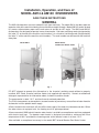
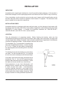
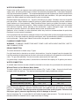
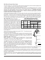
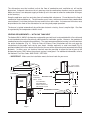
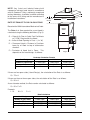
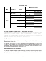
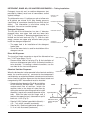
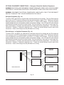
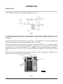
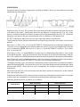
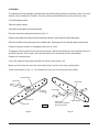
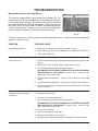
MODEL AM14 & AM14C DISHWASHERS
MODELS
AM14
AM14C
ML-110976
ML-110977
701 S. RIDGE AVENUE
TROY, OHIO 45374-0001
937 332-3000
www.hobartcorp.com
FORM 34554 (Dec. 2000)
POST IN A PROMINENT LOCATION THE INSTRUCTIONS TO BE FOLLOWED IN THE
EVENT THE SMELL OF GAS IS DETECTED. THIS INFORMATION CAN BE OBTAINED
FROM THE LOCAL GAS SUPPLIER.
IMPORTANT
IN THE EVENT A GAS ODOR IS DETECTED, SHUT
DOWN UNIT(S) AT MAIN SHUTOFF VALVE AND
CONTACT THE LOCAL GAS COMPANY OR GAS
SUPPLIER FOR SERVICE.
FOR YOUR SAFETY
DO NOT STORE OR USE GASOLINE OR OTHER
FLAMMABLE VAPORS OR LIQUIDS IN THE
VICINITY OF THIS OR ANY OTHER APPLIANCE.
© HOBART CORPORATION 1982, 1995
–2–
TABLE OF CONTENTS
GENERAL . . . . . . . . . . . . . . . . . . . . . . . . . . . . . . . . . . . . . . . . . . . . . . . . . . . . . . . . . . . . . . . . . . 4
INSTALLATION . . . . . . . . . . . . . . . . . . . . . . . . . . . . . . . . . . . . . . . . . . . . . . . . . . . . . . . . . . . . . . 5
UNPACKING . . . . . . . . . . . . . . . . . . . . . . . . . . . . . . . . . . . . . . . . . . . . . . . . . . . . . . . . . . . . . . 5
INSTALLATION CODES . . . . . . . . . . . . . . . . . . . . . . . . . . . . . . . . . . . . . . . . . . . . . . . . . . . . . 5
LOCATION . . . . . . . . . . . . . . . . . . . . . . . . . . . . . . . . . . . . . . . . . . . . . . . . . . . . . . . . . . . . . . . 5
WATER REQUIREMENTS . . . . . . . . . . . . . . . . . . . . . . . . . . . . . . . . . . . . . . . . . . . . . . . . . . . 6
PLUMBING CONNECTIONS . . . . . . . . . . . . . . . . . . . . . . . . . . . . . . . . . . . . . . . . . . . . . . . . . 6
DRAIN CONNECTION . . . . . . . . . . . . . . . . . . . . . . . . . . . . . . . . . . . . . . . . . . . . . . . . . 6
WATER CONNECTION . . . . . . . . . . . . . . . . . . . . . . . . . . . . . . . . . . . . . . . . . . . . . . . . . . 6
Without Electric or Gas Booster Water Heater . . . . . . . . . . . . . . . . . . . . . . . . . . . . 6
With Electric Booster Water Heater . . . . . . . . . . . . . . . . . . . . . . . . . . . . . . . . . . . . . 7
GAS TANK HEAT . . . . . . . . . . . . . . . . . . . . . . . . . . . . . . . . . . . . . . . . . . . . . . . . . . . . . . 7
VENTING REQUIREMENTS — WITH GAS TANK HEAT . . . . . . . . . . . . . . . . . . . . . . 8
RATE OF EXHAUST FLOW CALCULATIONS . . . . . . . . . . . . . . . . . . . . . . . . . . . . . . . 9
ELECTRICAL CONNECTIONS . . . . . . . . . . . . . . . . . . . . . . . . . . . . . . . . . . . . . . . . . . . . . . 10
Dishwasher . . . . . . . . . . . . . . . . . . . . . . . . . . . . . . . . . . . . . . . . . . . . . . . . . . . . . . . . . . 10
Check Rotation (Three Phase Machines Only) . . . . . . . . . . . . . . . . . . . . . . . . . . . 10
Electric Booster Water Heater . . . . . . . . . . . . . . . . . . . . . . . . . . . . . . . . . . . . . . . . . . . 10
OPTIONAL EQUIPMENT CONNECTIONS – Vent Fan & Gas Booster . . . . . . . . . . . . . . 11
Vent Fan Control . . . . . . . . . . . . . . . . . . . . . . . . . . . . . . . . . . . . . . . . . . . . . . . . . . . 11
Hobart Infrared Booster Gas Water Heater . . . . . . . . . . . . . . . . . . . . . . . . . . . . . . 11
DETERGENT, RINSE AID, OR SANITIZER DISPENSERS – Tubing Installation . . . . . . 12
Detergent Dispenser . . . . . . . . . . . . . . . . . . . . . . . . . . . . . . . . . . . . . . . . . . . . . . . . 12
Rinse Aid Dispenser . . . . . . . . . . . . . . . . . . . . . . . . . . . . . . . . . . . . . . . . . . . . . . . . 12
Chemical Sanitizer Dispenser . . . . . . . . . . . . . . . . . . . . . . . . . . . . . . . . . . . . . . . . . 12
OPTIONAL EQUIPMENT CONNECTIONS – Detergent, Rinse Aid, Sanitizer Dispenser 13
Detergent Dispenser . . . . . . . . . . . . . . . . . . . . . . . . . . . . . . . . . . . . . . . . . . . . . . . . 13
Rinse Aid and / or Sanitizer Dispenser . . . . . . . . . . . . . . . . . . . . . . . . . . . . . . . . . 13
OPERATION . . . . . . . . . . . . . . . . . . . . . . . . . . . . . . . . . . . . . . . . . . . . . . . . . . . . . . . . . . . . . . 14
PREPARATION . . . . . . . . . . . . . . . . . . . . . . . . . . . . . . . . . . . . . . . . . . . . . . . . . . . . . . . . . . .
DISHWASHING . . . . . . . . . . . . . . . . . . . . . . . . . . . . . . . . . . . . . . . . . . . . . . . . . . . . . . . . . . .
CLEANING . . . . . . . . . . . . . . . . . . . . . . . . . . . . . . . . . . . . . . . . . . . . . . . . . . . . . . . . . . . . . .
DOs AND DON’Ts FOR YOUR NEW HOBART WAREWASHER . . . . . . . . . . . . . . .
14
15
16
17
MAINTENANCE. . . . . . . . . . . . . . . . . . . . . . . . . . . . . . . . . . . . . . . . . . . . . . . . . . . . . . . . . . . . . 18
Wash Arms . . . . . . . . . . . . . . . . . . . . . . . . . . . . . . . . . . . . . . . . . . . . . . . . . . . . . . . 18
Motor(s) . . . . . . . . . . . . . . . . . . . . . . . . . . . . . . . . . . . . . . . . . . . . . . . . . . . . . . . . . . 18
Gas Flue . . . . . . . . . . . . . . . . . . . . . . . . . . . . . . . . . . . . . . . . . . . . . . . . . . . . . . . . . . 18
TROUBLESHOOTING . . . . . . . . . . . . . . . . . . . . . . . . . . . . . . . . . . . . . . . . . . . . . . . . . . . . . . . 19
Manual Reset Button on Pump Motors . . . . . . . . . . . . . . . . . . . . . . . . . . . . . . . . . . 19
SERVICE . . . . . . . . . . . . . . . . . . . . . . . . . . . . . . . . . . . . . . . . . . . . . . . . . . . . . . . . . . . . . . . 20
–3–
Installation, Operation, and Care of
MODEL AM14 & AM14C DISHWASHERS
SAVE THESE INSTRUCTIONS
GENERAL
The AM14 dishwashers are semi-automatic rack-type machines. On model AM14, the doors open on
opposite sides of the machine allowing the rack to move straight through. Model AM14C can be located
in a corner; adjacent doors open so the rack moves in and out at a 90° angle. The AM14 and AM14C
dishwashers are designed to operate in one of two modes: Hot water sanitizing mode (designated by
the letter "H" at the end of the machine serial number), or a chemical sanitizing mode (designated by
the letter "L" at the end of the machine serial number). The serial number can be found on the machine
data plate.
Model AM14
Model AM14C
with Booster Heater shown
Fig. 1
DO NOT attempt to operate this dishwasher in the chemical sanitizing mode without a properly
installed, NSF-listed, chemical sanitizer feeder (not supplied with machine). Contact an authorized
detergent representative for information about a chemical sanitizer feeder.
The pump motor is rated 1 H.P. and has thermal overload protection.
The fill line incorporates an atmospheric vacuum breaker to prevent any reverse flow of water from the
dishwasher into the potable water supply.
A float, located in the wash tank, will shut off the heat supply if the water level becomes too low. When
the water returns to a proper level, the heating circuit is again operational.
A frame-mounted 13KW electric booster water heater is available as an option on machines equipped
with electric tank heat. The booster water heater is designed to maintain a minimum final rinse
temperature of 180°F provided the incoming water to the booster heater is at least 110°F.
Also available as an optional accessory is the model IB57 Infrared Booster Gas Water Heater.
–4–
INSTALLATION
UNPACKING
Immediately after unpacking the dishwasher, check for possible shipping damage. If this machine is
found to be damaged, save the packaging material and contact the carrier within 15 days of delivery.
Prior to installation, test the electrical service to make sure it agrees with the specifications on the
machine data plate which includes the optional electric booster, if equipped. The dishwasher data
plate is located on the side of the control box.
INSTALLATION CODES
Installation must be in accordance with state and local codes, or in the absence of local codes, with
the National Fuel Gas Code, ANSI Z223.1 (latest edition) if applicable, and the National Electrical Code
ANSI/NFPA 70 (latest edition). In Canada, the installation standards are: CAN/CGA B149.1,
CAN/CGA B149.2, and CSA C22.2 No.1 (latest editions).
LOCATION
Place the dishwasher in its operating location. Before finalizing the location, make sure that
consideration has been given for the electrical conduit, water supply, drain connection, gas supply and
venting (if applicable), tabling (if needed), chemical feeder replenishment (if applicable), and adequate
clearance for opening the doors. Allow adequate clearance for service.
The control box (Fig. 1) is mounted 45/8" below the dish
table when shipped from the factory. It can be changed
to 111/8" or 5/8" below the dish table by removing the
two mounting bolts and reinstalling them in the holes
provided.
The dishwasher must be level before any connections
are made. Turn the threaded feet (Fig. 1) as required
to level the machine and adjust to the desired height.
Dish tables should be turned down and fitted into the
dishwasher (Fig. 2). Use an NSF approved sealer
between table and tank lip to prevent leakage. Fasten
the tables to the tank lip with truss head screws.
High-temperature or gas heat dishwashers will
probably require a hood or vent over the dishwasher
in order to meet local codes. Low-temperature
chemical sanitizing machines or low usage electric
heat dishwashers may not require individual venting
of the machine if the room is amply exhausted. Refer
to pages 8 and 9 for venting and hood requirements.
–5–
Fig. 2
WATER REQUIREMENTS
Proper water quality can improve ware washing performance by reducing spotting, lowering chemical
supply costs, enhancing effectiveness of labor, and extending equipment life. Local water conditions
vary from one location to another. The recommended proper water treatment for effective and efficient
use of this equipment will also vary depending on the local water conditions. Ask your municipal water
supplier for details about local water specifics prior to installation.
Recommended water hardness is 4 – 6 grains of hardness per gallon. Chlorides must not exceed 50
parts per million. Water hardness above 6 grains per gallon should be treated by a water conditioner
(water softener or in-line treatment). Water hardness below 4 grains per gallon also requires a water
treatment to reduce potential corrosion. Water treatment has been shown to reduce costs associated
with machine cleaning, reduce deliming of the dishwasher, reduce detergent usage, and reduce
corrosion of metallic surfaces in the booster water heater and dishwasher.
Sediment, silica, chlorides, or other dissolved solids may lead to a recommendation for particulate
filtration or reverse osmosis treatment.
If an inspection of the dishwasher or booster heater reveals lime build-up after the equipment has been
in service, in-line water treatment should be considered, and, if recommended, should be installed and
used as directed. Contact your Hobart Service office for specific recommendations.
PLUMBING CONNECTIONS
WARNING: PLUMBING CONNECTIONS MUST COMPLY WITH APPLICABLE SANITARY, SAFETY,
AND PLUMBING CODES.
DRAIN CONNECTION
The drain connection is made using 2" pipe.
If a right hand drain is desired on an electric heat machine, it can be changed from the standard lefthand by removing the pipe plug from the drain valve and reinstalling it in the opposite end of the drain
valve. On gas heat machines, the drain must be connected on the right side.
If a grease trap is required by code, it should have a minimum flow capacity of 42 gallons per minute.
WATER CONNECTION
A suitable water hammer arrestor should be installed in the water line just ahead of the dishwasher.
Without Electric or Gas Booster Water Heater
The water supply line is connected to the line strainer (Fig. 1) with 3/4" pipe. A manual shut off valve
and pipe union are required. The required incoming water supply temperature follows:
Sanitizing Mode
Fill and Final Rinse — Water Supply
Minimum Temperature
Recommended Temperature
Hot Water Sanitizing
180°F
(82°C)
180°F
(82°C)
Chemical Sanitizing (Normal Duty)
120°F
(49°C)
140°F
(60°C)
Chemical Sanitizing (Light Duty)
120°F
(49°C)
140°F
(60°C)
Proper dishwasher operation requires a flowing pressure of 20 ± 5 psig at the dishwasher. If the flowing
pressure exceeds 25 psig, a pressure reducing valve (not supplied) must be installed in the water
supply line. CAUTION: The water pressure regulator must have a relief by-pass. Failure to use
the proper type of pressure regulator may result in damage to the unit.
A pressure gauge (Fig. 1) is provided for verification of proper water pressure. The water pressure is
monitored when the solenoid valve is open and water is flowing.
–6–
With Electric Booster Water Heater
The water supply line is connected to the flow control ahead of the line strainer below the booster with
3
/4" pipe. A manual shut off valve and pipe union are required.
The water supply should have a minimum temperature of 110°F, and a flowing pressure of 15 – 25 psig
at the pressure gauge on top of the machine. If the flowing pressure exceeds 25 psig, a pressure
reducing valve (not supplied) must be installed in the water supply line. CAUTION: The water
pressure regulator must have a relief by-pass. Failure to use the proper type of pressure
regulator may result in damage to the unit.
Incoming water temperature below 110°F may require the wash cycle time to be extended from 40 to
60 seconds. To have the cycle time adjusted, contact your local authorized Hobart Service Office.
When the fill / final rinse valve is on, water from the booster tank enters the dishwasher through the
final rinse arms. During the rinse cycle, this water is 180°F. Water will likely dribble out of the lower
rinse arm into the tank between cycles due to the natural expansion of water as it is being heated.
GAS TANK HEAT (When Specified)
GAS PRESSURE SPECIFICATION
[ FLOWING GAS PRESSURE — NOT STATIC ]
Check the gas data plate attached to the
Inches W.C. (Water Column)
dishwasher or the tag attached to the incoming
Type
gas piping for the type of gas to be used. Model
of
BTU/HR Incoming Line Pressure Manifold
Connect the gas supply to the 1/2" NPT gas
Gas
Pressure
Minimum
Maximum
inlet at the manual gas valve. The burner is
not adjustable. The maximum flowing inlet
Natural 20,000
4.5
10.5
3.2
gas pressure must not exceed the Maximum AM14
value in the table. If line pressure exceeds AM14C Propane 20,000
9.0
13.0
9.0
the Maximum value in the table, an additional
regulator valve (not supplied) must be installed
in the supply line.
Static inlet line pressure should not exceed 14" W.C. The minimum value is
for purpose of input adjustment.
The gas valve (Fig. 3) is provided with a pressure tap to measure the gas
pressure downstream, which is also the manifold pressure. Gas supply piping
must have a sediment trap (supplied by others) installed ahead of the
dishwasher's gas control (Fig. 3).
Gas Valve
Manual Valve
NOTE: DO NOT use Teflon tape on gas line pipe threads. For gas line pipe
connections, use LOCTITE 565, Hobart part 546292, or a flexible sealant
suitable for use with Natural and Propane Gases.
The appliance and its gas connections must be leak tested before placing the
appliance in operation. Use soapy water for leak test. DO NOT use open
flame. The installation must conform with local codes, or in the absence of
local codes, with the National Fuel Gas Code, ANSI Z223.1 (latest edition).
Copies may be obtained from American Gas Association, Inc., 1515 Wilson
Boulevard, Arlington, VA 22209.
By Others
Sediment Trap
PL-53347
Fig. 3
The appliance and its individual shutoff valve must be disconnected from the gas supply piping system
during any pressure testing of that system at test pressures in excess of 1/2 psig (3.45kPa).
The appliance must be isolated from the gas supply piping system by closing its individual manual
shutoff valve during any pressure testing of the gas supply piping system at test pressures equal to or
less than 1/2 psig (3.45kPa).
Dissipate test pressure from the gas supply line before re-connecting the appliance and its manual
shutoff valve to the gas supply line. Caution: Failure to follow this procedure may damage the gas
valve.
–7–
The dishwasher must be installed so that the flow of combustion and ventilation air will not be
obstructed. Adequate clearances for air openings into the combustion chamber must be provided.
Make sure there is an adequate supply of make-up air in the room to allow for combustion of the gas
at the burner(s).
Keep the appliance area free and clear from all combustible substances. Do not obstruct the flow of
combustion and ventilation air. The dishwasher must have a minimum clearance from combustible
construction of 1 inch from the flue at the rear and 0 inches at the sides. A clearance of 40 inches must
be provided at the front of the dishwasher for servicing and proper operation.
The burner is ignited automatically by solid state electronic circuitry; there is no pilot light. Gas flow
is regulated by the temperature control circuit.
VENTING REQUIREMENTS — WITH GAS TANK HEAT
The Hobart AM14 / AM14C dishwasher equipped for gas tank heat is not provided with a flue collar and
is not intended to have the flue directly connected to a ventilation system. However, the products of
combustion must be vented to the outside air. The most common method of venting is a vent hood over
the entire dishwasher (Fig. 4). Refer to Rate of Exhaust Flow Calculations on the next page for
calculations of the proper vent rate for your hood. Another method is a small vent hood (Fig. 5)
positioned about five inches above the flue exit at the rear of the dishwasher and connected to existing
ductwork. In either case, an electrical interlock must be provided to allow the flow of gas to the
dishwasher burner ONLY when the exhaust system is energized. For additional information, refer to
the National Fuel Gas Code, ANSI Z223.1, NFPA 54.
• IMPORTANT: Make sure the installation meets the local code for your area.
➤
3 1 /2"
➤
➤
➤
18" OVERHANG
RECOMMENDED
OVER LOADING OR
UNLOADING DOORS
4"
➤
➤
6"
MINIMUM
MINI VENT HOOD
OVERHANG
ON ALL SIDES
➤
➤
➤
➤
➤
➤
➤
➤
1' TO 4'
CLEARANCE
3" x 3" DUCT INTO
CURRENT SYSTEM
6"
➤
5" GAP
MINIMUM
DISHWASHER FLUE EXIT
Fig. 4
Fig. 5
–8–
➤
➤
➤
➤
LENGTH
➤
RATE OF EXHAUST FLOW CALCULATIONS
➤
CLEARANCE
HEIGHT
➤
NOTE: Any listed and labeled factory-built
commercial exhaust hood tested in accordance
with UL Standard 710 by a nationally recognized
testing laboratory, should be installed according
to the terms of its listing and the manufacturer's
installation instructions.
Based on the 1996 International Mechanical Code.
The Rate of air flow required for a vent hood is
calculated using the following definitions (Fig. 6):
Q = Rate of Air Flow in Cubic Feet Per Minute
or [ CFM ] Required for the Hood.
A = Area of Hood Opening in Feet2 = (L x W)
D = Clearance Height = Distance in Feet from
lower lip of hood to top of dishwasher
chamber.
P = Perimeter of Hood that is Open. This
depends on the hood design, as follows:
Fig. 6
Perimeter Calculation Formula
Hood Design
Corner
Wall
Island
Number of Open Sides
2 Sides Open
3 Sides Open
4 Sides Open
P=
L+W
L+W+W
L+L+W+W
Dimensions
Feet
Feet
Feet
If there are four open sides (Island Design), the calculation of the Rate is as follows:
Q = 75 x A
If there are three or fewer open sides, the calculation of the Rate is as follows:
Q = 50 x A
As an alternate method, the Rate can be calculated as follows:
Q = 50 x P x D
Example:
L=3
W=3
D=2
Rate Calculations
Hood Design
Corner
Wall
Island
Number of Open Sides
2 Sides Open
3 Sides Open
4 Sides Open
Q = 75 x A
Q = 50 x A
Q = 50 x P x D
450 CFM
600 CFM
450 CFM
900 CFM
675 CFM
–9–
1200 CFM
TH
WID
➤
ELECTRICAL CONNECTIONS
WARNING: ELECTRICAL AND GROUNDING CONNECTIONS MUST COMPLY WITH THE APPLICABLE
PORTIONS OF THE NATIONAL ELECTRICAL CODE AND/OR OTHER LOCAL ELECTRICAL CODES.
WARNING: DISCONNECT ELECTRICAL POWER SUPPLY AND PLACE A TAG AT THE DISCONNECT
SWITCH TO INDICATE THAT YOU ARE WORKING ON THE CIRCUIT.
Dishwasher
Refer to the wiring diagram attached inside the control box and to the machine data plate for service
size requirements when connecting the dishwasher. Also, refer to Electrical Data, page 12.
The dishwasher electrical service connection can be made through the 11/8" diameter hole for 3/4 inch
trade size conduit located at the bottom of the right side of the control box. By removing a knockout,
this hole can be enlarged to 13/4" diameter for 1 inch trade size conduit.
A fused disconnect switch or circuit breaker (not supplied) must be installed in the electrical service
line supplying this dishwasher and should meet the requirements of your local electrical code.
All power supply connections are made at the terminal block 1TB in the control box. The machine must
be grounded according to electrical code(s); a grounding lug is provided in the control box.
Check Rotation (Three-Phase Machines Only)
Three-phase motors must rotate in the direction of the arrow on the pump housing. In order to check
rotation, observe the motor fan through the end bell. Close the machine doors and press the power
switch to ON. When the machine is completely filled, place the cycle switch (located on the side of the
control box) on MANUAL and place the WASH / RINSE switch (located under the cycle switch) on
WASH. The motor fan must rotate in the direction of the arrow on the pump housing.
If the rotation is incorrect, DISCONNECT ELECTRICAL POWER SUPPLY and interchange any two
of the incoming power supply leads. Reconnect the power supply and verify correct rotation.
Electric Booster Water Heater
The Electric Booster electrical connection is separate from the dishwasher electrical connection.
Refer to Electrical Data, page 11. Before making electrical connection, test the electrical service to
assure that it agrees with the specifications on the Electric Booster portion of the data plate. Also, refer
to the wiring diagram attached inside the cover of the control box.
A fused disconnect switch or circuit breaker must be installed in the electrical service line supplying
this booster and should meet the requirements of your local electrical code.
The electric booster service connection is made through the 13/4" hole for 1 inch trade size conduit
located at the bottom of the control box. If the booster is three phase, the electrical connection is made
to the contactor 3CON in the control box. If the booster is single phase, the electrical connection is
made to the terminal block 4TB in the control box. The machine must be grounded according to
electrical code(s); a grounding lug is provided in the control box.
– 10 –
ELECTRICAL DATA
Model
Volts / Hz / Ph
Tank Heat
Minimum Circuit Ampacity
Maximum Protective Device
AMPS
Dishwasher ONLY
Electric
50
Gas
15
Optional 13 KW
Electric Booster ONLY
208 - 240 / 60 / 1
208 / 60 / 1
Electric
80
240 / 60 / 1
Electric
80
AM14
Electric
30
Gas
15
208 - 240 / 60 / 3
AM14C
208 / 60 / 3
Electric
50
240 / 60 / 3
Electric
50
Electric
15
Gas
15
25
480 / 60 / 3
Compiled in accordance with the national electrical code, ANSI / NFPA 70 (latest edition).
OPTIONAL EQUIPMENT CONNECTIONS — Vent Fan and Gas Booster
WARNING: ELECTRICAL AND GROUNDING CONNECTIONS MUST COMPLY WITH THE APPLICABLE
PORTIONS OF THE NATIONAL ELECTRICAL CODE AND/OR OTHER LOCAL ELECTRICAL CODES.
WARNING: DISCONNECT ELECTRICAL POWER SUPPLY AND PLACE A TAG AT THE DISCONNECT
SWITCH TO INDICATE THAT YOU ARE WORKING ON THE CIRCUIT.
Vent Fan Control
The vent fan control feature is standard on machines with gas heat; it is a field installable accessory
on machines with electric heat.
The maximum switching rating for a vent fan control relay connected to terminals VFC1 and VFC2 is
1.5 Amps. The vent fan control relay provides switch contacts only and does not provide power to the
vent fan motor. When the dishwasher is connected to the vent fan, the vent fan is switched on when
the dishwasher is on, and off when the dishwasher is off.
Hobart Infrared Booster Gas Water Heater
The maximum rating for connecting a Hobart Model IB57 Dishwasher Activated infrared gas booster
water heater to BSTR1 and BSTR2 is 0.5 Amp at 24 Volts. If a Stand Alone Booster Heater is used,
no electrical connection to the dishwasher is allowed. Refer to the Infrared Booster Gas Water Heater
Manual for additional installation details.
– 11 –
DETERGENT, RINSE AID, OR SANITIZER DISPENSERS — Tubing Installation
Detergent, rinse aid, and / or sanitizer dispensers (not
provided by Hobart) must have all connections sealed
against leakage.
The dishwasher uses 1.2 gallons per rack at a flow rate
of 8 gallons per minute at 20 psig flowing pressure
(equivalent to a maximum head pressure of 46 feet of
water). This information is used when setting the
detergent, rinse aid, or sanitizer pumps.
Detergent Dispenser
REMOVE PLUGS
TO INSTALL –
DETERGENT FEEDER TUBE
DETERGENT SENSOR
The left side of the dishwasher has two 7/8" diameter
plugged holes, one upper hole and one lower hole
(Fig. 7). An alternate 7/8" diameter plugged lower hole, is
located on the front tank wall (Fig. 7). With the tank
empty, remove one upper plug and one lower plug to
install the detergent dispenser.
• The upper hole is for installation of the detergent
feeder tube.
• One of the lower holes is used for installation of the
detergent sensor.
ALTERNATE
DETERGENT SENSOR
PL-41512-1
Fig. 7
Rinse Aid Dispenser
The rinse line flange connector on top of the dishwasher has
two 1/8" NPT pipe plugs (Fig. 8).
• Remove either front or rear plug (Fig. 8) for installation of
the rinse aid dispenser tube unless a chemical sanitizer is
to be installed. If installing a chemical sanitizer, use the
rear hole for the rinse aid dispenser.
REAR PIPE PLUG
Chemical Sanitizer Dispenser
When the dishwasher is to be operated in the chemical sanitizing
mode, the machine must be converted to low-temperature
sanitization by an authorized Hobart-trained service technician
and a chemical sanitizer dispenser that has been tested and
recognized by NSF International must be installed.
• Remove the front pipe plug (Fig. 8) for installation
of the chemical sanitizer tube. To assure an
unobstructed flow of sanitizer, locate the
sanitizer tube in the denter of water flow by
drilling the sanitizer tube fitting so that its inside
diameter is equal to the outside diameter of the
tube. Slide the tube into the flange until it
touches the opposite (rear) side and then pull it
back out 1/2 inch (Fig. 9).
• Rate for 5.25% Sodium hypochlorite (bleach) —
4.5 – 7 ml. with 9 seconds (maximum).
• Rate for 8.4% Sodium hypochlorite (bleach) —
3 – 4 ml. with 9 seconds (maximum).
– 12 –
FRONT PIPE PLUG
PL-41510-1
Fig. 8
REAR
FRONT
Sanitizer Tube
Top of Dishwasher
Rinse Line
Flange Connector
Slide tube in until it
touches, then pull it
out 1/2"
1/2"
PL-53581
Fig. 9
OPTIONAL EQUIPMENT CONNECTIONS — Detergent, Rinse Aid, Sanitizer Dispensers
WARNING: ELECTRICAL AND GROUNDING CONNECTIONS MUST COMPLY WITH THE APPLICABLE
PORTIONS OF THE NATIONAL ELECTRICAL CODE AND/OR OTHER LOCAL ELECTRICAL CODES.
WARNING: DISCONNECT ELECTRICAL POWER SUPPLY AND PLACE A TAG AT THE DISCONNECT
SWITCH TO INDICATE THAT YOU ARE WORKING ON THE CIRCUIT.
Detergent Dispenser (Fig. 10)
Terminals DPS1 and DPS2 are supplied with controlled machine line voltage. They are ON during the
wash cycle and OFF between cycles or when the machine power supply is OFF. Maximum rating for
detergent dispenser connected to DPS1 and DPS2 is 1.5 Amps at line voltage. Check the machine
supply voltage and use corresponding feeder transformer voltage. Use UL listed 600 volt minimum
insulated wire to make the necessary connections. Do not use bell wire, lamp cord, or similar type wire.
Splice connections, if required, must be made in the feeder transformer junction box — not in the main
control box. Remove 7/8" diameter cap plug(s) for 1/2" trade size conduit fittings from the side of the
control box. Strain relief fittings must be provided for all wiring.
Rinse Aid and / or Sanitizer Dispenser (Fig. 10)
Terminals RPS1 and RPS2 are supplied with controlled machine line voltage and are ON during the
rinse cycle only and OFF between cycles or when machine power supply is OFF. Maximum rating for
rinse aid dispenser connected to RPS1 and RPS2 is 1.5 Amps at line voltage. Check the machine
supply voltage and use corresponding feeder transformer voltage. Use UL listed 600 volt minimum
insulated wire to make the necessary connections. Do not use bell wire, lamp cord, or similar type wire.
Splice connections, if required, must be made in the feeder transformer junction box — not in the main
control box. Remove 7/8" diameter cap plug(s) for 1/2" trade size conduit fittings from the side of the
control box. Strain relief fittings must be provided for all wiring.
— DPS1
— DPS2
— RPS1
— RPS2
PRIMARY
TRANSFORMER
SECONDARY
DETERGENT
DISPENSER
PRIMARY
TRANSFORMER
SECONDARY
RINSE AGENT
DISPENSER
CHEMICAL
SANITIZER
DISPENSER
MAIN CONTROL BOX
Fig. 10
– 13 –
OPERATION
PREPARATION
Place the pump strainer (when equipped), overflow tube, overflow cover, end cover, slanted strainer,
and the strainer bucket in their respective positions, (Fig. 11).
Fig. 11
An automatic detergent dispenser is recommended. Closely follow supplier's instructions. If no
automatic dispenser is used, scatter the initial charge of detergent on the slanted strainer. Replenish
as needed.
Close the doors which will automatically close the drain. On model AM14: The front inspection door
must be closed before the counterbalanced doors can be lowered.
Open the manual gas valve (if applicable). Push the POWER switch ON (Fig. 12). If all machine doors
are closed, the fill cycle will begin automatically. During the fill cycle, the word FILL will flash
intermittently on the control box readout (Fig. 12). NOTE: If the fill cycle did not begin automatically,
make sure that the CYCLE SWITCH (Fig. 12) is on AUTOMATIC and the WASH / RINSE switch (Fig. 8) is
OFF.
When the fill cycle has completed, the readout will display the wash temperature. During the rinse
cycle, the rinse temperature will be displayed.
CYCLE SWITCH
CONTROL BOX READOUT
POWER SWITCH
WASH / RINSE
SWITCH
PL-41177-1
Fig. 12
– 14 –
DISHWASHING
Scrape the dishes to remove large particles of food and debris. Never use steel wool on ware to be
loaded into the dishmachine.
Fig. 13
Stack the dishes in a rack. Do not stack dishes one on top of another as water must have free access
to all sides of every dish. Stand plates and dishes up edgewise in a peg-type rack (Fig. 13). Cups,
glasses, and bowls should be inverted in an open-type or compartment type rack (Fig. 13). Silverware
and other small pieces may be scattered loosely over the bottom of a flat bottom rack.
DO NOT allow foreign objects to enter the unit, especially metallic contaminants.
The dishwasher can be operated automatically or manually by setting the cycle switch in the desired
position.
When the CYCLE SWITCH (Fig. 12) is set on AUTOMATIC, the wash and rinse cycles begin automatically.
The wash cycle is initiated when the machine doors are closed. The rinse cycle begins when the wash
cycle is completed. NOTE: When the CYCLE SWITCH is set on AUTOMATIC, the WASH / RINSE switch
(Fig. 12) must be OFF.
When the C YCLE SWITCH is set on MANUAL, the wash cycle is initiated by placing the WASH / R INSE switch
in the WASH position. After the desired wash time (minimum 40 seconds recommended), hold the
WASH / RINSE switch in the RINSE position for the desired rinse time (minimum 18 seconds recommended).
After filling a rack, open the appropriate doors, slide the rack into the dishwasher, and close the doors.
If the cycle switch is set on AUTOMATIC, the wash cycle will begin automatically.
Throughout the wash cycle, the tank water temperature will be displayed on the control box readout,
along with the word WASH. During the rinse cycle, the rinse water temperature will be displayed, along
with the word RINSE. When the rinse cycle is completed, the readout will display the tank water
temperature.
When the wash and rinse cycles are finished, open the doors, remove the clean dishes, slide in another
rack, and close the doors.
If you want to add a dish after the wash cycle has started, turn off the power switch and wait 10 seconds
to allow wash arm coastdown and avoid water splashing before opening the doors.
Operating temperatures for all models are as follows:
Wash Temperature
Rinse Temperature
Sanitizing Mode
Minimum Wash
Recommended Wash
Minimum Rinse
Recommended Rinse
Hot Water
150°F (66°C)
150°F (66°C)
180°F (82°C)
180°F (82°C)
Chemical (Normal Duty)
120°F (49°C)
140°F (60°C)
120°F (49°C)
140°F (60°C)
Chemical (Light Duty)
130°F (54°C)
140°F (60°C)
120°F (49°C)
140°F (60°C)
– 15 –
CLEANING
The machine must be thoroughly cleaned at the end of each working shift or at least daily. Never use steel
wool to clean warewasher surfaces. Use only products formulated to be safe on stainless steel.
Turn off the power switch.
Open the machine doors.
Clean off the dish tables into the dishwasher.
Drain the machine by pulling the drain lever (Fig. 11).
Remove and empty the slanted strainer and strainer bucket. Wash and rinse them thoroughly.
Raise the overflow cover and remove the overflow tube. Wash and rinse the overflow tube inside and out.
Remove the pump strainer (if equipped) and clean in a sink.
Thoroughly cleanse and flush the dishwasher interior. Remove remaining soil with a soft cloth or brush
and mild cleanser. Rinse again. Do not allow food soil to accumulate on the tank bottom.
Replace all removed parts.
Leave the machine doors open to allow the interior to dry and air out.
Make sure that the wash and rinse arms rotate freely and are free of any obstructions.
Check rinse nozzles (Figs. 14, 15) to make sure they are free of any lime and solids.
RINSE NOZZLE
RINSE ARM
WASH ARM
RINSE ARM
BEARING PIN
HAND KNOB
UNSCREW TO REMOVE
WASH/RINSE ARMS
WASH ARM
PL-53360
Fig. 14
RINSE NOZZLE
Fig. 15
– 16 –
PL-53359
DOs AND DON'Ts FOR YOUR NEW HOBART WAREWASHER
DO assure proper water hardness (4 – 6 grains per gallon is recommended).
DO pre-scrap dishes thoroughly.
DO use only detergents recommended by your chemical professional.
DO at the end of the day, thoroughly cleanse the machine, rinse, and dry (leave doors open).
DO closely follow your chemical professional's prescribed deliming schedule.
DO use only products formulated to be safe on stainless steel.
DO NOT over soften water (recommended water hardness is no less than 4 grains per gallon).
DO NOT use detergents formulated for residential dishwashers.
DO NOT allow food soil to accumulate on the tank bottom.
DO NOT exceed chemical manufacturer's recommended concentrations for detergent, sanitizer, rinse
aid, or lime scale remover.
DO NOT use steel wool to clean ware or warewasher surface.
DO NOT allow foreign objects to enter the unit, especially metallic contaminants.
NOTE: Failure to follow use, care, and maintenance instructions may void your Hobart warewasher
warranty.
– 17 –
MAINTENANCE
WARNING: DISCONNECT ELECTRICAL POWER SUPPLY (BOTH DISHWASHER AND BOOSTER
IF APPLICABLE) AND PLACE A TAG(S) AT THE DISCONNECT SWITCH(ES) TO INDICATE THE
CIRCUIT(S) ARE BEING WORKED ON BEFORE BEGINNING ANY MAINTENANCE PROCEDURE.
Wash Arms
Upper and lower wash and rinse arms (Figs. 14, 15) should turn freely and continue turning for a few
seconds after being whirled by hand. To check, DISCONNECT ELECTRICAL POWER SUPPLY
(BOTH DISHWASHER AND BOOSTER IF APPLICABLE), rotate arms, and remove any obstructions
causing improper operation.
If the slanted strainer or strainer bucket is not properly in place, obstructions (such as food particles
or bones) may clog the wash arm nozzles. The wash arms are easily removed for cleaning.
Removing Wash / Rinse Arms — AM14 / AM14C
To remove the lower wash arm, first lift off the rinse arm; then, using a dowel (or end of punch),
unscrew the rinse arm bearing pin (Fig. 14) and lift off the lower wash arm. It is not necessary
to remove the spacer located on the lower wash arm shaft.
The upper wash and rinse arms are removed by unscrewing the hand knob (Fig. 15) and lowering
both arms together. Be careful not to drop these arms.
Motor(s)
The wash pump motor and the blower motor used on gas heat machines are equipped with
permanently lubricated bearings and require no lubrication maintenance.
Gas Flue (Machines equipped for gas heat only.)
When cool, check the flue opening every three months for obstructions.
– 18 –
TROUBLESHOOTING
Manual Reset Button on Pump Motors
MOTOR ENDBELL
MOTOR RESET BUTTON
The motor is equipped with a gray manual reset button (Fig. 16)
near the end bell of the motor opposite of the motor junction box.
If the pump motor becomes overheated, the thermal overload
protector will cause the motor to not operate. If this occurs, press
the power switch OFF and allow the motor overload protector to
cool for a few minutes. Then press the gray manual reset button,
press the power switch ON, and resume normal operation.
PL-41450-1
Fig. 16
To avoid a service call, check symptoms and related possible causes. If machine still does not operate
properly, contact Service.
SYMPTOM
POSSIBLE CAUSE
No machine operation.
1.
Blown fuse or tripped circuit breaker at power supply.
2.
Cycle switch (Fig. 2) may be on MANUAL; turn switch to AUTOMATIC.
3.
Check tank water level.
1.
Insufficient wash water due to drain obstruction preventing proper drain
closing.
2.
Worn or torn drain "O" Ring allowing wash water to drain.
3.
Loss of water pressure due to pump obstruction.
Dishes not clean.
DISCONNECT ELECTRICAL POWER SUPPLY (BOTH DISHWASHER
AND BOOSTER IF APPLICABLE) and drain tank. Check for any
obstruction at the pump intake.
Spotting silverware, glasses,
and dishes.
4.
Incorrect water temperature. Check circuit breaker to electric heat
supply.
5.
Incorrect detergent dispensing. Contact your detergent representative.
6.
Excessive mineral deposits throughout wash and rinse system. Deliming
may be necessary.
1. Improperly loaded racks.
2. Incorrect rinse water temperature.
3. Loss of water pressure due to pump obstruction.
DISCONNECT ELECTRICAL POWER SUPPLY (BOTH DISHWASHER
AND BOOSTER IF APPLICABLE) and drain tank. Check for any
obstruction at the pump intake.
4. Excessively hard water.
5. Incorrect detergent for water type.
6. Incorrect rinse additive for water type.
7. Incorrect concentration of detergent, rinse additive and/or sanitizer.
– 19 –
SYMPTOM
POSSIBLE CAUSE
Inadequate rinse or rinse water
temperature too low.
1.
Dirty line strainer causing reduced water flow. Turn off water supply,
remove strainer cap, withdraw and clean screen. Reassemble.
2.
Low supply line pressure.
3.
Excessive mineral deposits throughout wash and rinse system. Deliming
may be necessary.
4.
Incoming water temperature to booster (if applicable) below 110°F.
Extend wash cycle from 40 to 60 seconds.
1.
Foreign material preventing proper valve operation. NOTE: A critical
period is soon after installation when pipe compound or metal shavings
may lodge at the valve seat. Shut off supply line. Unscrew and lift
bonnet from valve body. Clean valve and reassemble.
2.
If a solenoid valve is malfunctioning (not opening or not closing), it is
recommended that you contact Service.
1.
The machine is equipped with a low water safety device which shuts off
heat if the water level drops. Check for proper water level. If the water
level is too low, the overflow tube might be out of position. Or, something
may be inhibiting free movement of low water float; remove any foreign
object from around low water float magnet.
2.
Circuit breaker to machine tripped.
3.
Gas line closed.
Leaking valve (except solenoid
No wash tank heat.
If a failure occurs due to the gas heat control board or gas pressure, the
reset button, located on the side of the gas burner control box, will pop
out. This completely shuts off the gas heat system. To reset the system,
push the button in. If the system does not reset, contact Service.
No or slow fill.
1. Water supply may be off; make sure water supply valve is open.
2.
Dribbling water from lower
rinse arm.
Dirty line strainer causing reduced water flow. Turn off water supply,
remove strainer cap, withdraw and clean screen. Reassemble.
1. If equipped with electric booster, normal dripping from the lower rinse
arm will occur during water heating due to expansion of the water. This
will occur once between machine cycles.
2. If water dribbles or leaks continuously from rinse arms on any machine,
refer to Leaking Valve, above.
SERVICE
Contact your local Hobart-authorized service office for any repairs or adjustments needed on this
equipment. If a gas orifice fitting is to be adjusted or replaced, have it serviced by qualified Hobartauthorized service personnel. Long-term service contracts are available on this and other Hobart
products.
FORM 34554 (Dec. 2000)
– 20 –
PRINTED IN U.S.A.