1
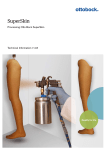
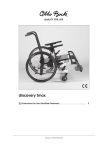
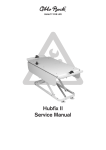
ScoutCrawler Service Manual Table of contents Table of contents 1 1.1 1.2 1.3 Introduction .........................................................................................................................................................3 Foreword .............................................................................................................................................3 Support ...............................................................................................................................................3 Product Overview .................................................................................................................................3 2 2.1 2.2 Safety ....................................................................................................................................................................3 Explanation of Warning Symbols .............................................................................................................3 General safety instructions .....................................................................................................................4 3 3.1 3.2 3.3 3.4 3.5 3.5.1 3.5.2 3.5.3 3.5.4 3.5.5 3.5.6 3.5.7 3.6 3.6.1 3.6.2 3.6.3 3.6.4 3.6.5 3.6.6 3.7 3.7.1 3.7.2 3.7.3 3.7.4 3.7.5 3.7.6 3.7.7 3.7.8 3.8 3.8.1 Service Work .......................................................................................................................................................4 General Information ..............................................................................................................................4 Maintenance Schedule ..........................................................................................................................5 Required Tools and Accessories .............................................................................................................5 Removing the Battery Pack ....................................................................................................................6 Electrical System ..................................................................................................................................6 Replacing the Retaining Strap ................................................................................................................6 Removing the Controller ........................................................................................................................7 Replacing the Battery Cables of the Battery Pack .....................................................................................7 Replacing the Control Panel...................................................................................................................8 Replacing the Motor Cable Set ...............................................................................................................8 Replacing the Controller ......................................................................................................................10 Installing the Controller ........................................................................................................................10 Frame ................................................................................................................................................10 Replacing the Attachment Straps ..........................................................................................................10 Replacing the Loading Ramp................................................................................................................11 Replacing the Floor Plate .....................................................................................................................11 Replacing the Wheel Stops ..................................................................................................................11 Replacing the Armrest .........................................................................................................................12 Replacing the Control Panel Holder ......................................................................................................13 Drive Unit ...........................................................................................................................................14 Removing the Crawler Tracks ...............................................................................................................14 Replacing the Crawler Track ................................................................................................................14 Replacing the Guide Wheels ................................................................................................................15 Replacing the Track Rollers ..................................................................................................................15 Removing the Drive Wheels ..................................................................................................................15 Replacing the Drive Motor ....................................................................................................................16 Installing the Drive Wheels ...................................................................................................................17 Installing the Crawler Tracks ................................................................................................................17 Installing the Battery Pack ....................................................................................................................18 Charging the Battery Pack ...................................................................................................................19 4 4.1 4.2 Appendices ........................................................................................................................................................19 Technical Data ....................................................................................................................................19 Maintenance Schedule ........................................................................................................................21 2 | Ottobock ScoutCrawler Introduction 1 Introduction 1.1 Foreword Regular maintenance is important – it improves safety and increases the lifespan of the product. All Mobility products should be inspected and serviced once a year. However, we recommend inspecting, readjusting, and if necessary servicing the product every 6 months if the product is used frequently or in case of frequent user changes. Only use original spare parts for all service and maintenance work. The service and maintenance tasks described here should only be completed by trained, qualified personnel and not by the user of the device. This service and maintenance manual refers to the respective spare parts catalogues and the instructions for use of the described products. Please use these documents together. Use the maintenance schedule (checklist) as a template for making copies. Retain completed maintenance sched ules and provide the customer with a copy. Instructions for Use (user) 647G692=* ScoutCrawler Outdoor Vehicle 1.2 Support Your national Ottobock team will be happy to answer any technical questions. The contact addresses and tele phone numbers can be found on the back inside cover of the service manual. 1.3 Product Overview 1 ScoutCrawler with accessories 1 Armrests 7 Battery charger 2 Transport case 8 Charging cable for external charging 3 enAble 40 control panel 9 Tool kit 4 Track drive 10 Battery pack 5 Battery case 11 Loading ramps 6 Cover cap 2 Safety 2.1 Explanation of Warning Symbols WARNING Warnings regarding possible risks of severe accident or injury. CAUTION Warnings regarding possible risks of accident or injury. NOTICE Warnings regarding possible technical damage. ScoutCrawler Ottobock | 3 Service Work 2.2 General safety instructions WARNING Non-observance of safety instructions Risk of pinching, crushing, tipping, falling, product malfunction/defect ► Observe all safety instructions in these instructions for use and in all other applicable documents. WARNING Incorrect settings Risk of falling, tipping over or improper user posture due to incorrect settings ► Adjustments may only be carried out by qualified personnel instructed by the manufacturer. ► Check for safe function before delivering the product. CAUTION Use of unsuitable tools Pinching, crushing or damaging the product ► When working, use only tools that are suitable for the conditions at the workplace and whose proper use ensures safety and health protection. NOTICE Improper preparation before making adjustments Risk of damage to the product ► When you work on the product, secure it so that it cannot tip over or fall over. ► Switch off the product for all adjustment tasks. Functional tests of the electrical components are excepted from this rule. ► Before performing any work on the crawler tracks, ensure sufficient protection against mechanical, chemical and thermal effects. NOTICE Re-use of self-locking nuts Unintended loosening of the screw connections ► Always replace self-locking nuts with new self-locking nuts after disassembly. 3 Service Work 3.1 General Information INFORMATION Read the service manual before starting work. Familiarise yourself with the functions of the product prior to inspection and use. In order to do so, you can request this service manual and other documentation from the manufacturer (see the overview of national Ottobock branches on the inside of the back cover) or download from our homepage www.ottobock.de or www.ottobock.com. INFORMATION Clean and disinfect the product before commencing service work. Observe all care instructions and product-specific inspection instructions in the instructions for use. INFORMATION Many screw connections utilise screws and nuts equipped with thread lock. If you loosen screw connections, be sure to replace the respective nut or screw with one equipped with a new thread lock. If new screws or nuts with thread lock are not available, apply a medium-strength liquid thread locking compound (such as Loctite® 241 or Euro Lock A24.20) to the existing screws. 4 | Ottobock ScoutCrawler Service Work 3.2 Maintenance Schedule Maintenance schedule as a template for copying: see Page 21. 3.3 Required Tools and Accessories The following tools are required in order to perform the service work: • Reversible ratchet handle wrench and sockets (size: 8 – 24) • Torque wrench (measurement range 5 - 50 Nm) • Wrench (size: 8 – 24) • Allen wrench (size: 2.5 – 6) • Screwdriver (blade width: 2.5/3.5/5 mm) • Phillips head screwdriver (size: 2) • Hammer (approx. 300 g); soft-faced hammer • Pliers: cutting pliers, combination pliers, snap ring pliers • Puller • Pin punch, ø 3/4/5/6 mm • Drill/twist drill ø 3.2/5/5.2/6 mm • Stanley knife with sickle hooked blade and standard blade • Workbench and vice with plastic jaws and rubber insert • Measurement equipment: rule, spirit level • Liquid thread lock “medium strength” ScoutCrawler Ottobock | 5 Service Work 3.4 Removing the Battery Pack Prior to all service tasks (except functional tests), turn off the control unit and remove the battery pack! After all service tasks, reinstall the battery pack and charge it if required. 1) Open the cover on the battery compartment (see Fig. 2). 2) Loosen the retaining strap on the battery pack (see Fig. 3). 3) Pull up on the lever of the battery plug plate (see Fig. 4). 4) Loosen the battery pack connections (see Fig. 5). 5) Remove the battery pack (see Fig. 6). 2 3 4 5 6 3.5 Electrical System 3.5.1 Replacing the Retaining Strap > 1) 2) 3) Preparation: Remove the battery pack (see Page 6). Pull out the retaining strap (not illustrated). Replace the retaining strap (not illustrated). Guide the retaining strap through the openings in the floor plate (see Fig. 7, item 1 and item 2). 6 | Ottobock ScoutCrawler Service Work 7 3.5.2 Removing the Controller > 1) 2) 3) Preparation: Remove the battery pack (see Page 6). Loosen the motor cables (see Fig. 8). Loosen and remove the 2 Allen head screws on the controller (see Fig. 9). Remove the controller (see Fig. 10). 8 9 10 3.5.3 Replacing the Battery Cables of the Battery Pack > 1) 2) 3) Preparation: Remove the battery pack (see Page 6), remove the controller (see Page 7). Disconnect the 2 battery cable plugs from the controller (see Fig. 11, item 2 and item 4). Replace the battery cables (not illustrated). Connect the 2 battery cable plugs to the controller (see Fig. 11, item 2 and item 4). ScoutCrawler Ottobock | 7 Service Work 11 3.5.4 Replacing the Control Panel > 1) 2) 3) 4) 5) 6) 7) Preparation: Remove the battery pack (see Page 6), remove the controller (see Page 7). Loosen the control panel cable on the controller (see Fig. 12, item 1). Remove the cable ties (see Fig. 13). Loosen and remove the 4 Allen head screws with the spring washers on the underside of the control panel (see Fig. 14). Replace the control panel (not illustrated). Insert and tighten the 4 Allen head screws with the spring washers on the underside of the control panel (see Fig. 14). Connect the control panel cable to the controller (see Fig. 12, item 1). Install the control panel cable and secure it with cable ties (not illustrated). 12 13 14 3.5.5 Replacing the Motor Cable Set > Preparation: Remove the battery pack (see Page 6), remove the controller (see Page 7). 1) Loosen the plugs of the motor cable set from the controller (see Fig. 15, item 3 and item 4). 2) Loosen and remove the 2 Allen head screws on the mounting plate (see Fig. 16). 8 | Ottobock ScoutCrawler Service Work 3) 4) 5) 6) 7) Remove the mounting plate including the motor cable set (not illustrated). Remove the motor cable set upwards out of the mounting plate (see Fig. 17). Remove the spring pin from the adapter housing (see Fig. 18). Pull the adapter housing off the motor connection cable (see Fig. 19). Replace the motor connection cable (not illustrated). INFORMATION: The motor connection cable must be threaded through the mounting plate from below. 8) Slide the adapter housing onto the motor connection cable (see Fig. 19) and secure it with the spring pin (see Fig. 18). 9) Insert the motor cable set into the mounting plate from above (see Fig. 17). 10) Insert the mounting plate in the corresponding position (not illustrated). 11) Insert and tighten the 2 Allen head screws in the mounting plate (see Fig. 16). 15 16 17 18 19 ScoutCrawler Ottobock | 9 Service Work 3.5.6 Replacing the Controller > 1) 2) 3) Preparation: Remove the battery pack (see Page 6), remove the controller (see Page 7). Loosen all connections on the controller (see Fig. 20). Replace the controller (not illustrated). Secure all connections on the controller (see Fig. 20). 20 3.5.7 Installing the Controller 1) Insert the controller in the proper position (not illustrated). 2) Insert and tighten the 2 Allen head screws on the controller (see Fig. 21). 3) Connect the 2 motor cables according to the colour-coded markings (see Fig. 22, item 1 and item 2). 21 22 3.6 Frame 3.6.1 Replacing the Attachment Straps 1) Loosen and remove the Allen head screw on the attachment strap (see Fig. 23). 2) Replace the attachment strap (not illustrated). 3) Insert and tighten the Allen head screw on the attachment strap (see Fig. 23). 10 | Ottobock ScoutCrawler Service Work 23 3.6.2 Replacing the Loading Ramp 1) Loosen and remove the 2 Allen head screws on the sides of the loading ramp (see Fig. 24). 2) Replace the loading ramp (not illustrated). 3) Insert and tighten the 2 Allen head screws on the sides of the loading ramp (see Fig. 24). 24 3.6.3 Replacing the Floor Plate 1) Loosen and remove the 2 Allen head screws on the floor plate (see Fig. 25). 2) Replace the floor plate (not illustrated). 3) Insert and tighten the 2 Allen head screws on the floor plate (see Fig. 25). 25 3.6.4 Replacing the Wheel Stops 1) 2) 3) 4) Loosen and remove the 2 quick clamps on the wheel stops (see Fig. 26, item 1 and item 2). Remove the holder (see Fig. 26, item 3) and the clamp piece (see Fig. 26, item 4) from the support. Replace the holder and the clamp piece (not illustrated). Position the holder (see Fig. 26, item 3) and the clamp piece (see Fig. 26, item 4) at the support. ScoutCrawler Ottobock | 11 Service Work 5) Insert and tighten the 2 quick clamps on the wheel stops (see Fig. 26, item 1 and item 2). 26 3.6.5 Replacing the Armrest 1) Loosen and remove the 3 Allen head screws with washers on the underside of the armrest (see Fig. 28 and see Fig. 29). 2) Pull off the armrest (not illustrated). 3) Replace the armrest (not illustrated). 4) Slide on the armrest (not illustrated). 5) Insert and tighten the 3 Allen head screws with washers on the underside of the armrest (see Fig. 28 and see Fig. 29). Side with control panel: 1) Remove the cable ties (see Fig. 27). 2) Loosen and remove the 3 Allen head screws with washers on the underside of the armrest (see Fig. 28 and see Fig. 29). 3) Pull out the control panel holder with the control panel to the front (not illustrated). 4) Pull off the armrest (not illustrated). 5) Replace the armrest (not illustrated). 6) Slide on the armrest and insert the control panel holder from the front (not illustrated). 7) Insert and tighten the 3 Allen head screws with washers on the underside of the armrest (see Fig. 28 and see Fig. 29). 8) Install the control panel cable and secure it with cable ties (not illustrated). INFORMATION: When fastening the cable, note that the wheel stops are height-adjustable. 27 12 | Ottobock 28 ScoutCrawler Service Work 29 3.6.6 Replacing the Control Panel Holder 1) Remove the cable ties (see Fig. 30). 2) Loosen and remove the 3 Allen head screws with washers on the underside of the armrest (see Fig. 31 and see Fig. 32). 3) Loosen and remove the 4 Allen head screws with the spring washers on the underside of the control panel (see Fig. 33). 4) Pull out the control panel holder to the front (not illustrated). 5) Replace the control panel holder (not illustrated). 6) Insert and tighten the 4 Allen head screws with the spring washers on the underside of the control panel (see Fig. 33). 7) Insert the control panel holder from the front (not illustrated). 8) Insert and tighten the 3 Allen head screws with washers on the underside of the armrest (see Fig. 31 and see Fig. 32). 9) Install the control panel cable and secure it with cable ties (not illustrated). INFORMATION: When fastening the cable, note that the wheel stops are height-adjustable. ScoutCrawler 30 31 32 33 Ottobock | 13 Service Work 3.7 Drive Unit 3.7.1 Removing the Crawler Tracks > 1) 2) 3) 4) 5) 6) Position the outdoor vehicle on a workbench and secure it against falling! INFORMATION: Ensure that all screws and components of the drive unit are accessible. Loosen the 2 motor cables (see Fig. 34). Loosen the guide wheel clamping screw (see Fig. 35, item 1). Release all tension on the guide wheel clamping screw (see Fig. 35, item 2). Loosen (see Fig. 36) and remove (see Fig. 37) the Allen head screw on the guide wheels. Remove the guide wheels (not illustrated). Remove the crawler track (see Fig. 38). 34 35 36 37 38 3.7.2 Replacing the Crawler Track > Preparation: Remove the crawler track (see Page 14). ► Replace the crawler track (not illustrated). 14 | Ottobock ScoutCrawler Service Work 3.7.3 Replacing the Guide Wheels > Preparation: Remove the crawler track (see Page 14). ► Replace the guide wheels (not illustrated). 3.7.4 Replacing the Track Rollers > 1) 2) 3) 4) 5) Preparation: Remove the crawler track (see Page 14). Remove the circlip with the circlip pliers (see Fig. 39). Remove the track rollers (see Fig. 40). Replace the track rollers (not illustrated). Slide on the track rollers (not illustrated). Insert the circlip using the circlip pliers (see Fig. 39). 39 40 3.7.5 Removing the Drive Wheels > Preparation: Remove the crawler track (see Page 14). 1) Loosen and remove the 2 Allen head screws on the drive wheels (see Fig. 42, item 1 and item 13) (see Fig. 41). 2) Loosen and remove the 2 washers (see Fig. 42, item 2 and item 12). 3) Remove the 2 drive wheels (see Fig. 42, item 3 and item 11) (see Fig. 43). 41 ScoutCrawler 42 Ottobock | 15 Service Work 43 3.7.6 Replacing the Drive Motor > Preparation: Remove the crawler tracks (see Page 14), remove the drive wheels (see Page 15). 1) Loosen and remove the 2 cams (see Fig. 46, item 4 and item 10) on the drive wheels using the puller (see Fig. 44). 2) Loosen and remove the 2 washers from the drive axles (see Fig. 46, item 5 and item 9). 3) Remove the cable ties on the motor cables (not illustrated). 4) Loosen and remove the 2 Allen head screws on the motor mount (see Fig. 45). 5) Remove the drive motor (not illustrated). 6) Replace the drive motor (not illustrated). 7) Insert the drive motor (not illustrated). 8) Insert and tighten the 2 Allen head screws on the motor mount (see Fig. 45). 9) Slide the 2 washers onto the drive axles (see Fig. 46, item 5 and item 9). 10) Slide the 2 cams (see Fig. 46, item 4 and item 10) for the drive wheels onto the feather key and tap them in place with the soft-faced hammer (not illustrated). 44 45 46 16 | Ottobock ScoutCrawler Service Work 3.7.7 Installing the Drive Wheels 1) Slide the 2 drive wheels (see Fig. 48, item 3 and item 11) onto the cams (see Fig. 47). 2) Slide on the 2 washers (see Fig. 48, item 2 and item 12). 3) Insert and tighten the 2 Allen head screws (see Fig. 48, item 1 and item 13) on the drive wheels (see Fig. 49). 47 48 49 3.7.8 Installing the Crawler Tracks 1) Apply the crawler track (not illustrated). 2) Position the spacer sleeve (see Fig. 50, item 5) within the axle adapter (not illustrated). 3) Position the 2 spacers (see Fig. 50, item 4 and item 6) outside the axle adapter (not illustrated). 4) Slide the 2 guide wheels (see Fig. 50, item 3 and item 7) onto the spacers (not illustrated). 5) Apply the 2 washers (see Fig. 50, item 2 and item 8) (not illustrated). 6) Insert (see Fig. 51) and tighten (see Fig. 52) the guide wheel screw (see Fig. 50, item 9). 7) Tighten the crawler track as described in the instructions for use (647G692) (see Fig. 53). 8) Secure the clamping screw (see Fig. 54). 9) Connect the 2 motor cables according to the colour-coded markings (see Fig. 55, item 1 and item 2). 10) If needed: Install the motor cables and secure them with cable ties (not illustrated). ScoutCrawler Ottobock | 17 Service Work 50 51 52 53 54 55 3.8 Installing the Battery Pack After all service tasks, reinstall the battery pack and charge it if required. > All service tasks are completed. 1) Open the battery compartment cover (not illustrated). 2) Lay the battery pack retaining strap to the outside (not illustrated). 3) Insert the battery pack (not illustrated). 4) Slide the battery pack plug plate onto the battery pack (see Fig. 56 and see Fig. 57). INFORMATION: Ensure that the lever on the battery pack plug plate engages on the battery pack. → When the LEDs on the battery pack plug plate light up, this indicates that the connection was correctly established and none of the batteries are defective. 5) Fasten and tighten the battery pack retaining strap (see Fig. 58). 6) Close the battery compartment cover (see Fig. 59). 18 | Ottobock ScoutCrawler Appendices 56 57 58 59 3.8.1 Charging the Battery Pack ► Charge the battery pack as described in the instructions for use (647G692) (not illustrated). 4 Appendices 4.1 Technical Data Dimensions and weights Armrest height Armrest length Max. drive-in width Drive-in height Ramp angle Overall width Overall height Overall length (ramp folded up) Overall length (ramp folded down) Weight when empty Transport weights Max. load capacity Crawler track tension 665 – 740 mm 260 mm 665 mm 152 mm 14° 1090 mm 940 mm (joystick) 980 mm 1364 mm 59.4 kg See empty weight, thereof: Crawler track drive (left /right): each 14.5 kg Transport case (left): 5.1 kg Battery case (right): 5.6 kg All tubes: 7.8 kg Loading ramps: 4.4 kg Battery pack: 7.5 kg 145 kg (120 kg user + max. 25 kg manual wheelchair) Crawler track slack 1.5 cm at 3 kg weight Adaptation of manual wheelchairs Max. drive-in width 665 mm ScoutCrawler Ottobock | 19 Appendices Adaptation of manual wheelchairs Connection system Compatibility with manual wheelchairs Three belt straps with carabiners Two tyre stops Adaptable to most manual wheelchair models common in the market Observe the maximum drive-in width! Observe the length of the outdoor vehicle! Electrical system IP protection class (according to DIN EN 60529) Operating voltage Batteries: Li-Ion Charging time (drained battery) Motor power IP protection class (according to DIN EN 60529) Self-contacting Battery lifetime (complete charging cycles) Battery charger Control Unit Model IP protection class (according to DIN EN 60529) Operating voltage Max. output current per motor Driving data Speed Maximum climbing ability Maximum fording depth Maximum obstacle height Range Operating temperature Transportation and storage temperature range 20 | Ottobock IP X4 24 V DC 2 x 24 V; 18.4 Ah (=24 V / 36,8 Ah) Approx. 8 h 2x 250 watts IP 66 Yes 700 cycles (subsequently 80% charging capacity) For details, see the instructions for use supplied with the battery charger. enAble40 IP 54 24 V DC 75 A 6 km/h 30 % (less depending on user ability, surface and load) 100 mm 40 mm Approx. 12 km (less depending on the grade, surface and load) -15 °C to +50 °C -10 °C to +40 °C (at 45 – 85 % relative humidity) ScoutCrawler Appendices 4.2 Maintenance Schedule Maintenance Schedule Area Assembly Mobility base ScoutCrawler Inspection (checklist) 1. Function/setting Customer: 2. Inspected for dam age/deformation X X X X X X X X X X X X X X X X X X Frame Safety belt left Safety belt right Safety belt centre Loading ramp left Loading ramp right Platform left Platform right Bowden cable left Bowden cable right Armrest left Armrest right Control panel holder Wheel stop left Wheel stop right Battery case Transport case Closures (battery case/ transport case) Holders (battery case/ X transport case) Electrical System Control panel X Battery pack X Battery pack holder X Battery pack retaining strap X Battery pack cables X Controller cable holder X Controller cables X Controller X Drive motor cables X Drive train Crawler track left X Crawler track right X Crawler track tensioning device left X Crawler track tensioning device right X Guide wheels left X Guide wheels right X Track rollers left X Track rollers right X Drive motor left X Drive motor right X Drive wheels left X Drive wheels right X Do the settings on the ScoutCrawler outdoor vehicle meet the needs of the user? The maintenance service was performed by: on: ScoutCrawler 3. Screw connections inspected X X X X X X X X X X X X X X X X X X X X X X X X X X X X X X X X X X Ottobock | 21 22 | Ottobock ScoutCrawler Kundenservice/Customer Service Europe Otto Bock HealthCare Deutschland GmbH Max-Näder-Str. 15 · 37115 Duderstadt · Germany T +49 (0) 5527 848-3433 · F +49 (0) 5527 848-1460 [email protected] · www.ottobock.de Otto Bock Healthcare Products GmbH Kaiserstraße 39 · 1070 Wien · Austria T +43 (0) 1 5269548 · F +43 (0) 1 5267985 [email protected] · www.ottobock.at Otto Bock Adria Sarajevo D.O.O. Omladinskih radnih brigada 5 71000 Sarajevo · Bosnia-Herzegovina T +387 (0) 33 766200 · F +387 (0) 33 766201 [email protected] · www.ottobockadria.com.ba Otto Bock Bulgaria Ltd. 41 Tzar Boris III‘ Blvd. · 1612 Sofia · Bulgaria T +359 (0) 2 80 57 980 · F +359 (0) 2 80 57 982 [email protected] · www.ottobock.bg Otto Bock Suisse AG Pilatusstrasse 2 · CH-6036 Dierikon T +41 (0) 41 455 61 71 · F +41 (0) 41 455 61 70 [email protected] · www.ottobock.ch Otto Bock ČR s.r.o. Protetická 460 · 33008 Zruč-Senec · Czech Republic T +420 (0) 377825044 · F +420 (0) 377825036 [email protected] · www.ottobock.cz Otto Bock Iberica S.A. C/Majada, 1 · 28760 Tres Cantos (Madrid) · Spain T +34 (0) 91 8063000 · F +34 (0) 91 8060415 [email protected] · www.ottobock.es Otto Bock France SNC 4 rue de la Réunion - CS 90011 91978 Courtaboeuf Cedex · France T +33 (0) 1 69188830 · F +33 (0) 1 69071802 [email protected] · www.ottobock.fr Otto Bock Healthcare plc 32, Parsonage Road · Englefield Green Egham, Surrey TW20 0LD · United Kingdom T +44 (0) 1784 744900 · F +44 (0) 1784 744901 [email protected] · www.ottobock.co.uk Otto Bock Hungária Kft. Tatai út 74. · 1135 Budapest · Hungary T +36 (0) 1 4511020 · F +36 (0) 1 4511021 [email protected] · www.ottobock.hu Otto Bock Adria d.o.o. Dr. Franje Tuđmana 14 ·10431 Sveta Nedelja · Croatia T +385 (0) 1 3361 544 · F +385 (0) 1 3365 986 [email protected] · www.ottobock.hr OOO Otto Bock Service p/o Pultikovo, Business Park „Greenwood“, Building 7, 69 km MKAD 143441 Moscow Region/Krasnogorskiy Rayon Russian Federation T +7 (0) 495 564 8360 · F +7 (0) 495 564 8363 [email protected] · www.ottobock.ru Otto Bock HealthCare Two Carlson Parkway North, Suite 100 Minneapolis, MN 55447 · USA T +1 (0) 763 553 9464 · F +1 (0) 763 519 6153 [email protected] www.ottobockus.com Otto Bock Scandinavia AB Koppargatan 3 · Box 623 · 60114 Norrköping · Sweden T +46 (0) 11 280600 · F +46 (0) 11 312005 [email protected] · www.ottobock.se Asia/Pacific Otto Bock Slovakia s.r.o. Röntgenova 26 · 851 01 Bratislava 5 · Slovak Republic T +421 (0) 2 32 78 20 70 · F +421 (0) 2 32 78 20 89 [email protected] · www.ottobock.sk Otto Bock Sava d.o.o. Maksima Gorkog bb · 18000 Niš · Republika Srbija T +381 (0) 18 4285888 · F +381 (0) 18 4539191 [email protected] · www.ottobock.rs Otto Bock Ortopedi ve Rehabilitasyon Tekniği Ltd. Şti. Ali Dursun Bey Caddesi · Lati Lokum Sokak Meriç Sitesi B Block No: 6/1 34387 Mecidiyeköy-İstanbul · Turkey T +90 (0) 212 3565040 · F +90 (0) 212 3566688 [email protected] · www.ottobock.com.tr Africa Otto Bock Algérie E.U.R.L. 32, rue Ahcène Outaleb - Coopérative les Mimosas Mackle-Ben Aknoun · Alger · DZ Algérie T +213 (0) 21 913863 · F +213 (0) 21 913863 [email protected] · www.ottobock.fr Otto Bock Egypt S.A.E. 28 Soliman Abaza St. Mohandessein - Giza · Egypt T +202 (0) 330 24 390 · F +202 (0) 330 24 380 [email protected] · www.ottobock.com.eg Otto Bock South Africa (Pty) Ltd Building 3 Thornhill Office Park · 94 Bekker Road Midrand · Johannesburg · South Africa T +27 (0) 11 312 1255 [email protected] www.ottobock.co.za Americas Otto Bock Italia Srl Us Via Filippo Turati 5/7 · 40054 Budrio (BO) · Italy T +39 (0) 051 692-4711 · F +39 (0) 051 692-4720 [email protected] · www.ottobock.it Otto Bock Argentina S.A. Av. Cabildo 924 · CP 1426 Ciudad Autônoma de Buenos Aires · Argentina T +54 (0) 11 4706-2255 · F +54 (0) 11 4788-3006 [email protected] www.ottobock.com.ar Otto Bock Benelux B.V. Ekkersrijt 1412 · 5692 AK Son en Breugel · The Netherlands T +31 (0) 499 474585 · F +31 (0) 499 476250 [email protected] · www.ottobock.nl Otto Bock do Brasil Ltda. Rua Jovelino Aparecido Miguel, 32 13051-030 Campinas-São Paulo · Brasil T +55 (0) 19 3729 3500 · F +55 (0) 19 3269 6061 [email protected] · www.ottobock.com.br Industria Ortopédica Otto Bock Unip. Lda. Av. Miguel Bombarda, 21 - 2º Esq. 1050-161 Lisboa · Portugal T +351 (0) 21 3535587 · F +351 (0) 21 3535590 [email protected] Otto Bock HealthCare Canada 5470 Harvester Road Burlington, Ontario, L7L 5N5, Canada T +1 (0) 289 288-4848 · F +1 (0) 289 288-4837 [email protected] · www.ottobock.ca Otto Bock Polska Sp. z o. o. Ulica Koralowa 3 · 61-029 Poznań · Poland T +48 (0) 61 6538250 · F +48 (0) 61 6538031 [email protected] · www.ottobock.pl Otto Bock HealthCare Andina Ltda. Clínica Universitária Teletón, Autopista Norte km 21 La Caro Chia, Cundinamarca · Bogotá · Colombia T +57 (0) 1 8619988 · F +57 (0) 1 8619977 [email protected] · www.ottobock.com.co Otto Bock Romania srl Şos de Centura Chitila - Mogoşoia Nr. 3 077405 Chitila, Jud. Ilfov · Romania T +40 (0) 21 4363110 · F +40 (0) 21 4363023 [email protected] · www.ottobock.ro Otto Bock de Mexico S.A. de C.V. Prolongación Calle 18 No. 178-A Col. San Pedro de los Pinos C.P. 01180 México, D.F. · Mexico T +52 (0) 55 5575 0290 · F +52 (0) 55 5575 0234 [email protected] · www.ottobock.com.mx Otto Bock Australia Pty. Ltd. Suite 1.01, Century Corporate Centre 62 Norwest Boulevarde Baulkham Hills NSW 2153 · Australia T +61 (0) 2 8818 2800 · F +61 (0) 2 8814 4500 [email protected] · www.ottobock.com.au Beijing Otto Bock Orthopaedic Industries Co., Ltd. B12E, Universal Business Park 10 Jiuxianqiao Road, Chao Yang District Beijing, 100015, P.R. China T +8610 (0) 8598 6880 · F +8610 (0) 8598 0040 [email protected] www.ottobock.com.cn Otto Bock Asia Pacific Ltd. Suite 3218, 32/F., Sun Hung Kai Centre 30 Harbour Road, Wanchai, Hong Kong · China T +852 (0) 2598 9772 · F +852 (0) 2598 7886 [email protected] Otto Bock HealthCare India Behind FairLawn Housing Society St. Gregorios Lane, Sion Trombay Road Chembur, Mumbai, 400071 · India T +91 (0) 22 2520 1268 · F +91 (0) 22 2520 1267 [email protected] · www.ottobock.in Otto Bock Japan K. K. Yokogawa Building 8F, 4-4-44 Shibaura Minato-ku, Tokyo, 108-0023 · Japan T +81 (0) 3 3798-2111 · F +81 (0) 3 3798-2112 [email protected] · www.ottobock.co.jp Otto Bock Korea HealthCare Inc. 4F Agaworld Building · 1357-74, Seocho-dong Seocho-ku, 137-070 Seoul · Korea T +82 (0) 2 577-3831 · F +82 (0) 2 577-3828 [email protected] · www.ottobockkorea.com Otto Bock South East Asia Co., Ltd. 1741 Phaholyothin Road Kwaeng Chatuchark · Khet Chatuchark Bangkok 10900 · Thailand T +66 (0) 2 930 3030 · F +66 (0) 2 930 3311 [email protected] · www.ottobock.co.th Other countries Otto Bock HealthCare GmbH Max-Näder-Straße 15 · 37115 Duderstadt · Germany T +49 (0) 5527 848-1590 · F +49 (0) 5527 848-1676 [email protected] · www.ottobock.com Your specialist dealer Otto Bock Mobility Solutions GmbH Lindenstraße 13 · 07426 Königsee/Germany T +49 (0) 69 9999 9393 · F +49 (0) 69 9999 9392 [email protected] · www.ottobock.com Ottobock has a certified Quality Management System in accordance with ISO 13485. Template-Version: 2012-07-04 © Ottobock · 647G693=EN-01-1210 Versandanschrift für Rücksendungen/Adress for Returns: Otto Bock Manufacturing Königsee GmbH Lindenstraße 13 · 07426 Königsee/Germany