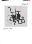
1
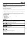
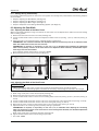
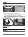
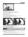
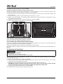
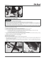
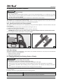
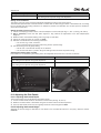
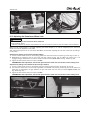
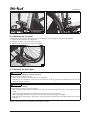
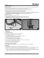
discovery tmax Instructions for Use (Qualified Personnel) ............................................... © Ottobock · 647G734=EN-03-1201 3 2 01/2012 Table of contents Table of contents 1 Foreword .................................................................................................................................................................5 2 Application ..............................................................................................................................................................5 2.1 Intended Use ...............................................................................................................................................5 2.2 Indications ...................................................................................................................................................5 2.3 Contraindications ........................................................................................................................................5 2.4 Required Qualifications ...............................................................................................................................5 3 Safety ......................................................................................................................................................................6 3.1 Explanation of Warning Symbols ................................................................................................................6 3.2 General Safety Instructions.........................................................................................................................6 3.3 Safety instructions for assembly .................................................................................................................7 3.4 Type Plate ....................................................................................................................................................7 4 Delivery ...................................................................................................................................................................7 4.1 Scope of Delivery ........................................................................................................................................7 4.2 Options ........................................................................................................................................................8 4.3 Storage ........................................................................................................................................................8 5 Preparation for Use ................................................................................................................................................8 5.1 Tools required .............................................................................................................................................8 5.2 Assembly .....................................................................................................................................................8 6 Adjustments ............................................................................................................................................................9 6.1 Prerequisites ...............................................................................................................................................9 6.1.1 Settings during Preassembly ..........................................................................................................10 6.2 Adjusting the Seat Width ...........................................................................................................................10 6.2.1 Adjusting the Width of the Main Frame ...........................................................................................10 6.2.2 Adjusting the Width of the Seat Frame ...........................................................................................10 6.3 Adjusting the Seat Depth ..........................................................................................................................11 6.4 Adjusting the Back Angle ..........................................................................................................................11 6.5 Adaptation of the Seating Shell/Seating System .....................................................................................12 6.5.1 Installing a Seating Shell – Otto Bock Shape System (Option) .......................................................12 6.5.2 Removing/Installing a Seat Plate (Option) ......................................................................................12 6.5.3 Installing Otto Bock Back Systems (Option) ...................................................................................13 6.5.4 Installing other Seating Systems/Back Systems..............................................................................13 6.6 Adjusting the Seat Height .........................................................................................................................13 6.7 Adjusting the Locking Pedal ......................................................................................................................14 6.8 Adjusting the Footrests/Footplates ..........................................................................................................15 6.8.1 Adjusting the Depth of the Footrest Adapter ..................................................................................15 6.8.2 Other Settings ................................................................................................................................15 6.9 Checking/Adjusting the Seating Centre of Gravity ...................................................................................15 6.10 Adjusting the Side Panels .........................................................................................................................16 6.10.1 Adjusting the Armrest Depth ...........................................................................................................16 6.10.2 Adjusting the Armrest Height ..........................................................................................................16 6.11 Adjusting the Wheel Adapters ...................................................................................................................17 6.12 Adjusting the Knee Lever Wheel Lock .......................................................................................................18 6.13 Adjusting the Tip Assist .............................................................................................................................19 6.14 Adjusting the Anti-Tipper ...........................................................................................................................19 7 Handover ..............................................................................................................................................................20 7.1 Final Inspection .........................................................................................................................................20 7.2 Transport to the customer ........................................................................................................................20 7.3 Delivery ......................................................................................................................................................20 8 Maintenance/Repair .............................................................................................................................................21 01/2012 3 Table of contents 9 Disposal ................................................................................................................................................................21 9.1 Disposal information .................................................................................................................................21 9.2 Information on Re-Use ..............................................................................................................................21 10 Legal Information .................................................................................................................................................21 10.1 Liability.......................................................................................................................................................21 10.2 CE Conformity ...........................................................................................................................................21 10.3 Warranty Terms and Conditions ................................................................................................................21 11 Appendices ...........................................................................................................................................................21 11.1 Technical Data ..........................................................................................................................................21 4 01/2012 Foreword 1 Foreword INFORMATION Date of the last update: 2012-01-20 ► Please read this document carefully. ► Follow the safety instructions. INFORMATION Missing instructions for use can be downloaded from the homepage at www.ottobock.com or ordered directly from Otto Bock Service (see back cover or inside back cover for addresses). The product was delivered as specified on the order form. Settings must be adjusted and the product must be finetuned according to the medical indications or the needs of the user; this must be done in the presence of the user. These instructions for use provide the information necessary for adjusting the settings. Adjustments should be made in close cooperation with the user or attendant. Please note the following: • The Instructions for Use (Authorised Personnel) are intended only for qualified authorised personnel and remain with them. • The operation of the product is described in the Instructions for Use (User). These instructions must be given to the user or attendant. • We recommend checking the product settings regularly in order to assure optimal fit over the long term. A fitting is required every six months for children and youth in particular. • The installation/refitting of all optional components is generally described in the service manual. • Otto Bock assumes no liability for combinations with seating systems that have not been approved by Otto Bock (see Page 21). 2 Application 2.1 Intended Use The wheelchair is intended exclusively for the adaptation of seating shells and other orthopaedic seating systems for people who are unable to walk or have walking impediments. It can be operated either by the user or by an attendant. The product can be used indoors and outdoors. In order to provide an optimised, individual fitting, it is adjustable and/or adaptable. The product may only be used with the options which are listed in the product order form. The Otto Bock warranty applies only when the product is used according to the specified conditions and for the inten ded purposes. 2.2 Indications This wheelchair is suitable for fittings for users in all age groups. The use of various orthopaedic seating systems (e.g. seating shells) and the variety of adjustment possibilities make the wheelchair suitable for use in case of inability to walk/walking impediments, e.g. due to: • Paralysis (paraplegia/tetraplegia) • Loss of limbs (leg amputation) • Limb defect/deformity • Joint contractures/defects • Neurological and muscular diseases 2.3 Contraindications None. 2.4 Required Qualifications The adjustment tasks described below are necessary for optimum adaptation to the respective seating system, and may only be completed by qualified, authorised personnel (orthopaedic authorised personnel, specialist dealers for rehabilitation products). 01/2012 5 Safety 3 Safety 3.1 Explanation of Warning Symbols WARNING Warnings regarding possible risks of severe accident or injury. CAUTION Warnings regarding possible risks of accident or injury. NOTICE Warnings regarding possible technical damage. 3.2 General Safety Instructions WARNING Incorrect settings Risk of falling, tipping over or improper user posture ► Adjustments may be carried out only by qualified personnel instructed by Otto Bock. ► Only the settings described in these instructions for use may be carried out. ► Settings may only be changed within the allowable adjustment ranges; otherwise, the stability of the product may be impaired (see this chapter and the chapter "Appendixes"). Please contact Otto Bock if you have any ques tions. ► Only conduct tests in the presence of an assistant. ► Unless expressly described, you should not change any settings with a person sitting in the product. ► Secure the user against falling out during all tests. ► Activate the anti-tipper during all tests. ► Before testing setting changes with the user seated, firmly tighten all screw connections. ► Check for safe function before handing over the product. WARNING Lack of instruction Risk of falling, tipping over ► Instruct the user in the proper use of the product when handing it over. ► Otto Bock recommends the preparation of an acceptance protocol. CAUTION Wearing unsuitable work clothing Risk of pinching, crushing, being pulled in ► Wear suitable work clothing and, for example, gloves and protective eyewear as necessary when working on the product. CAUTION Use of unsuitable tools Pinching, crushing or damaging the product ► When working, use only tools that are suitable for the conditions at the workplace and whose proper use ensures safety and health protection. NOTICE Tipping or falling of the product Damage to the product ► When you work on the product, secure it so that it cannot tip over or fall over. ► Use a clamping device to secure the product for all work at a workbench. NOTICE Wrong packaging Risk of damage to the product ► Use only the original packaging for delivery of the product. 6 01/2012 Delivery 3.3 Safety instructions for assembly CAUTION Unsecured screw connections Risk of pinching, crushing, tipping over, falling of user ► After all adjusting/readjusting work, retighten the mounting screws/nuts firmly. Observe any torque settings which may be specified. ► Any time you loosen a screw connection with thread lock, replace it with a new screw connection or secure the old screw connection with medium strength thread locker (e.g. Loctite 241®). CAUTION Improper use of self-locking nuts Risk of the user falling or tipping over ► Always replace self-locking nuts with new self-locking nuts after disassembly. CAUTION Improper assembly of the removable wheels Risk of the user falling or tipping over ► After each assembly, verify the proper fit of the removable wheels. The quick-release axles must be firmly locked in the wheel attachment. 3.4 Type Plate Label A B C D E F The type label is located on the front connect G H ing tube of the base frame. Meaning Type designation Manufacturer article number Maximum load capacity (see the chapter "Technical Data") Manufacturer information/address/country Serial number European Article Number/Global Trade Item Number Read the instructions for use before using the product. CE marking – product safety according to EU guidelines Seat angle setting indicator ° (Only in case of anchor point system installation) Mounting point/anchor point system for attaching the product in a wheelchair accessible vehicle 4 Delivery 4.1 Scope of Delivery The product is delivered pre-assembled, with the rear wheels removed (in case of the plug-on version) and packed in a crate. The scope of delivery includes: • Pre-assembled wheelchair • 2 rear wheels (screwed or plug-on) • Footrests • Options as ordered • Instructions for Use (Authorised Personnel)/Instructions for Use (User) 01/2012 7 Preparation for Use INFORMATION Only provide the Instructions for Use (User) to the user. Seating shells/seat cushions are not included in the scope of delivery and must be ordered separately. 4.2 Options The functionality and operation of the options are described in more detail in the instructions for use (user). All of the available options/accessories are listed on the order form. 4.3 Storage The wheelchair must be stored in a dry place. For transportation and storage, an ambient temperature between -10 °C and +40 °C must be maintained. During extended storage, the knee lever wheel lock on wheelchairs with PU tyres must be released since tyre deforma tion may otherwise result. Note regarding the tires • Tires contain chemical substances that can react with other chemical substances (such as cleaning agents, acids, etc.). • Direct exposure to sunlight/UV radiation causes the tires to age more quickly. As a result, the tread surface hardens and corner pieces break out of the tread. • Avoid unnecessary parking outdoors. The tires should be replaced every 2 years regardless of wear and tear. 5 Preparation for Use 5.1 Tools required The following tools are required to make fine adjustments/setting changes: • Allen key, size 3/4/5 mm • Ring/open-end wrench, size 10/19/24 • Socket wrench, size 10/19 • Phillips screwdriver, size 2 • Flat screwdriver, size 3 • Torque wrench (measurement range 5-50 Nm) 5.2 Assembly CAUTION Loss of stability due to additional objects on the product Tipping, falling from the seating shell/seating system, breakage of load-bearing components ► Do not attach additional objects to the frame, cross tubes or seat. CAUTION Breakage of load-bearing components due to overloading Falling, tipping, injuries due to frame breakage ► Do not exceed the maximum load capacity (see chapter "Technical Data"). CAUTION Improper assembly of the removable wheels Risk of the user falling or tipping over ► After each assembly, verify the proper fit of the removable wheels. The quick-release axles must be firmly locked in the wheel attachment. CAUTION Incorrect air pressure Risk of falling, uncontrolled driving characteristics, tire rupture ► Maintain sufficient air pressure. Do not exceed the maximum specifications when filling the tires (see the chapter "Technical Data"). ► Do not use the wheelchair with over/under-inflated or unequally inflated tires. ► Note that a single tire with low air pressure can lead to uncontrolled driving characteristics. ► Note that low rear tire pressure can reduce the braking force of the knee lever wheel lock. 8 01/2012 Adjustments INFORMATION In general, only metric screws are used on the product. Exception: axle mounting of the 12" rear wheels (1/2" hexagon head screw + hexagon nut) INFORMATION With the combination of Allen head screw/hexagon nut, a higher torque can be transmitted using the hexagon nut than the Allen head screw. Please note that the Allen head screw is only intended to be held in place so it does not turn when tightening/loosen ing the hexagon nut. 1) For plug-on rear wheels: slide the rear wheels onto the wheel attachments of the wheel adapters. The quickrelease axles must not be removable after releasing the pushbutton. 2) Slide the footrests into the holders on the front frame tube. 3) Fold the footplates down. If necessary, insert the calf band and adjust it. 4) Prior to the adaptation of the seating shell/seating system, further wheelchair settings must be adjusted as required (see Page 9 et. seq.). 6 Adjustments 6.1 Prerequisites WARNING Incorrect settings Risk of falling, tipping over or improper user posture ► Adjustments may be carried out only by qualified personnel instructed by Otto Bock. ► Only the settings described in these instructions for use may be carried out. ► Settings may only be changed within the allowable adjustment ranges; otherwise, the stability of the product may be impaired (see this chapter and the chapter "Appendixes"). Please contact Otto Bock if you have any ques tions. ► Only conduct tests in the presence of an assistant. ► Unless expressly described, you should not change any settings with a person sitting in the product. ► Secure the user against falling out during all tests. ► Activate the anti-tipper during all tests. ► Before testing setting changes with the user seated, firmly tighten all screw connections. ► Check for safe function before handing over the product. WARNING Failure to verify tipping resistance Risk of the user falling or tipping over ► Changing the settings can lead to instability of the system as a whole. Verify tipping resistance after any changes to the settings. CAUTION Unsecured screw connections Risk of pinching, crushing, tipping over, falling of user ► After all adjusting/readjusting work, retighten the mounting screws/nuts firmly. Observe any torque settings which may be specified. ► Any time you loosen a screw connection with thread lock, replace it with a new screw connection or secure the old screw connection with medium strength thread locker (e.g. Loctite 241®). CAUTION Improper use of self-locking nuts Risk of the user falling or tipping over ► Always replace self-locking nuts with new self-locking nuts after disassembly. Fine adjustments and setting changes to match the concrete physical and mental condition of the user should always be made in the user's presence. All parts of the product should be cleaned thoroughly before adjustments are made. 01/2012 9 Adjustments 6.1.1 Settings during Preassembly If the seating shell/seating system as well as the back system have already been preassembled, the following chapters can be omitted: • Chapter "Adjusting the Seat Width" (see Page 10) • Chapter "Adjusting the Seat Depth" (see Page 11) • Chapter "Adjusting the Back Angle" (see Page 11) • Chapter "Adaptation of the Seating Shell/Seating System" (see Page 12) 6.2 Adjusting the Seat Width 6.2.1 Adjusting the Width of the Main Frame Within the allowable adjustment range, the width of the main frame can be adapted to the width of the chosen seating shell or seating system: 1) Remove the seat frame from the main frame (see Page 13). 2) Loosen 4 x Allen head screws on each of the adjustment tubes at the rear (see Fig. 1, item 1) and front (see Fig. 2, item 2). 3) Adapt the width on the adjustment tubes, preferably making it symmetrical. INFORMATION: The connection between the adjustment tube and frame always has to be realised on both sides with 2 Allen head screws (use inner 2 bores). INFORMATION: If required, an asymmetry of 12.5 mm (1/2") is allowable when adapting the adjustment tubes. The asymmetry must be on the same side on all adjustment tubes. However, the allowable adjust ment range must not be exceeded. Firmly retighten all Allen head screws to a torque of 10 Nm. 4) Mount the seat frame on the main frame (see Page 13). 1 2 6.2.2 Adjusting the Width of the Seat Frame INFORMATION ► Before adjusting the seat frame, the main frame needs to be adjusted (see the preceding chapter). ► In case of a seating shell/seating system preinstalled at the factory, these settings do not have to be changed. The width of the seat frame can be adapted to the width of the chosen seating shell or seating system. 1) When using a seat plate: remove the seat plate (see Page 12). 2) Remove the seat frame from the main frame (see Page 13). 3) Loosen 4 x Allen head screws on each of the connecting tubes at the front (see Fig. 3, item 1) and rear (see Fig. 3, item 2). 4) Loosen 2 x Allen head screws with counter nuts on the connecting tube of the central seat fork (see Fig. 3, item 3). 5) Loosen 2 x Allen head screws with counter nuts on the locking bar (see Fig. 3, item 4). 6) With push bar option: loosen 2 x Allen head screws on the connecting tube (see Fig. 4, item 5). 7) Adjust the width on all connecting tubes, preferably making it symmetrical. INFORMATION: If required, an asymmetry of 12.5 mm (1/2") is allowable when adapting the connecting tubes. The asymmetry must be on the same side on all connecting tubes. However, the allowable adjustment range must not be exceeded. When using a seat plate: reinstall the seat plate (see Page 12). 8) Tighten all Allen head screws to the following torque values: → Item 1/2/3: 10 Nm 10 01/2012 Adjustments → Item 4: Allen head screws – 8 Nm; counter nut – 10 Nm → Item 5: 8 Nm ► Mount the seat frame on the main frame (see Page 13). 3 4 6.3 Adjusting the Seat Depth The seat depth can be changed by vertically adjusting the back tubes on the seat frame. 1) When using a seat plate: remove the seat plate (see Page 12). 2) Loosen 2 x Allen head screws on the back plate/seat frame connection on both sides (see Fig. 5, item 1) and remove the rear connecting tube (see Fig. 6, item 1). 3) If a lashing point is installed, also loosen the 1 x Allen head screw /1 x pin (see Fig. 5, item 2/3). 4) Adjust the seat depth: slide the back plates to the desired depth position (see Fig. 6, item 2). INFORMATION: Ensure that the angle position is not changed (use the same bore). After adjusting the back plate, reinstall the rear connecting tube. 5) When using a seat plate: reinstall the seat plate (see Page 12). 6) Tighten all Allen head screws to 10 Nm. 5 6 6.4 Adjusting the Back Angle CAUTION Unallowable back angle Risk of the user falling or tipping over ► A back angle setting greater than 30° is not permitted. INFORMATION ► Ensure the angle setting is symmetrical on both sides of the back frame. ► Note that the seating position may have to be readjusted for an optimum seating centre of gravity. The back angle can be adjusted from -5° to +30° off the vertical position. 01/2012 11 Adjustments +30° -5° 7 a) Angle adjustment in 10° increments 1) Loosen the upper Allen head screw on the back plate (see Fig. 8, item 1). 2) Loosen and remove the angle adjustment screw on the back plate (see Fig. 8, item 2). 3) Adjust the backrest to the desired angle with the help of the existing bores. 4) Tighten all Allen head screws to 10 Nm. 5) Proceed the same way on the other side. b) Setting 5° interim angles 1) Loosen the front Allen head screw (see Fig. 9, item 1). 2) Loosen and remove the rear Allen head screw (see Fig. 9, item 2). 3) With installed lashing point: loosen 1 x Allen head screw/1 x anchor point (see Fig. 9, item 3). 4) Adjust the backrest angle by 5°. Use the available bore for this purpose. 5) Tighten all Allen head screws to 10 Nm. 6) Proceed the same way on the other side. 5° 8 9 6.5 Adaptation of the Seating Shell/Seating System 6.5.1 Installing a Seating Shell – Otto Bock Shape System (Option) This option may only be installed by Otto Bock at this time. 6.5.2 Removing/Installing a Seat Plate (Option) INFORMATION The preinstalled seat plate can continue to be used within the approved adjustment range. For removal/installation within the scope of adjustments or retrofitting a new seat plate, complete the following steps: a) Removal/installation to adjust the width of the seat frame 1) Loosen all mounting screws (countersunk head screws) between the seat plate and seat plate supports (see Fig. 10, item 1). 2) After adjusting the frame width, (see Page 10) position the seat plate: → The front of the seat plate is flush with the front of the lateral tubes of the seat frame (see Fig. 10, item 2). → The seat plate is centred between the lateral tubes of the seat frame. 12 01/2012 Adjustments 3) Tighten all mounting screws to a torque of 10 Nm. b) Removal/installation to adjust the seating centre of gravity To adjust the seating centre of gravity (see Page 15), it may be necessary to shift the seat plate supports if they impede the adjustment of the seating centre of gravity on the seat adapter. 1) Loosen all mounting screws (countersunk head screws) between the seat plate and seat plate supports (see Fig. 10, item 1). 2) Loosen the clamping screws on the seat plate supports (see Fig. 11, item 1). 3) Slide the seat plate supports to the desired position. Ensure that the seat plate supports are distributed as evenly as possible on the cross tubes. 4) Tighten all clamping screws of the seat plate supports to a torque of 10 Nm. 5) Tighten all seat plate mounting screws to a torque of 10 Nm. 10 11 6.5.3 Installing Otto Bock Back Systems (Option) This option may only be installed by Otto Bock at this time. 6.5.4 Installing other Seating Systems/Back Systems In principle, it is possible to install third-party seating systems/back systems on the product. In this case, liability rests with the authorised personnel that completed the installation. Installation by Otto Bock Custom Fabrication is possible with a separate order. Otto Bock assumes no liability for combinations with seating systems that have not been approved by Otto Bock (see Page 21). 6.6 Adjusting the Seat Height CAUTION Installation without an assistant Pinching on components, damage to the seat ► Always get help from an assistant to adjust the seat height. The seat height can be modified/adapted if necessary – e.g. to obtain more ground clearance for the footplates because of long lower legs. 1) Remove the locking mechanism linkage (see Page 14). 2) Loosen 2 x Allen head screws on both sides between the seat frame and main frame (see Fig. 12, item 1). Have the assistant hold the seat during this process. 3) Select the new seat height. Move the seat up or down in the adapter tube in order to do so. INFORMATION: Note the allowable seat height settings (see the chapter "Technical Data"). Please note that excessive seat height can lead to overall system instability with large/heavy seating shells. 4) Firmly retighten all Allen head screws to a torque of 10 Nm. 5) Adjust/install the locking mechanism linkage (see Page 14). 01/2012 13 Adjustments 12 6.7 Adjusting the Locking Pedal CAUTION Incorrect setting of the locking mechanism linkage Falling from the seating shell, malfunction, damage to/destruction of the release mechanism ► Adjust the length of the locking mechanism linkage so that the locking pins fully engage in the locking plate in the seat frame and the locking mechanism is in the front position. Only then is the support of the seat assured with extreme settings or when driving over rough surfaces. ► Secure the screw connections of the locking mechanism linkage so it is free of tension, without pulling or pushing. Changing the seat height (see Page 13) or the positions of the wheel adapters (see Page 17) requires changing the length of the locking mechanism linkage. 1) Loosen 2 x Allen head screws on the locking mechanism linkage (see Fig. 13, item 1). 2) Change the seat height or the position of the wheel adapters. 3) Prior to assembly, determine the correct length of the locking mechanism linkage: → The locking pedal must be in the neutral position (see Fig. 13: pedal is up against the stop at the top). → The locking pins must be fully extended (see Fig. 14, item 1). → The locking mechanism must be in the forward position (neutral position). 4) Secure the screw connections of the locking mechanism linkage so it is free of tension (without pushing or pulling, straight in one plane). Use suitable slotted holes in order to do so. 5) Tighten the Allen head screws to a torque of 8 Nm. Testing the locking mechanism Carry out a functional test after assembly is complete. Note the following: • The locking pins must fully engage in the locking plate. Reference point: the locking pins protrude slightly from the locking plate (see Fig. 14, item 1). • It must be possible to depress the locking pedal to the stop without a lot of force. The mechanism unlocks com pletely in this process. Reference point: the locking pins are recessed 1 – 2 mm in the plastic locking mechanism housing. 13 14 14 01/2012 Adjustments 6.8 Adjusting the Footrests/Footplates CAUTION Improper footrest/footplate settings Risk of falling, tipping over ► After changing the footrest/footplate settings, verify that the footrests/footplates do not collide with the caster wheels at any of the seat tilt settings (seat inclination). The minimum distance between the footrest/footplate and the caster wheel should be 25 mm. ► Note that with certain footplate settings, the footplate can collide with the caster wheels. The footplates are the supporting surfaces for the feet. Their distance from the seat bottom influences sitting stability. The height adjustment acts on the pelvis and ischial bones. The angle of the footplate should permit a comfortable ankle position. 6.8.1 Adjusting the Depth of the Footrest Adapter The depth of the various footrests can be adjusted by moving the footrest adapters in the hole channel of the seat frame members. 1) Loosen the Allen head screws on the seat frame (see Fig. 15, item 1). 2) Remove the lashing point if applicable. 3) Slide the footrest adapters to the desired position (see Fig. 15, item 2). INFORMATION: Note the minimum insertion depth. The footrest adapters need to be secured with 2 screws. 4) Firmly retighten all Allen head screws to a torque of 10 Nm. 15 16 6.8.2 Other Settings The following adjustments are described in more detail in the included instructions for use (user) for all footrests that are offered – reference number 647G733: • Adjusting the lower leg length • Adjusting the footplate angle 6.9 Checking/Adjusting the Seating Centre of Gravity CAUTION Improper adjustment of the seating centre of gravity Risk of tipping over, falling from the seating shell/seating system ► Avoid extreme settings that could lead to tipping when adjusting the seat angle. ► Always choose centre of gravity settings so that the holding forces are as low as possible for the attendant. ► For transfemoral amputees, shift the seating centre of gravity forward. This improves the stability of the wheel chair. ► Do not reach into the adjustment mechanism when changing the seat tilt settings. Checking the seating centre of gravity is required in order to ensure that the seat angle can be adjusted easily when the user is seated. In principle, the centre of gravity adjustment has the following effects: Seating centre of gravity Too far in front of the pivot point 01/2012 Effect Seat tilts far forward when it is unlocked; high holding forces required during seat adjustment. 15 Adjustments Seating centre of gravity Too far behind the pivot point Effect Seat tilts far backward when it is unlocked; high holding forces required during seat adjustment. Setting recommendations The seating centre of gravity should be individually adjusted according to the clinical picture. The authorised personnel has to decide whether it is better that the seat swings forward or backward when no holding force is applied while the locking mechanism is released. If possible, the attendant who will later push the wheelchair should be consulted here. Setting the seating centre of gravity 1) Loosen 3 x clamping screws on each of the seat adapters on both sides (see Fig. 17, item 1; see Fig. 18, item 2). 2) Only if necessary: loosen the seat plate supports if they obstruct the adjustment of the seat adapters(see Page 12). 3) Slide the seat to the assumed seating centre of gravity on both sides. 4) Tighten all clamping screws to a torque of 10 Nm. 5) Conduct a functional test of the locking mechanism: → Tilt the seat, e.g. to 25°, and lock it. → Ensure that the tipping movement and locking function operate easily. 6) Test the seating centre of gravity setting: → Sit the user in the seat with the help of an assistant. → Tilt the seat and hold it in position. Only low holding forces should be required for tilting. Adjusting the seating centre of gravity If the results are not satisfactory, the setting has to be readjusted without the user in the seat, as follows: Problem Seat tilts far forward when it is unlocked; large holding forces required during seat adjustment Seat tilts far backward when it is unlocked; large holding forces required during seat adjustment Solution Open the seat clamp and slide the seat back Open the seat clamp and slide the seat forward 17 18 6.10 Adjusting the Side Panels 6.10.1 Adjusting the Armrest Depth The armrest position can be adjusted to the forearm length. 1) Loosen 2 x Allen head screws on the bottom of the armrest (see Fig. 16, item 1). 2) Slide the armrest forward or backward along the connection tube to the desired position. 3) Insert 2 x Allen head screws into the originally used bore holes and tighten to 8 Nm. 6.10.2 Adjusting the Armrest Height Adjusting the armrest height is described in more detail in the included instructions for use (user), reference number 647G733. 16 01/2012 Adjustments 6.11 Adjusting the Wheel Adapters CAUTION Incorrectly adjusted wheelbase Risk of the user falling or tipping over ► Only adjust the wheel adapter after completing the adjustments described above. ► Maximum stability is reached in the far rear position (wheel adapter is up against the stop screw: see Fig. 20, item 2). When the wheel adapter is moved forward, the stability of the wheelchair decreases. ► Avoid extreme settings that could lead to tipping when adjusting the seat angle. ► Adjust the wheelbase so that the person pushing the wheelchair has to exert little force to tip it. ► Please note that with the rear wheel in the front position and with an unfavourable body position, the user may tip backwards even on level ground. ► Be sure to position the rear wheels towards the rear for transfemoral amputees. This improves the stability of the wheelchair. ► Changing the size and position of the rear wheels may cause the caster wheels to wobble at higher speeds. If changes are required, verify the horizontal alignment of the main frame. INFORMATION ► To change the position of the wheel adapter, the knee lever wheel lock first has to be loosened and subsequently readjusted (see the chapter "Adjusting the Knee Lever Wheel Lock"). ► The position of the wheel attachment bushings in the wheel adapter was matched to the chosen rear wheel size/caster wheel size at the factory. The wheel adapter can be shifted on the main frame. This has the following effects: Wheel adapter/rear wheel position Effects Shifting to the rear (farther away from the Larger wheelbase; tipping resistance increases; seating centre of gravity) wheelchair is harder to tip backwards when crossing obstacles; larger forces required for tipping Shifting forward (closer to the seating Smaller wheelbase; tipping resistance is reduced; centre of gravity) wheelchair is easier to tip backwards when crossing obstacles; lower forces required for tipping Setting recommendations Depending on the clinical picture of the user, the intended area of application and the experience/strength of the attendant, the position of the wheel adapter can be individually readjusted. The adjustments should be made as fol lows: • Little force needs to be exerted when tipping up the wheelchair. • The wheelchair will stand stable at all times on slopes/inclines. Adjusting the wheel adapter 1) Loosen the locking mechanism linkage (see Page 14). 2) If necessary, loosen the knee lever wheel and remove the rear wheels. 3) Loosen 3 x Allen head screws on the wheel adapter on both sides (see Fig. 19/see Fig. 20, item 1). 4) Adjust the depth of the wheel adapter on both sides at the same time. Avoid tilting or canting. 5) Slightly tighten all Allen head screws. 6) Verify even positioning. In order to do so, measure the distance from the end of the frame tube to the back edge of the adapter (see Fig. 19, item 2). The maximum allowable deviation is 1 mm. 7) Firmly retighten all Allen head screws to a torque of 10 Nm. 8) Mount the locking mechanism linkage (see Page 14). 9) Readjust the knee lever wheel lock (see Page 18). 01/2012 17 Adjustments 19 20 6.12 Adjusting the Knee Lever Wheel Lock CAUTION Insufficient braking action of the knee lever wheel lock Risk of accidents, falling ► Maintain sufficient air pressure in pneumatic tires. For the correct air pressure, see the chapter "Technical Data". When the rear wheel position is changed (adjusting the wheel adapter) or in case of readjustment, the knee lever wheel lock must be adjusted on both sides. After changing the position of the rear wheel, Otto Bock recommends adjusting the knee lever wheel lock by shifting it on the frame. Adjustment by shifting on the frame (standard setting) 1) Loosen 2 x Allen head screws on the clamping plate of the knee lever wheel lock (see Fig. 21/see Fig. 23, item 1). 2) Slide/adjust the clamping plate on the frame (see Fig. 21/see Fig. 23, item 2). When the wheel lock is not engaged, the gap between the tire and the wheel lock bolt should be 5 mm max. (see Fig. 22/see Fig. 24). 3) Tighten all Allen head screws to a torque of 10 Nm. INFORMATION: After adjustment, the left and right knee lever wheel lock must have the same braking force. Adjustment by sliding in the slotted hole (fine tuning if needed) 1) Loosen 2 x Allen head screws on the slotted hole of the clamping plate (see Fig. 21/see Fig. 23, item 3). 2) The knee lever wheel lock is continuously adjustable in the slotted hole (see Fig. 21/see Fig. 23, item 4). When the wheel lock is disengaged, the gap between the tyre and wheel lock bolt must not exceed approx. 5 mm (see Fig. 22/see Fig. 24). 3) Tighten all Allen head screws to a torque of 10 Nm. INFORMATION: After adjustment, the left and right knee lever wheel lock must have the same braking force. max. 5 mm 21 18 22 01/2012 Adjustments max. 5 mm 23 24 6.13 Adjusting the Tip Assist The depth of the tip-assist can be changed. It must be adjusted after changing the seating centre of gravity. 1) Loosen the Allen head screw (see Fig. 25). 2) Slide the tip-assist in the main frame as required. 3) Tighten the Allen head screw to a torque of 10 Nm. 25 6.14 Adjusting the Anti-Tipper CAUTION Incorrect fitting of anti-tipper / missing anti-tipper Risk of tipping of the user to the rear ► Check correct installation and adjustment of the anti-tipper: ► Depending on the adjustment of the chassis, the wheelchair centre of gravity and the experience of the user, an anti-tipper may be necessary. CAUTION Incorrect anti-tipper setting Risk of tipping over, falling, loss of functionality ► After it is adjusted, the anti-tipper always has to protrude a few centimetres beyond the outer radius of the rear wheel. ► Length and height adjustments must always be done the same way on both sides. ► After making adjustments, take note of the sound made by the tripod spring as it engages. ► After making any adjustments to the product, verify the proper functionality of the anti-tipper. Adjust the anti-tipper if needed. If the anti-tipper settings need to be adjusted (e. g. when changing the seat height, wheel size or position of the wheel adapter), the anti-tipper can be adjusted in both length and height. 01/2012 19 Handover a) Adjusting the length The length adjustment of the anti-tipper must not be realised via the ratchet mechanism, but only by changing the posi tion of the cross tube: 1) Press in the tripod spring and remove the anti-tipper from the cross tube (see Fig. 26, item 1). 2) Loosen/remove the Allen head screws on the cross tube (see Fig. 26, item 2). 3) Adjust the depth of the cross tube. Use the existing bores in the cross tube for this purpose. 4) Tighten the Allen head screw on the cross tube to a torque of 8 Nm. 5) Push in the tripod spring and slide the anti-tipper into the cross tube. INFORMATION: After making this adjustment, the anti-tipper has to protrude a few centimetres beyond the outer radius of the rear wheel. The anti-tipper must be fully inserted into the cross tube. 6) Visually check that the anti-tipper has engaged. b) Adjusting the height 1) Push in the tripod spring (see Fig. 27, item 1). 2) Adjust the height of the anti-tipper in the anti-tipper adapter (see Fig. 27, item 2). INFORMATION: The anti-tippers must be no more than 5 cm above the floor. 3) Visually check that the anti-tipper has engaged. 26 27 7 Handover 7.1 Final Inspection A final inspection is required before the product is delivered: • Are all options installed according to the order form? • Do the wheels turn easily? • Is the seating shell/seating system correctly adapted to the user? • Is the seating centre of gravity adjusted correctly? • Are the footplates/side panels adjusted correctly? • Is the wheel adapter mounted with the specified torque? • Can the quick-release axles be easily removed? • For pneumatic tires: is the tire pressure correct (see the section "Technical Data")? • Have the wheel locks been adjusted correctly? • Is the anti-tipper mounted and adjusted correctly? • Have all screws been properly tightened? 7.2 Transport to the customer The wheelchair should be transported to the user in disassembled state using the outer packaging. 7.3 Delivery The following steps should be performed for the safe delivery of the wheelchair: • Seating trials were conducted with the user while adjusting the settings. Proper positioning according to medical aspects must once again be verified upon delivery (seating position, position of the arm rests/footrests). • In order to ensure that the seat tilt feature operates smoothly, final verification of the seating centre of gravity is required with the seated user and the designated attendant; adjustments must be made if necessary. The seating centre of gravity must be set so that the attendant can change the angle effortlessly. 20 01/2012 Maintenance/Repair • • Attendants and, if possible, the user must be instructed in the safe use of the wheelchair. In particular, the enclosed Instructions for Use (User) are to be used for this purpose. The Instructions for Use (User) must be provided to the user/attendant upon delivery of the wheelchair. 8 Maintenance/Repair We recommend regular maintenance of the product every 12 months. More information on cleaning/disinfection and maintenance/repair is found in the instructions for use (user). Detailed information on repairs can be found in the service manual. 9 Disposal 9.1 Disposal information In case of disposal, all components of the product must be disposed of in accordance with the respective national environmental laws. 9.2 Information on Re-Use The product is suitable for re-use. Similar to second-hand machines or vehicles, products that are being re-used are subject to increased strain. Features and functions must not change in a way that could endanger patients or other persons within the product’s lifespan. Based on market observations and the current state of technology, the manufacturer has calculated that the product can be used for a period of 5 years, provided that it is used properly and that the service and maintenance instructions are observed. Storage times at the dealer or with paying parties are not included in this period. However, we would like to emphasise that the product is reliable far beyond this defined period of time, provided that it is cared for and maintained properly. The product must first be thoroughly cleaned and disinfected before it can be re-used. Then the product must be examined by an authorised specialist to check the condition and to look for wear and possible damage. All worn and damaged parts as well as components which do not fit or are unsuitable for the new user must be replaced. Detailed information on replacing components as well as information on the required tools and the prescribed service intervals can be found in the service manual. 10 Legal Information 10.1 Liability The manufacturer’s warranty applies only if the device has been used under the conditions and for the purpose described. The manufacturer recommends that the device be used and maintained according to the instructions for use. The manufacturer is not responsible for damages caused by components and spare parts not approved by the manu facturer. Repairs must be carried out exclusively by authorised dealers or by the manufacturer. 10.2 CE Conformity This device meets the requirements of the 93 / 42 / EEC guidelines for medical devices. This device has been classi fied as a class I device according to the classification criteria outlined in appendix IX of the guidelines. The declaration of conformity was therefore created by Otto Bock with sole responsibility according to appendix VII of the guidelines. 10.3 Warranty Terms and Conditions Further information on the warranty terms and conditions is available from Otto Bock Service (see inside back cover for addresses). 11 Appendices 11.1 Technical Data Frame width Seat width between armrests* 01/2012 Children Size 1 ~ 14–18" ~ 35–45 cm ~ 12–16" 30–40 cm Adults Size 2 ~ 16–20" ~ 40–50 cm ~ 14–18" 35–45 cm Size 3 ~ 18–22" ~ 45–55 cm ~ 16–20" 40–50 cm Size 4 ~ 20–24" ~ 50–60 cm ~ 18–22" 45–55 cm 21 Appendices Seat width, outside edge seat tubes 11–15" ~ 28–38 cm ~ 12–16" 30–40 cm 13–17" 15–19" ~ 33–43 cm ~ 38–48 cm Seat depth ~ 15–19" ~ 15–22" 37.5–47.5 cm 37.5–55 cm Rear wheels 12"/16"/22"/24" Front wheels 6"/7"/8" Turning radius, base frame 1050 Max. allowable incline 10° Seat tube height ~ 14–18" ~ 16–20" ~ 16–20" ~ 35–45 cm ~ 40–50 cm ~ 40–50 cm Seat tilt -5° – +50° Backrest height ~ 21"/24" (from seat plate) ~ 53 cm/~ 61 cm (from seat plate) Backrest angle -5° – +30° Overall length** from ~ 21" from ~ 24" from ~ 24" from ~ 53 cm from ~ 61 cm from ~ 61 cm Total load capacity 90 kg/200 lbs 136 kg/300 lbs Angle-adjustable push bar (height) +/- 7" +/- 18 cm Frame weight*** 15 kg/33 lbs 16 kg/35 lbs 16.5 kg/36 lbs * Between the lateral guides of the armrest (lateral guides without optional seat plates) ** Without footrests/anti-tipper; with 12" wheels *** Without wheels, footrests, armrests and seating unit 17–21" ~ 43–53 cm ~ 15–22" 37.5–55 cm ~ 16–20" ~ 40–50 cm from ~ 27" from ~ 68.5 cm 17 kg/37.5 lbs Wheel size (in ") Tire pressure (in bar)* 12" (rear wheel) 2.5 bar 16" (rear wheel) 2.4 bar 22" (rear wheel) 4.5 bar 24" (rear wheel) 6 bar * For the allowable air pressure, also see the markings on the tire INFORMATION Note the safety instructions regarding air pressure and tires (see Page 8 f.). 22 01/2012 Kundenservice/Customer Service Europe Otto Bock HealthCare Deutschland GmbH Max-Näder-Str. 15 · 37115 Duderstadt · Germany Phone +49 5527 848-3433 · Fax +49 5527 848-1460 e-mail: [email protected] · www.ottobock.de Otto Bock Healthcare Products GmbH Kaiserstraße 39 · 1070 Wien · Austria Phone +43 1 5269548 · Fax +43 1 5267985 e-mail: [email protected] · www.ottobock.at Otto Bock Adria Sarajevo D.O.O. Omladinskih radnih brigada 5 71000 Sarajevo · Bosnia-Herzegovina Phone +387 33 766200 · Fax +387 33 766201 e-mail: [email protected] · www.ottobockadria.com.ba Otto Bock Bulgaria Ltd. 41 Tzar Boris III‘ Blvd. · 1612 Sofia · Bulgaria Phone +359 2 80 57 980 · Fax +359 2 80 57 982 e-mail: [email protected] · www.ottobock.bg Otto Bock Suisse AG Pilatusstrasse 2 · CH-6036 Dierikon Phone +41 41 455 61 71 · Fax +41 41 455 61 70 e-mail: [email protected] · www.ottobock.ch Otto Bock ČR s.r.o. Protetická 460 · 33008 Zruč-Senec · Czech Republic Phone +420 377825044 · Fax +420 377825036 e-mail: [email protected] · www.ottobock.cz Otto Bock Iberica S.A. C/Majada, 1 · 28760 Tres Cantos (Madrid) · Spain Phone +34 91 8063000 · Fax +34 91 8060415 e-mail: [email protected] · www.ottobock.es Otto Bock France SNC 4 rue de la Réunion - CS 90011 91978 Courtaboeuf Cedex · France Phone +33 1 69188830 · Fax +33 1 69071802 e-mail: [email protected] · www.ottobock.fr Otto Bock Healthcare plc 32, Parsonage Road · Englefield Green Egham, Surrey TW20 0LD · United Kingdom Phone +44 1784 744900 · Fax +44 1784 744901 e-mail: [email protected] · www.ottobock.co.uk Otto Bock Hungária Kft. Tatai út 74. · 1135 Budapest · Hungary Phone +36 1 4511020 · Fax +36 1 4511021 e-mail: [email protected] · www.ottobock.hu Otto Bock Adria d.o.o. Dr. Franje Tuđmana 14 ·10431 Sveta Nedelja · Croatia Phone +385 1 3361 544 · Fax +385 1 3365 986 e-mail: [email protected] · www.ottobock.hr Otto Bock Italia Srl Us Via Filippo Turati 5/7 · 40054 Budrio (BO) · Italy Phone +39 051 692-4711 · Fax +39 051 692-4720 e-mail: [email protected] · www.ottobock.it Otto Bock Benelux B.V. Ekkersrijt 1412 · 5692 AK Son en Breugel · The Netherlands Phone +31 499 474585 · Fax +31 499 476250 e-mail: [email protected] · www.ottobock.nl Industria Ortopédica Otto Bock Unip. Lda. Av. Miguel Bombarda, 21 - 2º Esq. 1050-161 Lisboa · Portugal Phone +351 21 3535587 · Fax +351 21 3535590 e-mail: [email protected] Otto Bock Polska Sp. z o. o. Ulica Koralowa 3 · 61-029 Poznań · Poland Phone +48 61 6538250 · Fax +48 61 6538031 e-mail: [email protected] · www.ottobock.pl Otto Bock Romania srl Şos de Centura Chitila - Mogoşoia Nr. 3 077405 Chitila, Jud. Ilfov · Romania Phone +40 21 4363110 · Fax +40 21 4363023 e-mail: [email protected] · www.ottobock.ro Otto Bock HealthCare Andina Ltda. Clínica Universitária Teletón, Autopista Norte km 21 La Caro Chia, Cundinamarca · Bogotá · Colombia Phone +57 1 8619988 · Fax +57 1 8619977 e-mail: [email protected] · www.ottobock.com.co OOO Otto Bock Service p/o Pultikovo, Business Park „Greenwood“, Building 7, 69 km MKAD 143441 Moscow Region/Krasnogorskiy Rayon Russian Federation Phone +7 495 564 8360 · Fax +7 495 564 8363 e-mail: [email protected] · www.ottobock.ru Otto Bock de Mexico S.A. de C.V. Prolongación Calle 18 No. 178-A Col. San Pedro de los Pinos C.P. 01180 México, D.F. · Mexico Phone +52 55 5575 0290 · Fax +52 55 5575 0234 e-mail: [email protected] · www.ottobock.com.mx Otto Bock Scandinavia AB Koppargatan 3 · Box 623 · 60114 Norrköping · Sweden Phone +46 11 280600 · Fax +46 11 312005 e-mail: [email protected] · www.ottobock.se Otto Bock Slovakia s.r.o. Röntgenova 26 · 851 01 Bratislava 5 · Slovak Republic Phone +421 2 32 78 20 70 · Fax +421 2 32 78 20 89 e-mail: [email protected] · www.ottobock.sk Otto Bock Sava d.o.o. Maksima Gorkog bb · 18000 Niš · Republika Srbija Phone +381 18 4285888 · Fax +381 18 4539191 e-mail: [email protected] · www.ottobock.rs Otto Bock Ortopedi ve Rehabilitasyon Tekniği Ltd. Şti. Ali Dursun Bey Caddesi · Lati Lokum Sokak Meriç Sitesi B Block No: 6/1 34387 Mecidiyeköy-İstanbul · Turkey Phone +90 212 3565040 · Fax +90 212 3566688 e-mail: [email protected] · www.ottobock.com.tr Otto Bock HealthCare Two Carlson Parkway North, Suite 100 Minneapolis, MN 55447 · USA Phone +1 763 553 9464 · Fax +1 763 519 6153 e-mail: [email protected] www.ottobockus.com Asia/Pacific Otto Bock Australia Pty. Ltd. Suite 1.01, Century Corporate Centre 62 Norwest Boulevarde Baulkham Hills NSW 2153 · Australia Phone +61 2 8818 2800 · Fax +61 2 8814 4500 e-mail: [email protected] www.ottobock.com.au Africa Beijing Otto Bock Orthopaedic Industries Co., Ltd. B12E, Universal Business Park 10 Jiuxianqiao Road, Chao Yang District Beijing, 100015, P.R. China Phone +8610 8598 6880 · Fax +8610 8598 0040 e-mail: [email protected] www.ottobock.com.cn Otto Bock Algérie E.U.R.L. 32, rue Ahcène Outaleb - Coopérative les Mimosas Mackle-Ben Aknoun · Alger · DZ Algérie Phone +213 21 913863 · Fax +213 21 913863 e-mail: [email protected] · www.ottobock.fr Otto Bock Asia Pacific Ltd. Suite 3218, 32/F., Sun Hung Kai Centre 30 Harbour Road, Wanchai, Hong Kong · China Phone +852 2598 9772 · Fax +852 2598 7886 e-mail: [email protected] Otto Bock Egypt S.A.E. 28 Soliman Abaza St. Mohandessein - Giza · Egypt Phone +202 330 24 390 · Fax +202 330 24 380 e-mail: [email protected] · www.ottobock.com.eg Otto Bock HealthCare India Behind FairLawn Housing Society St. Gregorios Lane, Sion Trombay Road Chembur, Mumbai, 400071 · India Phone +91 22 2520 1268 · Fax +91 22 2520 1267 e-mail: [email protected] · www.ottobock.in Otto Bock South Africa (Pty) Ltd Building 3 Thornhill Office Park · 94 Bekker Road Midrand · Johannesburg · South Africa Phone +27 11 312 1255 e-mail: [email protected] www.ottobock.co.za Americas Otto Bock Argentina S.A. Av. Cabildo 924 · CP 1426 Ciudad Autônoma de Buenos Aires · Argentina Phone +54 11 4706-2255 · Fax +54 11 4788-3006 e-mail: [email protected] www.ottobock.com.ar Otto Bock do Brasil Ltda. Rua Jovelino Aparecido Miguel, 32 13051-030 Campinas-São Paulo · Brasil Phone +55 19 3729 3500 · Fax +55 19 3269 6061 e-mail: [email protected] · www.ottobock.com.br Otto Bock HealthCare Canada 5470 Harvester Road Burlington, Ontario, L7L 5N5, Canada Phone +1 289 288-4848 · Fax +1 289 288-4837 e-mail: [email protected] · www.ottobock.ca Otto Bock Japan K. K. Yokogawa Building 8F, 4-4-44 Shibaura Minato-ku, Tokyo, 108-0023 · Japan Phone +81 3 3798-2111 · Fax +81 3 3798-2112 e-mail: [email protected] · www.ottobock.co.jp Otto Bock Korea HealthCare Inc. 4F Agaworld Building · 1357-74, Seocho-dong Seocho-ku, 137-070 Seoul · Korea Phone +82 2 577-3831 · Fax +82 2 577-3828 e-mail: [email protected] · www.ottobockkorea.com Otto Bock South East Asia Co., Ltd. 1741 Phaholyothin Road Kwaeng Chatuchark · Khet Chatuchark Bangkok 10900 · Thailand Phone +66 2 930 3030 · Fax +66 2 930 3311 e-mail: [email protected] · www.ottobock.co.th Other countries Otto Bock HealthCare GmbH Max-Näder-Straße 15 · 37115 Duderstadt · Germany Phone +49 5527 848-1590 · Fax +49 5527 848-1676 e-mail: [email protected] · www.ottobock.com Versandanschrift für Rücksendungen/Adress for Returns: Otto Bock Manufacturing Königsee GmbH Lindenstraße 13 · 07426 Königsee/Germany Otto Bock Mobility Solutions GmbH Lindenstraße 13 · 07426 Königsee/Germany Phone +49 69 9999 9393 · Fax +49 69 9999 9392 [email protected] · www.ottobock.com Otto Bock has a certified Quality Management System in accordance with ISO 13485.