1
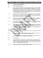
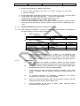
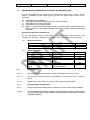
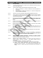
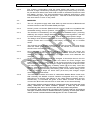
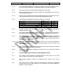
Page 1 of 40
Issue date
RDSO/SPN/
/2014
Version 1.0
POWER SUPPLY ARANGMENT FOR LEVEL CROSSING GATE & INTERMEDIATE
BLOCK WORKING.
VERSION 1.0
Number of Pages….
SPECIFICATION NO. RDSO/SPN/……/2014
SIGNAL DIRECTORATE
RESEARCH, DESIGNS & STANDARDS ORGANISATION
LUCKNOW - 226011
Page 2 of 40
Issue date
RDSO/SPN/
/2014
Version 1.0
DOCUMENT DATA SHEET
Version
Designation
1.0
RDSO/SPN/
/2014
Title of Document
Power Supply Arrangement for Level crossing
gate and Intermediate Block Working.
Authors:
Name: Shri S.N.ram
Designation: Jt. Director / Signal
Approved by:
Name: Shri Mahesh Mangal
Designation: Sr. Executive Director/Signal, RDSO
Abstract
This document defines specification of Power Supply arrangement for level crossing
Gate.
Page 3 of 40
Issue date
RDSO/SPN/
/2014
Version 1.0
DOCUMENT CONTROL SHEET
Designation
Organization
Function
Level
Jt. Director/Signal
RDSO
Member
Prepare
Sr.ED/ED/Signal
RDSO
-
Approval
Page 4 of 40
Issue date
RDSO/SPN/
/2014
Version 1.0
AMENDMENTS
Version
Ver. 1.0
Ver.1.0
Chapter/ Annexes
Amendments
Nil
First issue
RDSO/SPN / /2014
Issue
date
April 2014
Page 5 of 40
Issue date
RDSO/SPN/
/2014
Version 1.0
TABLE OF CONTENTS
Para No.
0.
1.0
2.0
3.0
4.0
5.0
6.0
7.0
8.0
9.0
10.0
Annexure-I
Annexure II
Annexure-lll
Annexure-IV
Item
Page No.
Abbreviations used
6
Foreword
Objective & Scope
General Requirements
Technical Requirements
Performance Requirements
Labeling And Marking
Documentation
Packing
Test and Requirements
Test Procedure
Sampling Procedure for Acceptance Test
LC-IB Power supply IPS configuration for IBS in RE/
Non RE area
Over all dimension of LC-IB Power supply
6
7
Layout of LC-IB Power supply cabinet
Earthing & Bonding arrangement for indoor signalling
equipment
8
10-16
17-28
28-29
29-30
30
30-32
32-35
35
37
38
39
40
Page 6 of 40
Issue date
RDSO/SPN/
/2014
Version 1.0
ABBREVIATIONS USED
Abbreviation
Detail
AVR
Automatic Voltage Regulator
ASM
Assistant Station Master
DSA
Distribution Switching & Alarm Unit
DG Set
Diesel Generator Set
DCDP
DC Distribution Panel
DOD
EI
EMI
IS/IEC
Depth of Discharge
Electronic Interlocking
Electromagnetic Interference
Indian Standard/ International Electrotechnical Commission
LCD
Liquid Crystal Diode
LED
Light Emitting Diode
MTBF
Mean Time Between Failure
MOV
Metal Oxide Varistors
OEM
Original Equipment Manufacturer
PI
Panel Interlocking
PF
Power Factor
PWM
Pulse Width Modulation
RE
Railway Electrification
RFI
Radio Frequency Interference
SMPS
Switch Mode Power Supply
SPD
Surge Protection Devices
VRLA
Valve Regulated Lead Acid
Page 7 of 40
Issue date
RDSO/SPN/
/2014
Version 1.0
GOVERNMENT OF INDIA
MINISTRY OF RAILWAYS
(RDSO)
INDIAN RAILWAY SPECIFICATION
FOR
POWER SUPPLY ARANGMENT FOR LEVEL CROSSING GATE & INTERMEDIATE
BLOCK WORKING
FOR
SIGNALLING INSTALLATIONS ON INDIAN RAILWAYS
(RDSO/SPN/
/2012, Version 1.0)
0.
FOREWORD
0.1
This specification is issued with the fixed serial number followed by the year of
adoption as standard or in case of revision, the year of latest revision.
0.2
This specification is intended chiefly to cover the technical provisions and does
not include the necessary provisions of a contract.
0.3
This specification requires reference to following specifications:
IRS: S 88/2004
IRS:S 93/96(A)
RDSO/SPN/144/2006
RDSO/SPN/165/2012
IS:9000
IRS:S 23
IEC-61643
IEC 61312
IEC 61024
EN 55022
IRS:S 74/89
IRS:S 84/92
EN 50129
Low Maintenance Lead Acid Battery
Valve Regulated Lead Acid Sealed Maintenance Free Stationary Battery
Safety & reliability requirements of electronic signalling equipment.
SMPS based integrated power supply system
Basic environmental testing procedure for electronic and electrical item
Electrical Signalling & Interlocking Equipment.
Surge Protective Devices connected to low-voltage power distribution
systems
Protection against Lightning Electromagnetic Impulse
Protection of structures against Lightning
European Standard for Information Technology Equipment
Voltage Regulator-Ferro Resonant
Solor Photo Voltaic Module.
Railway Application Safety Related Electronic System For Signalling
0.4
Wherever, in this specification, any of the above mentioned specifications is
referred by number only without mentioning the year of issue, the latest issue of
that specification is implied.
1.0
OBJECTIVE & SCOPE
1.1
This specification covers the technical requirements of Power Supply
Arrangement for Level Crossing Gate and Intermediate Block Working with solor
backup (PSA/LC/IB) suitable for wayside signalling installations in RE & Non-RE
areas.
1.2
The PSA/LC/IB system is suitable to work with either Low Maintenance cells as
per IRS: S 88/2004 or with VRLA Maintenance Free cells as per IRS: S
93/96(A).
Page 8 of 40
Issue date
RDSO/SPN/
/2014
Version 1.0
2.0
GENERAL REQUIREMENTS
2.1
The Power Supply Arrangement for Level Crossing Gate and Intermediate Block
Working (PSA/LC/IB) is meant to give continuous supply to both AC & DC
signalling circuits for wayside signalling installations in RE & Non-RE areas.
The Power Supply Arrangement for Level Crossing Gate and Intermediate Block
Working (PSA/LC/IB) consists of the following:
2.1.1
Bi-directional Inverter
The design of Bi-directional Inverter is such that it charges the battery in charger
mode and it converts the battery energy to AC in Inverter mode in the systems
with renewable energy source, where energy is stored in batteries.
2.1.2
DISTRIBUTION/ SUPERVISORY CONTROL /ALARM (DSA)
The System shall have a distribution/ supervisory control / alarm section,
preferably in the upper portion of the rack for termination of battery, load and
AC/DC input & outputs.
2.1.3
GPRS: A GPRS based information system to transmit data corresponding to the
Mains voltage, AC / DC output voltages and battery voltage in addition to the
faults occurring
2.1.4
Automatic voltage regulator (AVR)
The Automatic Voltage Regulator shall be designed in line with
specification IRS: S:74/89 to cater for any load from no load to full load
(from unit power factor to 0.8 lagging) of its rated capacity. The voltage
regulator shall be capable of handling any load, without degrading total
harmonic distortion and regulation.
2.1.5
Solar Photo Voltaic Module (SPV)
The Solar Photo Voltaic Module (SPV) shall be designed in line with
specification IRS: S:84:92 which covers the general and technical requirements
and tests for solar photovoltaic module (for use in Railway S&T installation).
2.1.6
Solar Charge controller
The Solar Charge controller shall be Maximum Power Point Tracking
(MPPT) type. Its rating shall be 25A min (11.0A for inverter & 10A for
battery) and the input voltage range shall be 70V to 150 V minimum.
2.1.7
Transformer rectifier
Transformer-Rectifier set shall be designed in line with RDSO
specification IRS: S:91:93 to covers the general and technical
requirements for use in Railways signalling installations.
Page 9 of 40
2.1.8
Issue date
RDSO/SPN/
/2014
Version 1.0
Transformer
The Transformer shall be designed in line with specification IRS: S:72:88
to cover the general and technical requirements for use in Railway S&T
installation.
2.1.9
2.1.10
Battery Bank
Low Maintenance cells as per IRS: S 88/2004 or with VRLA Maintenance Free
cells as per IRS: S 93/96(A) shall be in line with RDSO specification for use in
railway signalling and telecommunication. The low maintenance battery shall be
of design such that it requires very less topping up in the actual service.
.
Battery racks (MS) for VRLA batteries / wooden rack for low maintenance
batteries, along with its accessories duly approved by purchaser, shall also be
supplied with battery bank. Alternatively, battery may be housed in the Lower
compartment of the IPS rack itself.
2.1.11
The battery is to be installed in a separate room. Low Maintenance batteries are
to be charged at the site by OEM for which power supply shall be arranged by
Railways. A test certificate of initial charging/capacity testing shall be submitted
by OEM to Railways.
2.1.12
OEM shall supply copper cable of suitable dia as per IS: 694 and grade 1100V
for connecting LC-IB power supply to Battery bank (distance to be given by
Railways at the time of indenting) as given below –
a)
For 120AH battery – 10Sq.mm
b)
For 200AH battery – 16 Sq.mm
c)
For 300AH battery – 25 sq.mm
2.1.13
An exhaust fan of 12” size (minimum) shall be supplied for the LC-IB power
supply room by the OEM. The exhaust fan shall run with commercial AC supply.
Railways shall ensure installation & commissioning of the exhaust fan.
2.2
Typical Configurations
2.2.1
Typical configuration of) Power Supply Arrangement for Level Crossing Gate
and Intermediate Block Working (PSA/LC/IB is meant to give continuous supply
to both AC & DC signalling circuits for wayside signalling installations in RE &
Non-RE areas is as per drawing no. SDO/ PSA/LC-IB /001 (Ann-l).
2.2.2
Depending upon the power requirement at the Level Crossing Gate and
Intermediate Block Working, purchaser can give any alternate configuration
using standard modules and ensuring that it meets the overall design of input
and output.
2.3
Indoor Environmental condition
The power supply arrangement for Level Crossing Gate and Intermediate Block
Working is intended for use in most tropical climate in India where the maximum
ambient temperature may reach upto 50ºC with relative humidity reaching upto
95%.
Page 10 of 40
Issue date
RDSO/SPN/
/2014
Version 1.0
3.0
TECHNICAL REQUIREMENTS
3.1
Electrical Requirements
3.1.1
Power Supply Arrangement for Level Crossing Gate and Intermediate
Block Working (PSA/LC/IB) shall be suitable for operation for a nominal
input voltage of 230V AC, 50Hz single phase power supply derived from
Electricity Board or Railway Traction supply or 7.5/10/15 KVA diesel
generator set with AMF control of appropriate quality. The system shall
work satisfactorily with input voltage variation from 150 to 275V AC and
frequency variation from 48Hz to 52 Hz.
3.1.2
It shall be ensured by Railway that the capacity of AC input feeder
installed at the LC Gate/IB Installation is adequate as per the signalling
load catered by system. All the switchgear and cables shall be
adequately rated and shall be of approved makes.
3.1.3
The DG Set used for feeding LC-IB power supply shall be capable of
taking 10% overload for period of one hour during any 12-hour period. It
should be ensured that waveform of DG set is nearly sine wave.
3.1.4
The accidental short circuit at input feeder shall not cause any
interruption to the system. The accidental over voltage shall not cause
any damage to the system.
3.1.5
There shall be an automatic arrangement for disconnecting the mains
within 500 ms to the rack whenever the input voltage is beyond the
specified operating limits with suitable alarm indication. The LC- IB
power supply system shall resume normal working automatically when
the input is restored within the working limits.
3.2
Module replacement time and MTBF
3.2.1
The mean time to replace a faulty module of LC- IB power supply shall be less
than 20 minutes.
3.2.2
The designed MTBF of Bi-directional Inverter, transformer rectifier and
Supervisory control unit shall not be less than 35,000 hours.
3.2.3
The DC fan provided at rack /module level should have MTBF better than
70,000 hours at 40o C. The fan shall be covered with grill.
3.3
Construction
3.3.1
The cabinet shall be within the overall dimensions of 2000-mm max.
Height 750 mm. max. Depth and 750 mm max. Width. The height and
depth of cabinet shall be of equal size. The cabinet shall have min 10mm thick anti-vibrating pad and 75 mm x 5-mm bottom channel as per
sketch no. SDO/ PSA/LC-IB /002 (Ann-ll).
3.3.2
The spares (other than modules used for redundancy) may be placed at
bottom of any rack as per the availability of space.
Page 11 of 40
Issue date
RDSO/SPN/
/2014
Version 1.0
3.3.3
The rack structure and the module frame shall be made up of rigid
framework of steel profiles. The front door, if used, shall be of hinged
type.
The rear panel shall be provided with proper ventilation
arrangement. DC fan shall be provided at rack level for forced cooling.
The operation of such fan shall be continuous.
3.3.4
The rack and module cabinets shall be of robust construction. They shall
be housed in self-supporting cubicles made of cold rolled closed
annealed mild steel sheet of thickness not less than 1.6mm. The rack
shall be adequately ventilated. The ventilating opening shall be less than
3mm size for protection against entry of lizard's etc. The rack shall
conform to IP31 type of protection as specified in table 1 of specification
no. IS 2147-1962.
3.3.5
The rack and the modules shall be treated with zinc chromate primer
followed by electrostatic epoxy powder coating paint finished, passivation
shall be done through seven stage process/sand blasting. Small metal
parts such as nuts, bolts and washers shall be chrome plated. All other
metal parts of the rack shall be plated for protection against corrosion.
3.3.6
The rack and the module cabinets shall be free from sharp edges &
sharp corners.
3.3.7
Provision of doors are optional, the cabinet sides shall have 3mm louvers
covered with wire mesh. However, if the doors are not provided, the sub
system shall have proper enclosures so that any reptile/ insect shall not
enter the LC-IB power supply cabinet. The magnetic latches/handle
shall be provided on the doors.
3.3.8
The racks and the modules shall be designed for easy maintenance and
installation.
3.3.9
Facility shall be provided at the top of the rack to connect external AC
power and lightning arrestors (if provided inside the rack). Where cables
pass through metal panels, suitable rubber grommets shall be provided
to protect cable from damage.
3.3.10
The modules shall be of modular type. The module shall be easily
mounted or removed from the front side of the rack. The module shall be
designed to slide into the rack on a suitable mechanical arrangement.
Suitable arrangement shall be made for pulling out each module
separately. The associated AC input, DC output connection,
control/alarm & interface cable connecting the module shall be
disconnected/installed easily without causing any interruption/damage to
supply & working module.
3.3.11
All materials and workmanship shall be of professional quality to ensure
the MTBF requirements.
3.3.12
The input and output terminals shall be accessible only when the cover
of the cubicle is removed. All the terminals shall be clearly, neatly and
indelibly marked to correspond with the wiring diagram for easy
identification.
Page 12 of 40
Issue date
RDSO/SPN/
/2014
Version 1.0
3.3.13
Input and output connections of Bi-directional inverter, AVR, Transformer
Rectifier and step down transformer shall be made using plug & socket
of adequate rating having power pins with locking arrangement. The
male connector shall be mounted on the device and the female
connector shall be terminated on the cable. Use of terminal blocks for
input and output connections is not accepted.
3.3.14
The finish of steel and panels shall conform to relevant IS specification.
The colour scheme shall be as follows:
a) Rack & doors
b) All modules
Pebble Grey RAL 7032
shall harmoniously match with rack colour
3.3.15
Baffles to be provided at the rack level for forced ventilation of individual
modules.
3.4
Components
3.4.1
Semiconductor and other components used in the equipment shall be of
industrial grade with min. operating temperature range -25oC to + 85oC.
Components shall conform to relevant IS/IEC specification. Resistors and
capacitors shall meet relevant provisions of latest RDSO/SPN/144/2006.
3.4.2
Semi-conductor power devices and other Solid state components used in LC-IB
power supply shall not be operated at more than 50% of the rated maximum
peak voltage and at not more than 50% of the rated maximum average current
under any prevailing conditions. Manufacturer shall submit design details,
components datasheet at the time of type approval.
3.4.3
The manufacturer shall declare the peak reverse voltage, current rating and
working temperature of the rectifier element under ambient conditions, the
number of elements used and the manner of their connection. The peak reverse
voltage rating should not be less than two times the expected reverse voltage
across the devices.
3.4.4
The recommended list of major components and their makes is available
separately.
3.5
Printed Circuit Board
Printed Circuit Board shall generally conform to relevant provisions of latest
RDSO/SPN/144/2006 for safety & reliability requirement of Electronic signalling
equipment.
3.6
Cables & Wiring
3.6.1
All the cables and wires used for wiring and inter connections of modules shall
conform to specification No. IRS: S 76-89/IS 694 of grading 1100V. Aluminium
wires shall not be used. The gauge of wiring shall be such that the current
density does not exceed 3 amperes/mm square.
Page 13 of 40
Issue date
RDSO/SPN/
/2014
Version 1.0
The colour scheme employed for the rack wiring shall be as below:
AC line
AC neutral
Earthing
DC positive
DC negative
Control wiring
: Yellow
: Black
: Green
: Red
: Black
: Grey
3.6.2
All connections shall be made through crimped eyelets and shall be numbered
with PVC cable marker rings/ inkjet printing on cables corresponding to the
numbers/letters shown in the schematic wiring diagram. Soldering shall be used
only where use of crimped eyelets is not possible.
3.6.3
All non-current carrying metal parts shall be bonded together and adequately
earthed.
3.6.4
All wiring shall be neatly secured in position by bunching /strapping & adequately
supported. Where wires pass through any part of metal panel or cover, the hole
through which they pass shall be provided with rubber grommets.
3.6.5
There shall not be any exposed wiring outside the cabinet.
3.7
Transformers and chokes
3.7.1
Transformers and inductors/ chokes used shall be vacuum impregnated
and shall be of natural air-cooled type conforming IS: 6297 (Category 3 &
Grade 2). Class F or higher grade insulating material as per IS:1271 and
polyester enamelled copper winding wire conforming to IS 13730(Pt. 3)
shall be used for winding transformers and inductors/chokes. The gauge
of winding wires shall be such that the current density shall not exceed
2A/sq.mm.
3.7.2
All exposed metal parts of the transformer including laminations shall be
protected against corrosion.
3.8
Potential free contacts
3.8.1
Following potential free contacts shall be provided for extension of alarms at
remote place:
a)
b)
c)
d)
e)
f)
Inverter 1 fail
Inverter 2 fail
Transformer Rectifier fail
Mains fail
Call S & T staff
Battery low (50% Deep discharge)
3.9
Meters
3.91.
Accuracy of 3 ½ D Digital meters used in the LC-IB Power supply cabinet
shall be ± 1%, ± 3 D or better.
Page 14 of 40
Issue date
RDSO/SPN/
/2014
Version 1.0
3.9.2
Meter shall be provided on top of the rack as per Sketch No. SDO/
PSA/LC-IB /layout/003 (Ann-lll).
3.10
Fuses & Connectors
3.10.1
All plug- in connectors shall be non-interchangeable. Connectors as per
IEC 947 shall be provided.
3.10.2
Fuse holder identification shall include details of fuse rating and type.
3.10.3
All power fuses shall conform to specification IS 13703 / IS 9224.
3.11
Noise and Vibration
3.11.1
Fully equipped rack at full load shall not contribute more than 15dB
(weighted) to the ambient noise level taken as 45dBA. It shall be
measured at a distance of 1 meter from the unit and 1.25 meter above
the floor level in the full audio range upto 3.4 KHz. The correction factor
for total noise when the ambient noise level is more than 45dBA shall be
as given below:
Ambient Noise
(dBA)
Correction Factor
(dB)
Ambient noise
(dBA)
Correction
Factor (dB)
45
46
47
48
49
50
51
52
0
0.18
0.39
0.61
0.86
1.12
1.41
1.73
53
54
55
56
57
58
59
60
2.07
2.43
2.82
3.25
3.69
4.17
4.68
5.21
Note: The correction factor shall be added to the limit of 60dBA to arrive
at the limit when the ambient is greater than 45dBA.
3.11.2
The LC- IB power supply sub-systems shall be suitably screened and
immune to any kind of EMI interference. The sub-system shall not
produce any hum in the peripheral devices.
3.12
Lightning & Surge Protection
3.12.1
Stage 1 Protection (at the entry point of input 230V AC supply in the
power/ equipment room)
(a)
The Stage 1 protection shall consist of coordinated Class I / B & II / C type SPDs
at the entry point of input 230V AC supply in Power /Equipment room in TT
configuration in a separate wall mountable box. The Class I / B SPD shall be
provided between Line to Neutral & Neutral to Earth. They shall be spark gap
type voltage switching device and tested as per IEC 61643 with the following
characteristics and featuresS
N
Parameters
1
2
Nominal Voltage (U0)
Maximum continuous operating voltage (Uc)
Limits
Between Line &
Between
Neutral
Neutral & Earth
230V
≥ 255V
230V
≥ 255V
Page 15 of 40
Issue date
3
4
5
6
7
Lightning Impulse current 10/350μs (Imp)
Response time (Tr)
Voltage protection level (Up)
Short circuit withstand and follow up
current extinguishing capacity without
back up fuse (Isc & Ifi)
Temporary Over Voltage (UT)
8
Operating temperature / RH
9
10
11
12
Mounted on
Indication
Pluggability
Potential free contact for remote
monitoring
Encapsulation
Degree of protection
Housing
13
14
15
(b)
RDSO/SPN/
/2014
Version 1.0
≥ 25KA
≤ 100 ñs
≤ 2.5KV
≥3KA
≥ 50KA
≤ 100 ñs
≤ 2.5KV
≥100A
334V min. for
05 secs.
- 25oC to
+80oC/ 95%
din rail
Mandatory
Optional
Optional
1200V min.
for 200ms
- 25oC to
+80oC/ 95%
din rail
Optional
Optional
Optional
Encapsulated
IP20
Fire retardant
as per UL 94
Encapsulated
IP20
Fire retardant
as per UL 94
The Class I / B SPD will be followed by Class II / C SPD adjacent to it and
connected between Line & Neutral. The device shall be a single compact
varistor of proper rating and in no case a number of varistors shall be provided in
parallel. It shall be voltage clamping device, thermal disconnecting type and shall
be tested as per IEC 61643 with the following characteristics and featuresSN
Parameters
1
2
3
4
5
6
Nominal Voltage (U0)
Maximum continuous operating voltage (Uc)
Nominal discharge current 8/20μs (In)
Maximum discharge current 8/20μs (Imax)
Response time (Tr)
Voltage protection level (Up)
7
8
10
11
12
13
14
Operating temperature / RH
Mounted on
Indication
Pluggability
Potential free contact for remote monitoring
Degree of protection
Housing
Limits (between Line &
neutral)
230V
≥ 300V
≥ 10KA
≥ 40KA
≤ 25 ñs
≤ 1.5 KV
- 25oC to +80oC/ 95%
Din rail
Mandatory
Mandatory
Mandatory
IP20
Fire retardant as per UL
94
(c)
Class I /B and class II /C SPDs of Stage I shall be so coordinated that the
voltage protection level of the coordinated devices is ≤ 1.5 KV. As such, these
devices shall be from the same manufacturer and necessary test certificate in
this regard shall be submitted by the manufacturer/ supplier.
3.12.3
Stage 2 protection (at the output side inside the distribution panel)
The Stage 2 protection shall consist of Class II / C type SPDs for ≥24V-110V
AC/DC supplies at the output side inside the rack of IPS. The Class II / C type
SPD shall be a single compact varistor of proper rating and in no case a number
of varistors shall be provided in parallel. It shall be voltage clamping device and
thermal disconnecting type. These shall be provided at Solar MPPT charger,
Page 16 of 40
Issue date
RDSO/SPN/
/2014
Version 1.0
Inverter, Transformer Rectifier and Signal transformer output. They shall be
tested as per IEC 61643 with the following characteristics and featuresSN
Parameters
1
2
Nominal Voltage (U0)
Maximum continuous
operating voltage (Uc)
Nominal
discharge
current 8/20μs (In)
Maximum
discharge
current 8/20μs (Imax)
Response time (Tr)
Voltage protection level
(Up)
Operating temperature /
RH
Mounted on
Indication
Pluggability
Potential free contact for
remote monitoring
Degree of protection
Housing
3
4
5
6
7
8
10
11
12
13
14
Limits (between L1 & L2, L1 & E , L2 & E)
60V-110V AC/DC
≥ 150 (AC)
≥ 200 (DC)
≥ 10KA
24V-60V AC/DC
≥ 75 (AC)
≥ 100 (DC)
≥ 10KA
≥ 40KA
≥ 40KA
≤ 25 ñs
≤ 1.0 KV
≤ 25 ñs
≤ 0.5 KV
- 25oC to +80oC/
95%
Din rail
Mandatory
Mandatory
Mandatory
- 25oC to +80oC/
95%
Din rail
Mandatory
Mandatory
Mandatory
IP20
Fire retardant as per
UL 94
IP20
Fire retardant as per
UL 94
3.12.4
Length of all cable connection from SPDs to earth equi-potential busbar shall be
kept less than 0.5mtrs. For this, a sub earth equi-potential busbar shall be
installed at approx. 20cm from the SPD box. The details of connection of SPDs
for Stage 1, & 2 of a typical installation with LC-IB power supply is enclosed as
Annexure-IV.
3.12.5
Batch test report of OEM should be submitted by the manufacturer
/supplier of Lightning & Surge protection devices to the LC-IB Power
supply manufacturer at the time of supply of these devices. Copy of the
same shall be submitted by the LC-IB Power supply manufacturer to
RDSO at the time of acceptance test of system.
3.13
Earthing
3.13.1
The LC-IB Power supply systems and its individual modules shall have
earth terminals and shall be properly earthed to the cabinet.
3.13.2
Zonal Railways shall provide earthing arrangement in conformity to Code
of practice for earthing and Bonding RDSO/SPN/197/2008 as per details
at Annexure-V.
3.14
Installation & Commissioning
Installation shall be done by OEM if specified by the purchaser. However,
commissioning of LC-IB Power supply system shall be done by the OEM only.
OEM shall issue a certificate of fitness of installation before commissioning. For
this, Zonal Railways and OEM shall ensure the compliance to Precommissioning checklist issued by RDSO.
Page 17 of 40
Issue date
RDSO/SPN/
/2014
Version 1.0
4.0
PERFORMANCE REQUIREMENTS
4.1
SOLAR MPPT CHARG CONTROLLER
4.1.1
4.1.2
Solar Charge controller shall be Maximum Power Point Tracking (MPPT)
type.
Its rating shall be 25A min( 11.0A for inverter & 10A for battery).
4.1.3
The input voltage range shall be 70V to 150 V minimum
4.1.4
Resettable Fuses shall be provided, wherever appropriate, to protect the
module against failure of control / sensing circuit.
4.1.5
The design shall have suitable time delay / hysteresis to avoid hunting
during switching ON and OFF of the system.
4.1.6
Screen-printed procedure for adjustment of battery current limit and other
adjustment required to be done in the field shall be prominently visible for
ready reference of maintenance staff.
4.1.7
The DC volt/Ampere digital meter of 3 ½ digit with LCD/LED
alphanumeric display having 12mm height shall be provided on the front
side of the charger to read array voltage, load /charging/ discharge
current.
4.1. 8
The efficiency of Solar Charge controller from 70V to 150 V at full load shall be
>90% with resistive load.
4.1. 9
DC Over Voltage Protection: In case output DC voltage exceeds 2.37V/2.5V per
cell respectively for VRLA/ low maintenance battery, the over voltage protection
shall operate & shut off the charger. This shut off can be restored automatically
as soon as fault removed.
4.1. 10
The circuit design shall ensure protection against the discharge of the battery
through charger. In any case, the discharge current i.e. reverse leakage current,
shall not be more than 100 mA .
4.1. 11
The over voltage protection circuit failure shall not cause any safety hazard.
4.1.12
Solar Photovoltaic (SPV) Module shall be purchased from RDSO
approved vendors in line with IRS:S:84/92 duly inspected by RDSO
inspection wing.
4.1.12.1
Requirement of Solar Panel Solar (Typical calculation)
a.
b.
c.
d.
e.
f.
Load on 48V DC bus = 489 (Load on DC bus )/0.85 = 575W
Taking 15% extra for future load demand = 600W
The power rating of PV panel to supply the 600W
=
(600*1.15)/.94=731W
(Considering 15% extra to cater for solar loss due to fixed installation/sun
tracking & cable loss & 94% MPPT efficiency)
PV panel power considering watt hour efficiency of battery 85%=
731/.85= 860W
Total no of 70W PV panel module 860/70= 12 Nos.
For 70W module Voc=21V, Vmp =17.2V, Imp = 4.3A
Page 18 of 40
Issue date
RDSO/SPN/
/2014
Version 1.0
g. Panel Configuration for 860W solar power
6 nos. in series (string) so Voc = 21V * 6= 126V & Vmp= 17.2*6=102V
2 string in parallel.
h. Total usable WH generated per day per hour= 860*0.94*.85/1.15= 597.51WH
i. Total usable WH generated per day = 597.51*5= 2987.5WH
(Considering average Solar Insolation period as 5 hrs)
j. Usable AH generated per day = 2987.5/48= 62AH
So 62 AH is pumped to battery every day which is sufficient to give 4-5 hour
back up. Since the battery used is 100AH .its 62AH can’t be withdrawn per
day.
4.1.13
Alarms & Indication of Solar Charge controller
4.1.13.1 The following indications, controls & measuring points shall be provided on
the front panel of Solar Charge controller
A)
Status Indication:
Description
INPUT available
B)
Nomenclature
MAINS
Indication
Amber
Alarm Indication:
Description
c) DC output fuse fail
d) CH Overload/ short circuit
e) Reverse Polarity Indication
Nomenclature
Indication
OUTPUT FAIL
OVERLOAD / SHORT
CIRCUIT
BATTERY REVERSE
Red
Red
Red
Note: “Provision shall be made for stopping the audio alarm with a non-locking
push button.
C)
4.1.14
Digital Volmeter/ammeter of 3 ½ digit, ± 1% Accuracy with
LCD/LED alphanumeric display having 12mm numerical display
height shall be provided on the front panel of the Solar Charge
controller for measuring input & output voltage and output current.
Terminations
a)
The DC input and output connection should be taken through
irreversible plug and socket having power pins with locking arrangement.
b)
The output of Solar Charge controller in the positive lead shall be taken
through the HRC fuse of 1.5 times of rated capacity.
c)
In all cases, the male connector shall be mounted in the Solar
Charge controller and the female connector shall terminate the
cable.
d)
To prevent hazards or damaging conditions,
components shall be non-interchangeable.
e)
All the connections between DSA unit and Solar Charge controller
shall be through proper rated cables only.
f)
Circuit breakers at the input of each FRBC shall be easily
accessible and rated to 25A .
all
plug-in
Page 19 of 40
4.2
Issue date
RDSO/SPN/
/2014
Version 1.0
DISTRIBUTION/ SUPERVISORY CONTROL /ALARM (DSA) UNIT
The LC-IB Power supply shall have a distribution/ supervisory control / alarm
section, preferably in the upper portion of the rack which shall consist of the
followinga)
b)
c)
d)
e)
Termination for the batteries.
Termination for the load (Inverters & Trans former rectifiers).
Termination for AC input to the rack.
Termination for DC to solar charger.
GPRS: A GPRS based information system to transmit data corresponding to the
Mains voltage, AC / DC output voltages and battery voltage in addition to the faults
occurring.
Alarms & Indication of DSA Unit
All the indications shall be derived on a microprocessor based control and
supervisory unit and displayed on an LED / LCD type alphanumeric display.
(a)
Status Indication:
Description
a) Mains available
b) Mains fail
(b)
Nomenclature
MAINS
MAINS FAIL
Indication
Amber
Red
Alarm Indication:
Description
a) Load voltage high
b) Mains out of range
c) System overload
d) Mains ‘on’/battery
discharging
f) Battery / load fuse fail
h) Battery disconnected from
circuit
Nomenclature
OUTPUT VOLT HIGH
MAINS VOLT LOW /HIGH
OVERLOAD
MAINS ON & BATTERY ON
LOAD
FUSE FAIL
BATTERY
DISCONNECTED
Indication
Red
Red
Red
Red
Red
Red
4.2.1
Accessibility
4.2.1.1
The termination points shall be easily accessible from front or rear.
4.2.1.2
AC and DC terminals shall be separated by physical barriers to ensure
safety.
4.2.1.3
All the terminals except AC earth shall be electrically isolated.
4.2.2
AC termination arrangement
4.2.2.1
The input terminals shall be clearly marked as L & N for mains supply voltages.
4.2.2.2
AC input termination shall be suitably protected against accidental touch/contact
with the working staff for their protection and shall also have clear and prominent
‘DANGER’ Marking.
Page 20 of 40
Issue date
RDSO/SPN/
/2014
Version 1.0
4.2.3
DC terminations
4.2.3.1
Connection between the solar charger and DC distributions shall be through a
proper rated lugged cable.
4.2.3.2
The DC output to battery and load shall be through bus bar or cable.
a)
b)
Battery fuse shall be of 1.5 times of maximum current that passes to /
from battery.
Fuse at the O/P of FRBC rack shall be of 1.5 times the designed O/P
current required for the system.
4.2.3.4
All the AC, DC and Control/Alarm cabling shall be supplied with the rack.
4.2.3.5
All DC positive & negative terminals shall be clearly marked and shall be suitable
for minimum 10 sq. mm cable size. All conductors shall be properly rated to
prevent excessive heating.
4.2.4
All the above indications may also be derived on a microprocessor based control
and supervisory unit and may be displayed on an LED / LCD type alphanumeric
display.
4.2.4.1
All alarm circuits shall be provided with suitable delay to ensure that they do not
operate with transients.
4.2.4.2
All the protection/alarms shall be within tolerance of ± 0.012V per cell for voltage
and ±1% in case of current.
4.2.4.3
Every alarm condition shall be accompanied with audio alarm with auto cut off
after 120 seconds. Provision shall be made for stopping the audio alarm with a
push button switch.
4.2.4.4
In case of any kind of failure in DSA unit, the unit shall switch over to safe mode.
4.2.5
Battery Health Monitoring
4.2.5.1
Battery Current Limiting Circuit: To ensure the availability of required load
connected and safety of the battery, the battery charging current limit shall be
provided @ 10% of battery AH capacity as per requirement..
4.2.5.2
Battery Reverse Polarity Protection: Protection for battery reverse
polarity shall be provided in the system. The reverse polarity indication
shall be provided near the battery terminal.
4.2.5.3
Battery under voltage isolation: The system shall have provision for
battery isolation using DC contactor. The battery isolation shall be
effective at
i) For VRLA Battery: 1.80V/cell (± 0.012V/cell)
ii) For low maintenance lead acid battery: 1.85V/cell (± 0.012V/cell)
iii) Battery under voltage adjustment shall be provided inside the
switching control unit/ DSA . This setting shall be adjustable from
1.80 to 2.0V/cell. Battery shall get reconnected after restoration of
supply.
Page 21 of 40
Issue date
RDSO/SPN/
/2014
Version 1.0
4.2.6
The system configuration shall be made either with cable or bus bar.
Bus bar of high conductivity electrolytic copper strips with purity of 99.9%
as per BIS 613 latest issue and shall be able to withstand maximum load
and battery current. The bus bar/cable sizes shall be sufficient to cater
current density upto 2 Amps per sq.mm. The size of bus bar shall not be
less than 25mm x 5mm in any case.
4.3
INVERTER
4.3.1
The LC –IB power supply with solar back up shall consist of Bidirectional
Inverter based on the sinusoidal PWM principal.
4.3.2
DC/AC power converters (Bidirectional Inverter) shall be compatible with
renewable energy source systems, where energy is stored in batteries.
4.3.3
The inverter is controlled by two minimum time feedback loops, providing
relatively low output voltage distortion and good load regulation with the
inverter efficiency greater than 85% over a wide output power range.
4.3.4
The design of Bi-directional Inverter is such that it charges the battery in
charger mode and it converters the battery energy to AC in Inverter
mode.
4.3.5
The Inverter circuit should continuously monitor the 230 V AC bus and in
case the same goes above or below the set values, the Inverter mode
should come on within 40 ms.
4.3.6
Once this 230 V BUS voltage resumes to within the set range, the
Inverter mode would be off and converter mode would be ON thus
charging the battery and keeping it in Float mode once batteries are
charged.
4.3.7
In AC-DC mode when batteries are charged, it should be done in CC/CV
mode whereby on energization the unit starts as Float charger and
battery path current is monitored. If it is found more than 10% of the Max
Boost current of battery, the charger output changes over to Boost mode
and constant current charging of battery starts (@ C/10 rate). Once the
Battery voltage reaches the set boost voltage level, it turns to Constant
Voltage (CV) mode whereby the battery path current starts falling. Once
it falls to within 2 Amps for some time (5-45 sec) the charger output
reverts back to Float mode.
4.3.8
Two identical Inverters are used In redundant Master-Slave mode such
that normally the Master Inverter remains energized and only when it
fails (due to its control card failure or any other failure including its own
transformer), a command be given to the Slave Inverter to start and
connect AC BUS with transfer time to less than 40 ms automatically.
4.3.9
The inverter shall be protected against overload and short circuit with auto reset
facility. Whenever the failure condition persists, it shall trip and restart
automatically after about 10-20 seconds. But if the problem still persists,
the protection shall permanently get latched and inverter shall not be switched
ON again unless the fault is cleared followed by pressing of reset push button
switch. Inverter overload indication shall appear at 110% of rated load.
Page 22 of 40
Issue date
RDSO/SPN/
/2014
Version 1.0
4.3.10
Inverter shall be designed for continuous operation for an input voltage of 44V to
56 V at a nominal of 48V DC, and shall be rated for an output of 230V AC.
4.3.11
The input & output of inverter shall be isolated from each other.
4.3.12
Each inverter shall be provided with suitable DC MCCB/MCB at the input for
connecting the DC input.
4.3.13
The DC fan, if provided, should have MTBF better than 70,000 hours at 40ºC.
The switching ON & OFF the fan shall be with temperature control.
4.3.14
The following LED indications shall be provided on front panel:
Description
Nomenclature
Indication
a) Input ON
b) Output OK
c) Inverter fail
d) Inverter ‘ON load'
e) Fan fail indication(In case of forced cooling)
Input DC ON
OUTPUT
INVERTER FAIL
ON LOAD
FAN FAIL
Amber
Green
Red
Green
Red
4.3.15
Voltage overshoot and under-shoot in the first cycle for complete load shut off
shall be restricted to 20%.
4.3.16
The output voltage waveform shall be sine wave. Total harmonic distortion of
the output shall not exceed 4% under any condition specified in clauses 4.3.10.
4.3.17
The inverter shall be capable of delivering 125% of rated full load for a period of
24 hours. It should be capable of delivering 200% of the rated full load for a
period of 300 ms in order to cater for the high in-rush current at the time of
switching ‘ON’ of the inverter.
4.3.18
The output of inverters shall be regulated to 230V ± 1% for an input variation of
44V to 56 V DC and for a simultaneous load variation of 25% to 100% of its
rated capacity.
4.3.19
The overall watt efficiency of the inverter shall not be less than 85% at full load
for the entire input range of 44V to 56V DC.
4.3.20
The unit shall be capable to withstand 20 cycles / hrs of 1.5 minute each ON and
OFF at rated load.
4.4
Ferro-Resonant Type Automatic Voltage Regulator (AVR)
4.4.1
The design of the Automatic Voltage Regulator shall cater for any load
from no load to full load of its rated capacity.
4.4.2
The voltage regulator shall be completely static without any moving
parts.
4.4.3
The AVR shall be suitably screened so that other electronic equipment
placed side by side of the regulator is not affected by the electromagnetic
radiation of the regulator.
Page 23 of 40
Issue date
RDSO/SPN/
/2014
Version 1.0
4.4.4
The voltage regulator shall be of natural air-cooled type and shall be
suitable for indoor use in the cabins where maximum ambient
temperature can reach upto 50ºC.
4.4.5
The regulator shall function satisfactorily under shock and vibration
conditions encountered by the side of railway track. Main transformer
shall be mounted on anti vibrating padding.
4.4.6
AC Metal Can Capacitors of 600V rating of approved type with in-built
wire shall only be used. The capacitors shall be mounted at a minimum
distance of 2" away from the main transformer’s top plate with metal
partition in between the transformer and capacitor. This partition shall be
of heat insulating material as the purpose is to protect capacitors from
heat.
4.4.7
The output tappings at 0, 220, 230& 240V shall be provided.
4.4.8
Transformers and inductors/ chokes used shall be vacuum impregnated
and shall be of natural air-cooled type conforming IS: 6297 (Category 3 &
Grade 2). Class F or higher grade insulating material as per IS:1271 and
polyester enameled copper winding wire conforming to IS 13730(Pt. 3)
shall be used for winding transformers and inductors/chokes. The gauge
of winding wires shall be such that the current density shall not exceed
1.6A/sq.mm.
4.4.9
Two pole ON/OFF rotary switch conforming to IS: 4064 (Pt.I) shall be
provided for input to the regulator.
4.4.10
A LED to indicate that the unit is ‘ON’ shall be provided on the front
panel.
4.4.11
The output voltage shall remain at the nominal value of 230V± 1% at all
the loads varying from 25% load to full load keeping the input voltage
constant at 230V 50Hz.
4.4.12
The regulator shall work satisfactorily within supply frequency of 50Hz ±
2.5 Hz. The value of output voltage at rated load with an input of 230V at
50 Hz shall be taken as the reference output voltage for individual unit.
When input frequency is varied from 47.5 Hz to 52.5 Hz, keeping the
input voltage constant, the output voltage of the regulator unit shall be
maintained within ± 3% of the reference output voltage for ± 1 Hz
variation and within ±6% for ± 2 Hz frequency variation.
4.4.13
The regulator shall work satisfactorily within a range of 160V to 270V
input at 50Hz mains supply. The output voltage shall be maintained
within 230V ± 1% when the unit is connected to rated load.
4.4.14
The response time of regulator for sudden changes of 50 V AC input
voltage or load variation from 25% to 75% of the rated load shall be such
that the output voltage should settle at 230V ± 1% within 3 cycles/60m
seconds.
Page 24 of 40
Issue date
RDSO/SPN/
/2014
Version 1.0
4.4.15
The no load current shall not be more than 25% of the rated input current
and the no load power shall not be more than 10% of the rated output
power at nominal input voltage of 230V at 50Hz.
4.4.16
The overall watt efficiency shall not be less than 85%.
4.4.17
The total harmonic distortion measured at the output of the regulator
shall not exceed 8% under any working conditions specified in Clauses
4.4.11, 4.4.12 & 4.4.13.
4.4.18
The voltage regulator shall be capable of handling any load from unit
power factor to 0.8 lagging, without degrading total harmonic distortion
and regulation.
4.4.19
When continuously operating at full load at any ambient condition
specified in clause 2.3, the regulator shall withstand short-circuit on
output side for one hour without any damage or deterioration to the
regulator or any of its components.
4.4.20
The resonant voltage across the capacitor bank shall not exceed 480V at
all input voltage and frequency conditions i.e 160-270V & 47.5Hz to
52.5Hz at no load.
4.4.21
Suitable surge voltage protection shall be incorporated in the circuit,
preferably with high isolation between primary and secondary sides.
4.4.22
Ferro resonant voltage regulator for Signal load shall always be in
‘switched on’ condition and shall supply the load within 60 ms in case of
any failure in Inverter/s and or inverter changeover arrangement. As
soon as any one of Inverter becomes healthy, the load shall be
automatically transferred back to inverter within 60ms.
4.4.23
In case of failure of contactor, provision shall be made for manual bypass
of Static switch through a manual change over switch.
4.5
TRANSFORMER RECTFIER
4.5.1
The Transformer Rectifier covered under this specification shall work
satisfactorily in line with IRS: S: 91/2014.
4.5.2
Transformer Rectifier shall be connected in the following order:
i)
ii)
iii)
iv)
v)
vi)
4.5.3
Relay internal
Relay external
Track Circuit
LED signal
Electric Lifting Barrier
Panel indication
All components dissipating 3W or more power shall be mounted so that the
component body is not in contact with the unit unless a clamp, heat sink or other
means are used for proper heat dissipation.
Page 25 of 40
Issue date
RDSO/SPN/
/2014
Version 1.0
4.5.4
Transformer Rectifier shall be provided with a proper plug in arrangement for AC
input & output.. A toggle switch / push button switch shall be provided for
switching ON/OFF the unit.
4.5.5
The Transformer Rectifier shall be provided with means for protection and visual
indication on front panel for the following:
Description
i) Input Power ON indication
ii) Transformer Rectifier output OK
iii) Transformer Rectifier fail
Nomenclature
Indication
INPUT
OUTPUT
FAIL
Amber
Green
Red
4.5.6
The transformer rectifier shall be rated for 230 AC single phase input voltage at a
frequency of 50Hz ±2Hz.
4.5.7
The nominal output voltage is 24 DC and current ratings are 5 and 10 Amps.
4.5.7
The DC output of the unit shall be smoothened by use of a suitable filter such
that the RMS ripple content of the output voltage when delivering the rated output
current through a resistive load, measured by an oscilloscope/ true r.m.s.
multimeter shall not be more than 5%.
4.5.7.1
The overall watt efficiency shall not be less than 75% for rectifiers above 500VA
capacity.
4.5.8
The no load input current of the transformer-rectifier unit shall be less than 10% of
the rated input current.
4.5.9
No load to full load voltage regulation of the transformer when measured with the
highest voltage tapping on secondary side loaded to the rated current shall be <
10% for < 100VA, < 5 % for 100VA & above.
4.5.10
The 'ON LOAD' output tap voltages shall be within +/- 2.5% of the nominal output
voltages.
4.5.11
The output voltage regulation of transformer rectifier unit at no load to full load shall
be less than 20% .
4.5.12
The output must be isolated from input.
4.6
Step-down Transformer
4.6.1
Terminals & associated screws shall be of nickel-plated brass, and shall be of the
top screw pillar type, securely fixed.
4.6.2
The transformer shall be of double wound type and shall be designed for an
input voltage of 230V ± 2%, 50Hz and ratings shall be 500 VA & 1000 VA.
4.6.3
The transformer shall have separate input and output windings.
4.6.4
The primary of the transformer is 230V. The secondary winding shall have tappings
at 0, 100, 110, 120 & 130 volts at no load.
Page 26 of 40
Issue date
RDSO/SPN/
/2014
Version 1.0
4.6.5
The gauge of winding wires shall be such that current density does not exceed
2A/mm sq.
4.6.6
A rotary switch of 10A or above shall be provided for switching ON/OFF the
transformer.
4.6.7
The size of the core shall be as small as possible commensurate with the
electrical characteristics required by this specification.
4.6.8
The core of the transformer shall be such that its Electro-magnetic property will
not be affected due to ageing.
4.6.9
The body of the core is required to be earthed and one earth terminal shall be
provided for this purpose. Suitable marking shall be made near the earth
terminal.
4.6.10
The efficiency of the transformer at rated load with nominal input shall not be
less than 90%.
4.6.11
The appropriate voltage shall be legibly & indelibly engraved near the input and
output terminals.
4.6.12
An HRC fuse of appropriate rating shall be provided at the input of transformer.
4.6.13
The following LED indications shall be provided on the front panel:
Description
a) Input ON
b) Output ON
c) Tx. Fail
Nomenclature
INPUT
OUTPUT
FAIL
Indication
Amber
Green
Red
4.6.14
230V AC at 50 Hz shall be applied on primary side between terminals ‘0’ and
‘230V’ and the voltages across different tappings on the secondary side shall be
measured, which shall be within ± 1.5% of the nominal value.
4.6.15
The open circuit secondary voltage and the primary no load current of the
transformer shall be measured with the primary winding connected to 230V,
50Hz supply and the secondary winding open circuited. The open circuit
secondary voltage at different tappings of the secondary windings shall be within
± 1.5% of the nominal values. The primary no load current shall not exceed
10% of the rated full load primary current for all transformers.
4.6.16
The percentage voltage regulation shall not be more than 5%.
4.6.17
Induced High Voltage Test: - The transformer shall withstand without break
down, when 440 volt 100 Hz AC is applied to the primary winding, with
secondary winding open-circuited. The voltage shall be raised from one third of
the maximum value to maximum value as rapidly as is consistent with accurate
reading of the indicating instrument. The full test voltage shall be maintained for
one minute and shall then be reduced to the one third of the value before being
switched off. At the end of the test the transformer shall be tested for the
following:
Page 27 of 40
Issue date
RDSO/SPN/
/2014
Version 1.0
a) Insulation resistance (Clause 9.2)
b) Open circuit test (Clause 4.6.15)
4.6.18
The transformer shall withstand without any damage short circuit of
secondary windings momentarily when primary is fed with 230V AC at
terminals 0V and 230V. The test shall be carried out after bypassing the
fuse.
4.6.19
Applied high voltage test as per clause 9.3 shall be repeated after short
circuit test.
4.7
Requirements of LC-IB solar charge controller Panel
4.7.1
The following 3 ½ D digital meters with LED/ LCD display having 12mm
numerical display shall be provided on top of the charger panel. The
selector switch for meter shall not be at a height of more than 1800 mm
from the ground.
a)
b)
c)
d)
AC Volt meter
AC Ammeter
DC Voltmeter
DC Ammeter
0-300V
0-50A
0-200V
0-50A
for AC input voltage
for AC input current
for charger output voltage
for charger output current/charge/
Discharge current.
A selector switch shall be provided for reading Total/ Charge / Discharge
current.
4.7.2
The DC meters shall work even when the AC supply is not available.
4.7.3
AC digital volt meter shall be provided with extendable cords for
measurements of output voltages of the following:
a)
b)
c)
d)
Inverter 1
Inverter 2
AVR
Tx. (ELB)
4.7.4
Output of Inverter, step down transformer & AVR shall be brought to one
place at the rear of the cabinet. 30 Amp capacity TB type terminal
capable of termination of 10-sq. mm cable shall be provided. Proper
identification marking shall be provided on/near the terminals.
4.7.5
All the above indications/measurements may be derived on a
microprocessor based control and supervisory unit and may be displayed
on an LED / LCD type alphanumeric display.
4.8
Status Monitoring Panel
4.8.1
Status monitoring panel shall be installed in the room of Gateman on duty at LC
gate. The panel shall have following LED indications and alarms with resetting
switch:
Page 28 of 40
Issue date
Instruction
RDSO/SPN/
Condition
LED Ind.
A
Run Gen set
50% DOD
RED
B
Emergency
start generator
System shut
down
60% DOD
RED
70% DOD
RED
D
Call S & T staff
Equipment fault
RED
E
Stop Gen Set
FRBC change over
to float mode
C
GREEN
/2014
Version 1.0
Remark
Audio / visual alarm. Alarm can be
acknowledged for audio cut off.
-doSignal feed cut off and all DC-DC
converters to work. Audio alarm will
continue till Generator is started.
Failure of any module or in case battery
gets disconnected from circuit will give
the alarm in panel. Alarm can be
acknowledged for audio cut-off.
Audio /Visual alarm
Audio alarm in case of A, B & C shall be of one type of tone and there shall be
different tone for the case of D & E cases.
4.8.2
In A, B & C conditions, the visual LED indication will remain lit until fault is
cleared or the DG set is started and battery is charged upto 110V i.e. 2V/cell as
the case may be until reset push button is pressed. In case of D condition, if fault
is not cleared, the LED will continue to glow, even if reset push button is
pressed.
4.9
INDENTING DESCRIPTION / INFORMATION TO BE SUPPLIED BY
THE PURCHASER:
Indenting description / information to be supplied by the Purchaser for
the LC-IB power supply system configuration covered under clause 2.2.1
is as under:
Details
1
2
3
4
5
6
7
Remarks
Configuration/ Applicable drawing The configuration is as per details
No.
given
in
clause
2.2.1
or
configuration specified by the
purchaser using standard modules
Type of Battery
Low Maintenance or VRLA
Type of Internal & External relays
24V
Type of the track circuit
Type of the ELB provided at LC
Distance between LC gate Room
& ASM Panel (in meters)
Whether installation is to be done
by OEM
5.0
LABELLING AND MARKING
5.1
Each electrical/solid state component should be possible to be located by the
layout/circuit drawing. The wiring shall be clearly and permanently identified with
a designation or a colour code, which corresponds to the equipment circuit
diagram. Where non-standard colours are used, cable functions shall be clearly
and permanently labelled at both ends.
5.2
A screen printed cabling / wiring diagram shall be placed on the inside of the
front door or any other convenient place for ready reference of maintenance
staff.
Page 29 of 40
Issue date
RDSO/SPN/
/2014
Version 1.0
5.3
Screen-printed Do’s & Don’ts, adjustment procedures and operating instructions
shall be provided at convenient place on front panel of the LC-IB panel. One
laminated block diagram shall also be provided at convenient place inside the
cabinet.
5.4
The layout of the components and wiring shall be such that all parts are easily
accessible for inspection, repairs and replacement.
5.5
All markings shall be legible and durable. Where the marking is by use of labels,
they shall be metallic or screen-printed. These shall be firmly struck and shall
not be capable of being removed by hand easily. They shall be placed in the
vicinity of the components to which they refer.
5.6
The cubicle shall be identified with the following appropriate name plates/labels:
“LC-IB POWER SUPPLY PANEL”
5.7
The placement for particular module in respective rack shall be clearly
marked with its application for the purpose of appropriate replacement.
5.9
Every LC-IB POWER SUPPLY PANEL shall be provided with a rating
plate fixed outside at a conspicuous place in the cubicle. It shall be
clearly and indelibly etched, engraved or screen printed and shall show
the following minimum information:
a)
b)
c)
d)
e)
Name and trade mark of the manufacturer
Specification No.
Nominal AC input voltage and frequency
Serial number and year of manufacturing.
Version number as per RDSO/SPN/144/2006.
5.10
All input and output terminals shall be clearly identified by using proper
name tags/labels.
6.0
DOCUMENTATION
6.1
Two copies of the user's instruction manual shall be supplied along with
each unit. The version number shall be clearly indicated on front cover.
The manual shall include detailed design of the LC-IB POWER SUPPLY
/modules, dimensional layout drawings, schematic diagrams, and
detailed interconnecting drawing of all sub systems. Traceability of
interconnection between sub systems shall be ensured. Details on initial
checks on receipt at site, testing and adjustment procedures, installation
and commissioning procedures, maintenance procedures and detailed
trouble shooting chart shall be covered in the manual. All the details in
the manual shall be in simple language with trouble shooting explained
through suitable pictures/ photographs in step by step manner so that it
is well understood by the maintenance staff.
6.2
The instruction manual is to be prepared using good quality paper with
clear crisp printing. All the drawings in clear printing shall be attached to
the handbook binding. One set of flow chart drawings necessary for
trouble shooting shall be provided with lamination with each manual.
Page 30 of 40
Issue date
RDSO/SPN/
/2014
Version 1.0
The handbook shall have a thick polythene sheet cover with plastic
winding or comb winding.
6.3
The manufacturer shall submit certificate of the equipment for its
satisfactory performance for 24 months from the date of commissioning.
During the warranty period, any defect should be repaired free of cost.
6.4
The joint pre-commissioning checklist and post commissioning load
measurements shall be a part of instruction manual. The system shall be
commissioned, as per specification and representatives of manufacturer
and purchaser/railways shall sign this jointly.
7.0
PACKING
7.1
Complete unit be packed in suitable wooden boxes/crate, strong enough,
without additional packing to prevent damage or loss to the unit during
transit. Loose space inside the box/crate shall be filled up with suitable
packing material.
7.2
Solar MPPT charge controller, Transformer rectifier, inverters, AVRs &
Step down Transformers shall be separately packed. These shall be
wrapped in bubble sheet and then packed in thermocole boxes and
empty space shall be filled with suitable filling material. All modules shall
be finally packed in wooden case of sufficient strength so that it can
withstand bumps and jerks encountered in a road / rail journey.
7.3
Each box shall be legibly marked at one end with code numbers,
contents, quantity and name of manufacturer/ supplier. The upside shall
be indicated with an arrow. Boxes should have standard signages to
indicate the correct position and precaution "Handle with Care" with
necessary instructions.
8.0
TEST AND REQUIREMENTS
8.1
Inspection & tests shall be carried out to ensure that requirements of this
specification are complied. All tests, unless otherwise specified, shall be carried
out at ambient atmospheric conditions on all the modules of system. For
inspection of material, relevant clauses of IRS: S 23 and RDSO/SPN/144/2006
shall apply unless otherwise specified.
8.2
Initial type approval:
Manufacturer shall furnish following information at the time of initial type
approval of IPS system.
a)
b)
c)
Details of protection provided and their effectiveness / proposed
set values and range and working principle.
Bill of material for racks and modules. Details of semi conductors
devices used and its specification and data sheets.
Safety margins in voltage, current, thermal (for junction
temperature) along with the limit value for power devices,
inductors and transformer etc.
Page 31 of 40
Issue date
d)
e)
RDSO/SPN/
/2014
Version 1.0
Installation & commissioning manual, Quality Assurance Plan and
Service manual (consisting of indications and fault diagnostics,
Do's & Dont's etc.)
Design approach for the LC-IB POWER SUPPLY system and
salient features through which required MTBF has been
achieved..
8.2.1
While granting initial type approval, it shall be ensured that the system
conforms to all the clauses and passes all type tests as mentioned in
clause8.3.1and other relevant guidelines of RDSO.
8.3
Maintenance type approval
Before expiry of validity period, manufacturer shall submit prototype
samples as per guidelines of RDSO. The LC-IB POWER SUPPLY
system must pass all type tests as per Clause 8.3.1.
In case of design changes, RDSO may call for fresh sample in the
intermediate stage. In such cases, manufacturers shall submit all the
information as per clause 8.2.
Solar Photovoltaic (SPV) Module shall be purchased from RDSO
approved vendors in line with IRS:S:84/92 duly inspected by RDSO
inspection wing.
8.3.1
The following shall comprise the Type Tests:
a)
b)
c)
d)
e)
f)
g)
h)
i)
j)
Visual Inspection (Cl. 9.1)
Insulation Resistance (Cl. 9.2)
Applied high voltage test (Cl. 9.3)
Temperature rise test (Cl. 9.4)
Performance test (Cl. 9.5)
Test for protective devices (Cl. 9.6)
Environmental & Climatic Test (Cl.9.7)
Functional test (Cl. 9.8)
Vibration test on modules as per RDSO/SPN/144/2006.
Static discharge test as per RDSO/SPN/144/2006. Electrostatic
discharge test shall be carried out as per international standard IEC
61000-4-2 or its equivalent with 150 Pico Farad charged capacitor of
7KV and should be discharged through 330 ohm resistor.
Note:
(i) Test for protective devices and performance test shall be carried out
before and after climatic test. There shall not be any significant
deviations in the observations recorded.
(ii) Vibration & Static discharge test shall be conducted on one module of solar
charge controller, DSA unit, SM panel and Inverter.
8.3.2
The following shall comprise the Acceptance test:
The acceptance test shall be carried out as per the sampling plan given
in Clause in 10.0.
a) Visual Inspection (Cl. 9.1)
b) Insulation Resistance (Cl. 9.2)
Page 32 of 40
Issue date
RDSO/SPN/
/2014
Version 1.0
c) Applied high voltage test (Cl. 9.3)
d)
e)
f)
g)
8.3.3
Temperature rise test (Cl. 9.4)
Performance test (Cl. 9.5)
Test for protective devices (Cl. 9.6)
Functional test (Cl. 9.8)
The following shall comprise the Routine test:
The routine test shall be carried out on every module of the LC-IB
POWER SUPPLY system and the results will be submitted by the
manufacturer to the inspecting authority at the time of inspection.
a)
b)
c)
d)
e)
f)
Visual Inspection (Cl. 9.1)
Insulation Resistance (Cl. 9.2)
Applied high voltage test (Cl. 9.3)
Performance test (Cl. 9.5)
Test for protective devices (Cl. 9.6)
Functional test (Cl. 9.8)
9.0
TEST PROCEDURE
9 .1
Visual Inspection
Test for visual inspection shall be carried out as per relevant clauses of this
specification and RDSO/SPN/144/2006.
9.2
Insulation Resistance
Insulation resistance (I.R) test shall be carried out:
a) before the high voltage test
b) after the high voltage test
c) after climatic test
The measurement shall be made at a potential of not less than 500 V DC. The
insulation resistance shall be measured at module level / rack as follows:
i) Input line terminals and the body of the equipment
ii) Output line terminals and the body of the equipment
iii) Input line terminals and output line terminals
iv) Between rack and earth
Value of the insulation resistance shall not be less than 10 M.ohm for the
rack / equipment and 1000 M.ohm for the transformer/CVT when
measured at a temperature of 40ºC and relative humidity of 60%. There
shall not be appreciable change in the values measured before and after
high voltage test and after the temperature rise test.
After completion of climatic test, the values shall not be less than 5
M.ohm for the equipment and 500 M.ohm for the transformer/CVT when
measured at a temperature of 40ºC and relative humidity of 60%.
Note: - In case, temperature and humidity prevalent at the time of the
above measurements of insulation resistance are different from those
Page 33 of 40
Issue date
RDSO/SPN/
/2014
Version 1.0
specified above, the values of I.R. shall be obtained from the table given
below -
9.3
R.H
25ºC
30ºC
35ºC
40ºC
60%
65%
70%
75%
80%
85%
90%
95%
100%
>100 M.ohms
100 M.ohms
80 M.Ohms
60 M.ohms
42 M.ohms
29 M.ohms
20 M.ohms
15 M.ohms
10 M.ohms
>100 M.ohms
90 M.ohms
70 M.ohms
53 M.ohms
36 M.ohms
25 M.ohms
16 M.ohms
10 M.ohms
6 M.ohms
>100 M.ohms
85 M.ohms
65 M.ohms
47 M.ohms
33 M.ohms
22 M.ohms
13 M.ohms
7 M.ohms
3 M.ohms
>100 M.ohms
80 M.ohms
60 M.ohms
43 M.ohms
30 M.ohms
18 M.ohms
10 M.ohms
5 M.ohms
1 M.ohms
Applied High Voltage test
The module shall withstand the application of 2000 V AC rms for one minute
without puncture and arching. The test voltage shall be approximately sine wave
and of any frequency between 50 and 100 Hz. The high voltage shall be applied
between the following:
a) Input and earth
b) Output and earth
c) Input and output
Note:
i) The test shall be carried out after removing surge arrestors /MOVs or any
other surge absorbing components.
ii) In routine test, only one module of each type shall be tested.
9.4
Temperature rise test
Temperature rise test should be logged during functional test of LC-IB POWER
SUPPLY after 8 hours, either with the help of thermo-couple or with resistance
method on one module of each type.
9.4.1
While conducting the test with the help of thermo-couple, the temperature of
MOSFET/IGBT, diode, Transformer/ Ferrite Transformer, choke, Internal
ambient, Inside cabinet and outside cabinet shall be recorded at every one hour
for first four hours and every half hour for next four hours. During this test, the
temperature compensation probe shall be disconnected.
9.4.2
The temperature rise of heat dissipating components above the ambient
measured directly and at heat sink shall not be more than
a) Transformer and chokes : 90o C
b) Thyristor & diodes
: 40°C
c) IGBT/MOSFET
: 30ºC
Page 34 of 40
Issue date
RDSO/SPN/
/2014
Version 1.0
9.5
Performance test
9.5.1
Performance test on Solar charge controller, DSA unit, Inverter, Ferro Resonant
Voltage Regulator, Transformer rectifier and Step down Transformer shall be
carried out as per clause no. 4.1, 4.2, 4.3, 4.4, 4.5 & 4.6 respectively.
9.6
Test for protective devices:
9.6.1
Test for protective devices for Solar charge controller shall include following and
other relevant clauses of this specification.
i)
Short circuit: During this test, system shall be connected to DC input
voltage of 170V. Output terminals shall be short-circuited through a
suitable arrangement. Steady short circuit current shall be measured. It
should not exceed rated current + 5%. There shall not be any damage to
charger. Working of over load/ short circuit indications/ alarms will also be
checked on the unit. This shall be achieved by controlling output current
and voltage under short circuit condition and not by switching off the
input/ output voltage under short circuit condition.
ii)
Reverse battery connection: A fully charged battery shall be connected in
reverse polarity to output terminals of charger. There shall be no
emission of smoke of undue temperature rise of any component of
charger. Working of corresponding indication/ alarm shall also be
checked.
iii)
Other protection such as over voltage, battery under voltage,
battery current limit test shall be carried out as detailed as per
clause 4.1.
9.6.2
Test for protective devices for DSA unit, Inverter, Ferro Resonant Voltage
Regulator, Transformer rectifier and Step Down Transformer shall be carried out
as per relevant clause of the specification.
9.7
Environmental & Climatic test
9.7.1
i)The Environmental & climatic tests shall be conducted on complete LC-IB
power supply system in integrated manner.
SN
1
2
3
4
5
Test
Reference
Severity
-10 oC to
+70oC (as per indoor application of
RDSO/SPN/ 144/2006)
Dry heat test
IS: 9000 Part IIl
+70oC (as per indoor application of
Section III
RDSO/SPN/ 144/2006)
Cold test
IS: 9000 Part II Section -10oC (as per indoor application of
III
RDSO/SPN/ 144/2006)
Damp Heat test IS: 9000 Part V Temperature 55o C and other
(Cyclic)
Section 1 & 2
conditions
as
per
RDSO/SPN/144/2006 for indoor
application.
Damp
Heat IS:9000 Part IV
As per Indoor applications of
(Storage)
RDSO/SPN/144/2006
Change in
temperature test
IS: 9000 Part XIV
Section II
Page 35 of 40
9.7.2
Issue date
RDSO/SPN/
/2014
Version 1.0
ii)
The climatic tests shall be carried out by setting the system in exposed
condition. During the period of exposure in each test, the system shall be
connected to supply mains of nominal input voltage and shall deliver the
rated output voltage of to a resistive load.
iii)
During the exposure, the system shall be loaded as per load
configuration given in clause 2.2.1 and output of the relay external
/internal, ELB & track circuits etc shall be monitored at the end of every
cycle.
Following tests shall be conducted on one module of solar charger, DSA unit,
Inverter, Ferro Resonant AVR, transformer rectifier, Transformer & SM unit.
SN
Test
Reference
Severity
1
Salt Mist test
2
Dust test
IS:9000 Part XI
Procedure 3
IS: 9000 Part XII
As per Indoor applications of
RDSO/SPN/144/2006
As per Indoor applications of
RDSO/SPN/144/2006
The performance of modules subjected to above tests shall be observed in IPS
system.
9.7.3
Vibration test shall be conducted on solar charger, DSA unit, Inverter as per
RDSO/SPN/144/2006. The working of modules subjected for vibration test shall
be observed with the LC-IB power supply system.
9.8
Overall functioning of PSA/LC/IB
After above tests, overall functioning of LC-IB power supply shall be checked as
follows:
9 .8.1
All sub systems shall be put on full load and with battery bank connected and
solar backup to the LC-IB power supply. The overall functioning of LC-IB power
supply shall be observed for 72 hours during type test, 8 hours during
acceptance test & 4 hours during routine test with frequent ON and OFF
condition of AC Mains alternately, after every 60 minutes.
9.8.2
All the sub systems of LC-IB power supply shall be connected. The
output of all sub systems shall be checked. The switching over from
mains to standby and vice versa of solar charge controller and inverters
shall be checked. Indication of working and faulty condition of solar
charge controller, inverters & Transformer rectifier shall be checked.
9.8.3
All alarms and indications of SM status monitoring panel shall be checked for its
proper functioning.
10.0
SAMPLING PROCEDURE FOR ACCEPTANCE TEST
Visual inspection shall be carried out on one of the LC-IB power supply
unit . The modules shall be tested for insulation resistance, high voltage
test, temperature rise test, performance and protection tests as per the
sampling plan given below:
Page 36 of 40
Issue date
Test Description
N
Solar
charge controller
Inverter
=
AVR
Trans former Rectifier
Transformer
D
RDSO/SPN/
/2014
Version 1.0
Ins.
Res.
HV
test
Temp
rise
Performance
test
Protection
test
N/2
N/2
N/2
N/2
N/2
N/2
N/2
N/2
N/2
N/2
N/2
N/2
N/2
N/2
N
N
N
N
N
N
N
N
N
N
e
notes the no. of modules offered for inspection. N/2 shall be rounded off
to the next number. In case of any failure during acceptance test, the lot
shall be rejected.
***********
Page 37 of 40
Issue date
RDSO/SPN/
/2014
Version 1.0
Annexure-I
PV
PANELS
CHARGER
MPPT
TRACK CKT.
LED SIGNAL
TX
500VA
TX
500VA BI-DIRECTIONAL
INVERTER-1
(1 KVA)
BI-DIRECTIONAL
INVERTER-1
(1 KVA)
+
48V/100AH
BATTERY
-
TX-RECT.
30V/3A
REVERSE
ISOLATING
CONTACT
AC MAINS
(160-275V AC)
47.5-52 Hz
CLASS-B & C
SURGE
PROTECTION
TX-RECT.
30V/3A
TX-RECT.
CVT
(1500VA)
MAINS
(V & I)
ALARM & INDICATION
RELAY
EXTERNAL RELAY
INTERNAL EKT GPRS
BATT.
(V & I)
MAIN CONTROL & DISPLAY UNIT
BLOCK SCHEMATIC DRAWING OF LC GATE IPS
(WITH SOLAR OPTION) Page 38 of 40
Issue date
RDSO/SPN/
/2014
Version 1.0
Overall dimensions of cabinet sketch no. SDO/ PSA/LC-IB /002 (Ann-ll).
Page 39 of 40
Issue date
RDSO/SPN/
/2014
Version 1.0
Rack with front panel layout Sketch No. SDO/ PSA/LC-IB /layout/003 (Ann-lll).
Page 40 of 40
Issue date
RDSO/SPN/
/2014
Version 1.0
ANNERURE-IV