1
Data Logger System For Railway S & T Installations
Specification no.IRS S 99/2006
SPECIFICATION
FOR
DATA LOGGER SYSTEM
FOR
RAILWAY S&T INSTALLATIONS
IRS: S: 99/ 2006
APRIL 2006
Pages : 63
Research Designs & Standards Organisation
Lucknow – 226 011
Effective from 05.04.2006
Page 1 of 63
Data Logger System For Railway S & T Installations
Specification no.IRS S 99/2006
DOCUMENT DATA SHEET
Designation
IRS:S:99/ 2006
Amendment
3
Title of Document
Data Logger System for Railway S & T Installations.
Authors:
Shrikant Singh
Designation: Executive Director / Signal/ RDSO
Approved by
Name: Shri G. D. Bhatia
Designation: Sr. Executive Director/ Signal,
RDSO
Abstract
This document defines Data Logger System for Railway S & T installation.
Effective from 05.04.2006
Page 2 of 63
Data Logger System For Railway S & T Installations
Specification no.IRS S 99/2006
DOCUMENT CONTROL SHEET
NAME
ORGANIZATION
Shrikant Singh
RDSO
G.D. Bhatia
RDSO
Effective from 05.04.2006
FUNCTION
Member
LEVEL
Prepare
Approve
Page 3 of 63
Data Logger System For Railway S & T Installations
Specification no.IRS S 99/2006
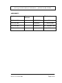
AMENDMENTS
Version
Amendment
Effective date
IRS: S: 99/ 2001
FIRST ISSUE
August 2001
IRS: S: 99/ 2001
Amendment 1
12th February 2002
IRS: S: 99/ 2001
Amendment 2
30th September 2004
IRS: S: 99/ 2006
Amendment 3
5th April 2006
Effective from 05.04.2006
Chapter/
Annexure
Page 4 of 63
Data Logger System For Railway S & T Installations
Specification no.IRS S 99/2006
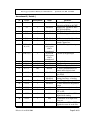
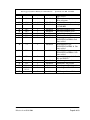
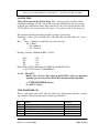
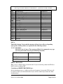
Amendment 3 ( Details )
Sl.
Clause
Amendment
status
1.
1.2
2
Add
2.
3.3
3
Modified
3.
4.
3.4
3.7
3
3
Modified
Modified
5.
6.
3.8
3.9
3
3
Modified
Modified
7.
3.10.1 (vii)
& (xvii)
3
8.
3.10.2 (iv)
3
9.
10.
11.
12.
3.13
4.1(vi)
4.2.2
4.2.7.1
3
2&3
3
1&3
Deleted &
subsequent
clause
renumbered
Deleted &
subsequent
clause
renumbered
Add
Add
Modified
Deleted
13.
4.2.10
3
Modified
14.
4.2.12
1&3
15.
16.
4.2.17
4.2.18
3
3
Add &
Modified
Modified
Modified
17.
18.
4.2.19
4.2.20
2&3
2
Add
Add
19.
4.2.21
3
Add
20.
4.2.22
3
Add
21.
4.3.1
2&3
Modified
Effective from 05.04.2006
Remarks
To clarify The scope of
inspection of Modem & CMU
Output relay capable to drive
24V Q-Series Relay
Field gear shall not load >1%
Forced Cooling to be deleted
To Print in user friendly mode
Format to include location
name& Channel no.
To delete Three position inputs
Covered by Digital Input
To include Version control
To add modem
RTU Event Capacity Defined
To delete synchronization of
control office digital clock
Storing capacity to increase
upto 10 lac
To clarify input variation
storing percentage of analog
Power Supply as per spn 144
To make modular & Ergonomic
design
To include transmission media
Common protocol between
RTU & DL
Capacity of one cabinet 1024
Digital & 64 Analog
Termination of All input Like
Wago etc
Specification of PC for CMU
upgraded to state of art & Sub
Page 5 of 63
Data Logger System For Railway S & T Installations
22.
4.3.8
3
Modified
23.
24.
4.3.9
5.5
1&3
3
Modified
Modified
25.
26.
27.
28.
29.
5.6.1
5.6.2
6.3.1
7.1
7.2
3
3
3
3
3
Modified
Modified
Add
Add
Modified
30.
7.3
3
Modified
31.
7.4
3
Add
32.
10.4
3
Add
33.
34.
35.
36.
11.1.1
11.2
11.4 (c)
11.5 &
11.5.1
Annexure
3
3
2
3
Modified
Modified
Delete
Delete
3
Add
37.
Effective from 05.04.2006
Specification no.IRS S 99/2006
clause added
FEP must have capacity to store
10 lac telegrams
Details of common protocol
Transmission rate to increase up
to 57600 BPS
Sub clause Number given
Sub clause Number given
Applied high voltage test added
Sub clause number given
IR test as per
RDSO/SPN/144/2006 & Sub
clause added
Environmental as per
RDSO/SPN/144/2006 & Sub
clause added
Applied high voltage test as per
RDSO/SPN/144/2006 & Sub
clause added
Pre-commissioning check list &
DOs and DON’Ts
Sub clause given number
“Additional” ward added
Deleted against Cl:4.1.(a) (vi)
Deleted against Cl:4.2.17
Added as per clause 4.3.9
Page 6 of 63
Data Logger System For Railway S & T Installations
Specification no.IRS S 99/2006
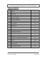
TABLE OF CONTENTS
S. No.
1
2
3
4
5
6
7
8
9
10
11
12
13
14
15
16
17
18
19
20
21
22
23
24
25
A.1
A.2
A.3
A.4
A.5
A.6
Item
Foreword
Scope
Terminology
General requirements
Technical requirements
Data logger equipment
Central monitoring unit
Functional requirements
Exception report
Test and requirements
Test equipment
Type tests
Acceptance test
Routine test
Test procedure
Visual inspection
Insulation resistance test
Environmental/climatic tests
Applied high voltage test
Quality assurance
Plant & machinery
Packing
Information to be supplied by the manufacturer
Information to be supplied by the purchaser
Annexure
Scope
Network
Message formats
Event packet
Acknowledgement Packet
Command Format
Effective from 05.04.2006
Page No.
8
8
9
9
11
12
15
16
16
18
18
18
19
19
19
20
20
20
20
20
21
21
21
22
24-63
24
24
25
34
49
50
Page 7 of 63
Data Logger System For Railway S & T Installations
Specification no.IRS S 99/2006
GOVERNMENT OF INDIA
MINISTRY OF RAILWAYS
(RAILWAY BOARD)
INDIAN RAILWAYS
STANDARD SPECIFICATIONS
FOR
DATA LOGGER SYSTEM
(TENTATIVE)
Serial No. S 99/ 2006
0
FOREWORD
0.1
This specification is issued under the fixed serial number followed by the year of
adoption as standard or in case of revision, year of latest revision.
0.2
This specification requires reference to the following specifications: IRS: S23
Electrical signalling and interlocking equipment
RDSO/SPN/144
Safety and reliability requirement of electronic signalling
equipment
IS: 9000
Basic environmental testing procedures for electronic and
electrical items
Wherever, reference to any specification appears in this document, it shall be
taken as a reference to the latest version of that specification unless the year of
issue of the specification is specifically stated.
1
SCOPE
1.1
This specification covers the technical and operational requirements of data
logger equipment, which is installed to monitor the status of the signalling gears
Effective from 05.04.2006
Page 8 of 63
Data Logger System For Railway S & T Installations
Specification no.IRS S 99/2006
at stations. It also covers minimum configuration of central monitoring unit
(CMU).
1.2
Inspection shall be carried out for data logger equipment consisting of RTU, FEP
and CMU software. Standard accessories used external to the data logger like PC
for CMU, UPS for CMU and modem etc. shall be checked during inspection for
their functional performance only required for data logger system as per
specification.
2
TERMINOLOGY
2.1
For the purpose of this specification, the terminology given in IRS: S23 and
RDSO/ SPN/144 shall apply.
2.2
Input module means an electronic module/ card used to read status of relays
(digital input) and/or level of analog signals.
2.3
Signal Conditioner means an electronic module or card used to convert analog
signals to a suitable level for recording.
2.4
SSI/ Electronic interlocking is a processor based electronic system to control
signalling equipments/ functions at any interlocked station.
2.5
Integrated power supply (IPS) is a composite module delivering various AC and
DC voltage for signalling equipment.
3
GENERAL REQUIREMENTS
3.1
The system shall chronologically monitor and record the status of various field
functions like track circuits, points, signals, operator’s push buttons/switches
(digital Inputs) and level of various analog signals like DC and AC supply
voltages, Axle counter signals etc.
3.2
The equipment shall also have the capability of statistical analysis, predict the
faults and generate failure reports. It shall be possible for the user to define fault
logics taking digital/analog inputs into consideration and generate reports for such
faults.
3.3
The equipment shall be capable of generating audio-visual alarm under defined
conditions. In addition, it shall be able to deliver non-vital relay outputs on receipt
of command from CMU. At least 8 non-vital relay outputs shall be provided. The
non vital relay output shall be in the form of potential free contacts capable of
Effective from 05.04.2006
Page 9 of 63
Data Logger System For Railway S & T Installations
Specification no.IRS S 99/2006
driving 24V 'Q' series relays These outputs may be used for non-vital functions
like radio patching of control circuits etc.
3.4
For digital inputs, potential free contacts shall be used. Analog signals shall be
scaled to a suitable limit using signal conditioner before converting to digital
signal. While tapping analog input, it shall not load the analog channel/ field gear
by more than 1% of rated load.
3.5
The system shall be suitable for working on non electrified, AC electrified and
DC electrified areas and where passenger/freight trains hauled by single phase
thyristor controlled or three phase induction motor controlled AC locomotives or
chopper controlled EMU stock are operated.
3.6
The system shall be capable of working in conjunction with conventional relay
interlocking, multi-aspect colour light signalling installations operated by lever
frames/ slides & Electronic Interlocking systems. It shall have facility to log data
received from Electronic Interlocking through a serial port.
3.7
The system (except commercial PC used for CMU) shall be capable of working in
an ambient temperature range of -100 C to +700 C and relative humidity up to
95% at ambient temperature of 400 C.Special protection against ingress of dust,
moisture etc. shall be provided.
3.8
The data logger shall be capable of being connected to a printer for obtaining a
hard copy of the function recorded. It shall be possible to print the following on
the connected printer by selecting from user friendly menu
(i) on line events as they are generated.
(ii) to print the exception report
(iii)to print the status of user specified inputs for user definable time period
3.9
The data logger shall record various field functions as indicated in para 3.10
below chronologically in the following format with name of the location at top of
every page:
Date,
3.10
time,
channel no.,
field function,
status / value
The status of various functions shall be recorded in the following way: -
3.10.1 Digital Input:
i)
Functions
Points
Effective from 05.04.2006
Status configuration
Normal or reverse (N or R), locked or
Page 10 of 63
Data Logger System For Railway S & T Installations
ii)
iii)
iv)
v)
vi)
vii)
viii)
ix)
x)
xi)
Signal
Track
Level crossing
Crank handle
Axle counter
Route
Route sections
Push buttons
SM’s key
Slots
xii)
xiii)
xiv)
xv)
xvi)
Insulation of Sig. Cable
Slots (Outgoing)
Slots (Incoming)
Switch (2 position)
General Relay
Specification no.IRS S 99/2006
unlocked
ON or OFF (Y, YY, R, G, RI, A marker)
Occupied/Free
Locked/Free
Locked/Free
Occupied /free
Locked /free
Locked / free
Pressed/released
In/Out
Given/ not given; Received / not
received
Good /bad (through ELDs)
Locked/ released
Received /Absent
Normal/ Reverse
Pickup / drop
3.10.2 Analog inputs
i)
ii)
iii)
iv)
Functions
Status configuration
Axle counter Rx signal at the tag
block
AC power supply (230/ 110V)
DC supply (12/24/48/60/110 etc.)
Temperature
Value
Value
Value
Value
The purchaser shall indicate any additional field information required to be
recorded.
3.11
The system shall be easily re-configurable to any changes required by user,
whenever modifications are carried out in the yard.
3.12
Provision for networking and remote monitoring of several data loggers from the
central place shall be provided.
3.13
Implementation of version control and change of software shall be as per
RDSO/SPN/144
4
TECHNICAL REQUIREMENTS
Effective from 05.04.2006
Page 11 of 63
Data Logger System For Railway S & T Installations
4.1
Specification no.IRS S 99/2006
Data logger system consists of:
(a) Data logger equipment which is provided near the signalling gears to be
monitored has following modules:
(i) Processor module.
(ii) Input module (digital/ analog)
(iii) Signal conditioning module
(iv) Communication module
(v) Printer 80 Col. Dot matrix (Optional)
(vi) Modem(s)
(b) Central monitoring unit (if provided) with communication facility to retrieve
data from data logger(s) provided at station(s). The central monitoring unit
shall run the diagnostic software to generate alarm and exception reports.
4.2
Data Logger Equipment:
4.2.1
The equipment shall cater for minimum 512 digital inputs (in the form of
potential free contacts) and 32 analog inputs. The system shall be expandable up
to 4096 digital & 96 analog inputs by expansion/cascading the similar equipment.
4.2.2
The equipment shall have facility to interface with Remote Terminal Unit (RTU).
The RTU shall have modules normally identical to that used in Data logger. A
RTU shall cater for minimum 32 digital and 8 analog inputs. The RTU shall have
its own processor & communication modules. RTU shall have facility to store at
least 1 Lac events. RTU should be expandable up to 64 digital inputs and 16
analog inputs. The inputs of RTU can be taken as part of data logger system and
the inputs of RTU shall be a part of the total capacity 4096 digital input and
analog input capacity of 96. The programming of the individual digital & analog
channels shall be controlled by the data loggers. It shall be possible to connect
maximum of 4 RTUs. Alternatively, the RTU can exist with separate ID. There
shall be no loss of data due to power failure.
4.2.3
RTU shall use standard current loop serial interface for data transmission. It shall
be possible to connect RTU up to 3 Km. from main Data logger equipment.
4.2.4
Signal conditioning module shall convert analog signals like 230 VAC, 110 VAC,
110 VDC, 60 VDC, 24 VDC, 12VDC and axle counter RX voltages etc. to
suitable level for recording. Normally all AC voltages shall be at commercial
frequency of 50 HZ except for Axle counter which is at 5KHZ. When an analog
channel is not connected, it shall not pick up any noise.
Effective from 05.04.2006
Page 12 of 63
Data Logger System For Railway S & T Installations
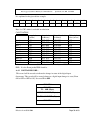
4.2.5
Specification no.IRS S 99/2006
Configuration of analog channels may be as under;
Channel
1
2
3
4
5
6
7
8
9-16
Nominal Voltage DC or Voltage Range for no
AC (RMS)
alarm (adjustable)
230 AC
207- 253
110 AC
99- 121
110 AC
99- 121
110 DC
99- 121
60 DC
55- 69
60 DC
55- 69
24 DC
22.5-28
24 DC
22.5-28
1.0 AC,5KHz
-
Or as specified by purchaser.
4.2.6
Display shall be provided on the front panel of the data logger to display current
status / faults/ alarms along with time stamp. It shall be possible to display
faults/ alarms generated up to one week earlier on the panel. At least two row
display shall be used with at least 16 characters in each row.
4.2.7
The equipment shall have real time clock for recording time at which the status
of the particular information has changed. The real time clock on data logger
should get synchronized with the central monitoring unit. The cascaded Data
logger(s) shall also synchronize their clocks with the real time clock of master
Data logger.
4.2.8
Opto-couplers may be provided to electrically isolate external digital inputs
(relay contacts) from the equipment. Self-diagnostics shall be provided in the
system. Any fault in the system shall generate error message in the system panel
and generate alarm in the CMU.
4.2.9
The hardware structure of the system shall be modular.
4.2.10
Event logging facility for minimum 10 Lac events shall be provided in a Data
logger. Data shall be recorded on first in – first out basis so that latest data is
available in the system. There should be no loss of data from the data logger
memory in case of power supply failure of data logger.
4.2.11
Scanning interval for digital inputs shall be less than 20 milliseconds. Change in
status of digital signal shall only be recorded.
Effective from 05.04.2006
Page 13 of 63
Data Logger System For Railway S & T Installations
Specification no.IRS S 99/2006
4.2.12
Scanning interval for analog signals like DC or AC supply voltage, temperature,
axle counter RX voltage etc. shall be less than 1 second. Variation of more than
5% of the nominal value from the last recorded value, provided it has gone 5%
beyond the nominal value, shall be recorded.
4.2.13
Accuracy of measurement of analog signals shall be better than 1% within
±40% of nominal value.
4.2.14
The equipment shall have facility to receive serial data from external equipment
like Electronic Interlocking, Integrated Power Supply etc. and record it with
time stamp.
4.2.15
The software of the system shall be of approved type and written in a structured
format so that the purchaser can reconfigure it, if required. The software shall
have clear bifurcation between generic software and application software.
4.2.16
At least 6 serial ports shall be provided for communication with other data
loggers, CMU, RTU, EI, IPS etc.
4.2.17
Power Supply: The system shall work on 24V DC (+20%, -30%). Railways will
provide 24VDC input supply.
4.2.18
19” rack mountable and 3/4/6 U high cabinets made of aluminum of minimum
thickness 2mm should be used for housing the PCB cards to achieve modular
and ergonomic design for good maintainability. The cabinet should be powder
coated. The front and backsides of the cabinets shall have the facility for
locking the equipment.
4.2.19
Data Logger shall be capable of working with different transmission media like
under ground telecom cable, microwave (Digital or Analog) & OFC. The
provision of either in-built modem or external modem is acceptable. The data
logger equipment will continuously check the modem status and give the
necessary reset as required to eliminate modem hanging condition. The modem
will be housed within the data logger cabinet. The data logger shall be
compatible to the following media:
(i) Main telecom cable.
(ii) Quad cable.
(iii) Analog channel of OFC, digital microwave or analog microwave.
(iv) 64 KBPS data channel on OFC or digital microwave.
Effective from 05.04.2006
Page 14 of 63
Data Logger System For Railway S & T Installations
Specification no.IRS S 99/2006
4.2.20
Communication between data logger & RTU shall also be as per
communication protocol mentioned in clause 4.3.9.
4.2.21
Cards and terminals required for up to minimum 1024 digital inputs 32 analog
inputs, signal conditioning modules etc. shall be accommodated in one rack of
19" width.
4.2.22
For termination of external digital and analog inputs, international quality
terminals of WAGO/ Phoenix etc. makes shall be used as per RDSO SPN/144.
All wires should be neatly bunched in horizontal and vertical channels.
4.3
CENTRAL MONITORING UNIT (CMU):
4.3.1
SOFTWARE CONFIGURATION
4.3.1.1
The database management system i.e. MS SQL server or Interbase shall be
used to cater for basic function of Data loggers at CMU level. Only licensed
software shall be used.
4.3.2
HARDWARE CONFIGURATION
4.3.2.1
Central monitoring unit shall be state of art PC ( of reputed brand ) based
system working on commercial supply of 230VAC, 50Hz. The minimum
configuration shall be as specified by RDSO from time to time. Presently
minimum configuration must be as under:
(i)
Pentium 4 or equivalent processor 3 GHz, 256MB RAM, 2 × 20 GB
HDD with disk mirroring, 1.44” FDD, SVGA colour monitor (17”)
sound card with speaker, 56 KBPS modem, key board, optical mouse, 10
/ 100T LAN card, CD writer and inkjet printer .
(ii)
UPS with minimum 6 hours battery backup for central monitoring unit.
(iii)Software tools.
4.3.2
Central monitoring unit shall have Graphical User Interface (GUI) based
software and retrieve data from all Networked data loggers (up to 32) at various
stations. It shall store data in standard data base files. The CMU shall also be
capable of analyzing the data & generate reports & audio visual alarms on
defined conditions. It shall be possible to compress the data and take backup on
floppy.
Effective from 05.04.2006
Page 15 of 63
Data Logger System For Railway S & T Installations
Specification no.IRS S 99/2006
4.3.3
Software used for analysis of data, prediction of faults etc. in central monitoring
unit shall be of approved type and written in a structured format so that
purchaser can reconfigure it, if required. A copy of software shall be supplied in
CD.
4.3.4
It shall be possible to display the status of signalling gears at any selected time
in graphic form for any selected station yard on the central monitoring unit.
4.3.5
It shall be possible to retrieve the stored data & simulate train movement on the
central monitoring equipment.
4.3.6
It shall be possible to send commands to various Data loggers to activate audio,
visual alarm or operate an electromagnetic relay.
4.3.7
It shall be possible to share data available in CMU by other PCs through available
local area network where this data can be used for train charting / passenger
information purpose.
4.3.8
Front End Processor (FEP) shall be provided to continuously retrieve data from
station data loggers. FEP must have capacity to store 10 lac telegrams. It should
have 6 ports.
4.3.9
The communication protocol for transmitting data and command between data
logger and CMU is given in Annexure.
5
FUNCTIONAL REQUIREMENTS:
5.1
The system shall generate audiovisual alarm in ASM’s/ Signal Maintainer’s room
in the case of power supply failure (battery voltage low) or battery charger
defective with acknowledgement facility.
5.2
Each data logger shall have it’s own identity code which shall be transmitted
along with data packet to central monitoring unit.
5.3
Events recorded at each station shall be continuously transmitted to central
monitoring unit. Response time of data transfer shall not exceed 10 sec.
5.4
In case of loss of data, retransmission of data shall take place.
5.5
Data transfer rate shall be 57600 BPS with fallback facility to lower rates.
5.6
EXCEPTION REPORT:
Effective from 05.04.2006
Page 16 of 63
Data Logger System For Railway S & T Installations
5.6.1
Specification no.IRS S 99/2006
The Data logger equipment shall be capable of generating following exception
reports;
i)
ii)
iii)
iv)
v)
vi)
Battery Low voltage
Battery charger defective
Under wheel flashing of points
Signal lamp failure
Blanking of Signals
Route section not released after passage of train due to track circuit
failure.
vii)
Point Failure – point detection not available after set time period.
viii) Track circuit failure
ix)
Fuse Blown OFF
x)
Timer not properly set for 120 Sec.
xi)
Sluggish relay operation
xii)
Signal cable low insulation
xiii) Route not set when operation is valid.
xiv) Push button stuck.
xv)
Signal over shoot.
xvi) Wrong operation
xvii) Axle Counter RX low level
xviii) Bobbing of track, point, signal, crank handle, Level X-ing or Ground
frame repeater relay
xix) Point repeated operation
xx)
Non sequential shunting of tracks
5.6.2
The CMU shall be capable of generating following additional exception reports.
i)
ii)
iii)
iv)
v)
Emergency cancellation of route
Panel failure due to power failure
Late start of a train (train operation)
Late operation of signals with respect to local trains (train operation)
Route failure online indication with analysis of the stage at which it had
failed.
vi)
Non-signal movement (train operation)
vii) Total on time of lamp (to assess working life of signal lamp)
viii) Total number of operations of the relay (to assess life of relay)
ix)
Emergency Point operation
x)
Emergency Route Release
xi)
Emergency Sub Route Release
xii) Overlap release
xiii) Emergency Crank Handle release
Effective from 05.04.2006
Page 17 of 63
Data Logger System For Railway S & T Installations
xiv)
xv)
xvi)
xvii)
xviii)
Specification no.IRS S 99/2006
Calling on operations
Slot operations
Historical replay of events in a yard in graphical manner.
Circuit progression. Railway shall provide logic for the same.
Any other exception report.
5.7
Exception condition shall be stored in the data logger chronologically and displayed
one by one on the front panel through a toggle switch.
5.8
Data loggers of all stations shall send status report to the Central monitoring unit
continuously. Status information shall be processed at the central monitoring unit
and audio visual alarm generated for the fault / alarm condition
6
TESTS AND REQUIREMENTS
6.1
Conditions of Tests
Unless otherwise specified all tests shall be carried out at ambient atmospheric
conditions.
6.2
For inspection of material, relevant clauses of IRS: S 23 and RDSO/SPN/144
shall apply.
6.2.1
Test Equipment
i)
ii)
iii)
iv)
v)
vi)
vii)
Dual beam oscilloscope of 20 MHz bandwidth
Digital multimeters - 3.1/2 digit display with facility of diode & transistor
testing with 1% accuracy
EPROM Programmer and UV eraser
Megger (500V)
PC
Test jig
Any other test equipment considered necessary.
6.3
Type Tests
6.3.1
The following tests shall constitute type tests:
a)
b)
c)
d)
Visual inspection as per Clause 7.1
Insulation Resistance tests as per Clause 7.2
Card-level functional tests on all the cards.
System level functional tests.
Effective from 05.04.2006
Page 18 of 63
Data Logger System For Railway S & T Installations
e)
f)
Specification no.IRS S 99/2006
Environmental/climatic tests as per Clause 7.3
Applied High Voltage Test as per Clause 7.4
6.3.2
Any other tests shall be carried out as considered necessary by the purchaser.
6.3.3
Only one equipment shall be tested for this purpose. The equipment shall
successfully pass all the type tests for proving conformity with this specification.
If the equipment fails in any of the type tests, the purchaser or his nominee at his
discretion, may call for another equipment/card(s) of the same type and subject it
to all tests or to the test(s) in which failure occurred. No failure shall be
permitted in the repeat test(s).
6.4
Acceptance Tests
6.4.1
The following shall comprise acceptance tests:
a)
b)
c)
Visual inspection (Clause 7.1).
Insulation Resistance tests (Clause 7.2).
System level functional tests.
6.4.2
Any other tests shall be carried out as considered necessary by the purchaser.
6.5
Routine tests
6.5.1
The following shall comprise the routine tests and shall be conducted by
manufacturer on every equipment and the test results will be submitted to the
inspection authority before inspection. The application software in proper format
shall also be submitted to the inspection authority in advance.
a)
b)
c)
d)
Visual inspection (Clause 7.1)
Insulation Resistance tests (Clause 7.2)
Card level functional test on all the cards.
System level functional test.
6.5.2
Any other tests shall be carried out as considered necessary by the purchaser.
7
TEST PROCEDURE
The test procedure shall be based on the system design. The methodologies to be
adopted for various tests shall be decided taking into account the system
design/configuration.
Effective from 05.04.2006
Page 19 of 63
Data Logger System For Railway S & T Installations
7.1
Specification no.IRS S 99/2006
Visual Inspection
The equipment shall be visually inspected to ensure compliance with the
requirement of Clauses 3 to 5 of this specification. The visual inspection will
broadly include –
7.1.1
System level checking:
7.1.2
Card level checking:
7.1.3
Constructional details.
Dimensional check .
General workmanship.
Configuration.
Mechanical polarisation on cards .
General track layout .
Quality of soldering and component mounting.
Conformal coating.
Legend printing.
Green masking.
Module level checking:
General shielding arrangement of individual cards.
Indications and displays.
Mounting and clamping of connectors.
Proper housing of cards.
7.2
Insulation Resistance Test
7.2.1
Insulation Resistance Test shall be conducted as per RDSO/SPN/144
7.3
Environmental / climatic tests
7.3.1
Environmental / climatic tests shall be conducted as per RDSO/SPN/144
7.4
Applied High Voltage Test
7.4.1 Applied High Voltage Test shall be conducted as per RDSO/SPN/144
8
QUALITY ASSURANCE
Effective from 05.04.2006
Page 20 of 63
Data Logger System For Railway S & T Installations
Specification no.IRS S 99/2006
8.1
All materials & workmanship shall be of good quality.
8.2
Since the quality of the equipment bears a direct relationship to the manufacturing
process and the environment under which it is manufactured, the manufacturer
shall ensure Quality Assurance Program of adequate standard.
8.3
Validation and system of monitoring of QA procedure shall form a part of type
approval. The necessary Plant, Machinery and Test instruments as given below
shall be available with the manufacturer.
8.3.1
Plant & Machinery:
i) Ultrasonic cleaner/Aqueous cleaner for automatic cleaning
ii) Burn in chamber
iii) Anti-static assembly
iv) EPROM Programmer and UV Eraser
v) Microprocessor development system
vi) Computer aided design system
8.3.2
All test instruments as given in Cl. 6.2.1 shall be available with the
manufacturer.
8.4
Along with the prototype sample for type test, the manufacturer shall submit the
Quality Assurance Manual.
9
PACKING
The equipment and its sub assemblies shall be packed in thermocole boxes
and the empty spaces shall be filled with suitable filling material. Before
keeping in the thermocole box, the equipment shall be wrapped with bubble
sheet. The equipment shall be finally packed in a wooden case of sufficient
strength so that it can withstand bumps and jerks encountered in a road/ rail
journey.
10
INFORMATION TO BE SUPPLIED BY THE MANUFACTURER
Following documents should be supplied along with the system:
10.1
Mechanical drawings of each sub-system/ rack.
10.2
Trouble shooting chart.
10.3
Installation and Maintenance Manual.
Effective from 05.04.2006
Page 21 of 63
Data Logger System For Railway S & T Installations
Specification no.IRS S 99/2006
10.4
Pre-commissioning check list, DOs and DON'Ts of data logger system
including RTU, CMU & FEP in the User’s manual.
11
INFORMATION TO BE SUPPLIED BY THE PURCHASER
11.1
Total number of digital and analog inputs to be monitored calculated as under.
11.1.1
The tenderer should give number of digital inputs required by calculating the
inputs from the list given below:
a)
b)
c)
d)
e)
f)
g)
h)
i)
j)
k)
l)
All ECRs,
All HRs, HHRs, DRs or equivalent
All point operating relays NWRs, RWRs or equivalent
All point indicating NWKRs, RWKRs or equivalent
All buttons and knob relays
All track and axle counter relays
All timer repeater relays
Intermediate interlocking relays which tenderer need to monitor through
data-logger e.g. UCR, ASR, JSLR etc. or equivalent
All relays related with emergency operations e.g. route cancellation,
overlap cancellation, point operation under emergency, crank handle
release, gate release etc.
CH, GF, LX release and indication relays.
All relays related with block instruments with or without axle counters and
SM key.
Any other relay required to be monitored.
11.1.2 Details of Analog inputs to be monitored in local area.
Type of input
No. of channels required
230 V AC
110 V AC
12 V AC
110 V DC
60 V DC
24 V DC
18 V DC
12 V DC
Axle counter evaluator input
voltages (RX) (unit-wise)
Effective from 05.04.2006
Page 22 of 63
Data Logger System For Railway S & T Installations
Specification no.IRS S 99/2006
Any other voltage
11.1.3
Whether RTU is required for monitoring of the equipments at distant place, no.
of digital and analog inputs required in RTU.
Details of analog inputs to be monitored from RTU should be given in the
format as given below:
Type of input
(Digital/Analog)
No. of
channels
Approximate distance from
data-logger
11.2
Additional exception reports (other than those mentioned in para 5.6) to be
generated.
11.3
List of functions (in addition those mentioned in para 3.10) to be monitored.
11.4
(a)
Central monitoring equipment (CMU) required – Yes/ No.
(b)
FEP required – Yes/NO
If YES, indicate whether it is to be provided at the same station or at a
remote place like control office etc.
11.5
Whether printer is required with data logger (at the station) : Yes/ No
Effective from 05.04.2006
Page 23 of 63
Data Logger System For Railway S & T Installations
Specification no.IRS S 99/2006
Annexure
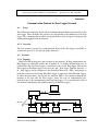
Communication Protocol for Data Logger Network
A.1
Scope
This Document completely details out the communication methods and protocols for the
data logger. These methods and protocols are independent of the hardware of the data
logger. The communication methods and protocols have been designed to bring out the
maximum throughput from the network.
A.1.1 Overview
The data structure protocol for communication between the data loggers and CMU is
explained in paras A.4, A.5 and A.6 of this Annexure.
A.2
Network
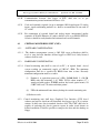
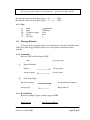
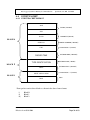
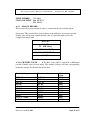
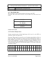
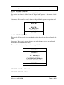
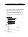
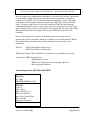
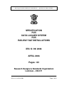
A.2.1 Topology
Ring Network topology has been adopted in this network. In Ring configuration the
Data loggers are connected serially one to another. If ‘n’ number of Data loggers are in
network then the first Data logger is connected to the second Data logger and second
Data logger to third Data logger so on up to the ‘nth’ Data logger. Then the first and ‘n
th ‘ Data loggers will be connected to the Front End Processor ( FEP ) individually to
make the network as closed ring. Each Data logger is connected with other Data loggers
in either direction with 4 wire leased line modems. FEP is also connected through the
modems to the first and last Data loggers. Since this type of configuration gives
individual one to one communication between Data loggers, so event data can be placed
into network immediately and simultaneously by all the Data loggers.
FEP
CMU
Modem
DL 1
DL 2
DL 3
DL n
Data Logger System Network
Effective from 05.04.2006
Page 24 of 63
Data Logger System For Railway S & T Installations
Specification no.IRS S 99/2006
Direction A is data flow from Data logger n , n-1,…..1 - FEP.
Direction B is data flow from Data logger 1 , 2 ,……n - FEP.
A.2.2 Port
(i)
(ii)
(iii)
(iv)
(v)
Mode:
Baud:
Character Length:
Parity:
Stop bits:
Asynchronous
57600 bps
8 bits
none
1
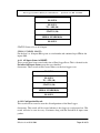
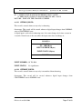
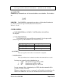
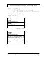
A.3 Message Formats
Two types of message formats have been implemented. One for Commands from
CMU to any Data Logger / FEP and other is for event packets transmission in the
network.
A.3.1 Commands.
Between CMU and Data Logger / FEP
CMU
(a)
(b)
Data Logger /FEP
Request Respond
Request
Accept request
Accept response
Send response
Send all get Reply
Broad cast request
Accept Broadcast request
Accept reply
Reply from all
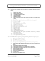
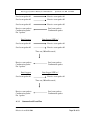
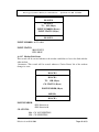
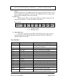
A.3.2 Event Packets.
Between two Data Loggers or Data Logger and FEP.
Data Logger n
Effective from 05.04.2006
Data Logger / FEP n-1
Page 25 of 63
Data Logger System For Railway S & T Installations
Specification no.IRS S 99/2006
Send event packet #1
Receive event packet #1
Send event packet #2
Receive event packet #2
Send event packet #3
Receive event packet #3
Receive event packets
Confirmation packet
For 3 packets
Send event packets
Confirmation packet
Data Logger n
Data Logger / FEP n-1
Send event packet #1
Receive event packet #1
Send event packet #2
Receive event packet #2
Time out (300 milliseconds)
Receive event packets
Confirmation packet
For 2 packets
Send event packets
Confirmation packet
Data Logger / FEP n-1
Data Logger n
Send event packet #1
Receive event packet #1
Time out (300 milliseconds)
Receive event packets
Confirmation packet
For 1 packet
A.3.3
Send event packets
Confirmation packet
Command and Event Flow
Effective from 05.04.2006
Page 26 of 63
Data Logger System For Railway S & T Installations
Specification no.IRS S 99/2006
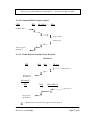
A.3.3.1 Command flow for request-respond
CMU
FEP
DL 1 DL 2 ….. DL n
Request to DL 2
Accept request
Send response
Accept response
From DL 2
A.3.3.2 Packet flow for event data in two directions
Direction I
FEP
DL 1
DL 2 ….
DL n-2
Send event ‘x’
Accept event
From DL n-2
Direction II
FEP
DL n
DL n-1 DL n-2
Send event ‘x’
Accept event
From DL n-2
= Retransmission to the next Data Logger in the other direction.
Effective from 05.04.2006
Page 27 of 63
Data Logger System For Railway S & T Installations
A.3.3.3
Specification no.IRS S 99/2006
Event Packets Communication:
The event packets created in the DL will be sent immediately in both the directions. The
event packets received from one direction is retransmitted to the other direction. The
event packet is maintained in the buffer till it is acknowledged.
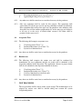
On failure of acknowledgement the event packets are tried again for transmission
after the time out of 3 Seconds.
This is repeated and tried for three times with the same time-out of 3 Seconds. If
acknowledgment is not received even after three trials, then time-out will be changed to
120 Seconds, thereafter it will be tried every 120 Seconds till it is acknowledged.
The acknowledgement for the event packets are sent for every three event packets
received or if the time between received packet exceeds 300 milliseconds.
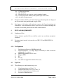
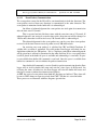
On receiving any event packet it is validated for CRC and Shift Checksum. If
validity fails, no action is performed. For valid packets Data Logger will check for any
duplication within the last 100 packets. If it is a duplicate packet then acknowledgement
will be given but it will not be transmitted in the other direction. If it is a new packet then
it will be placed in the buffer if space is available and acknowledge is sent back. If space
is not available then buffer full command is sent back. Once the space is available then
buffer free command is sent to reinitiate the packets transmission.
Once buffer-full command is received back for packet transmission then the Data
logger will set itself to buffer full status and wait for a time lapse of 60 Seconds. On
receiving the status of buffer free, the Data Logger will clear the buffer-full status and
time lapses counts to initiate the transmission of packets.
At FEP, the received event packets from both the directions are buffered. These data will
be sent to CMU whenever request received from CMU. Till then it is stored in buffer.
These processes are illustrated with flow diagrams given below.
Effective from 05.04.2006
Page 28 of 63
Data Logger System For Railway S & T Installations
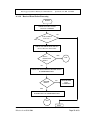
A.3.3.4
Specification no.IRS S 99/2006
Received Event Packet Processing
ENTER
CHECK FOR CRC and Shift
Checksum VALIDITY
NO
YES
IS IT VALID in
both cases ?
CHECK FOR THE DUPLICATION in
the last 100 events in the buffer
IS IT A
DUPLICATE
PCKT=?
YES
ACK
NO
CHECK FOR TRANSMITTING BUFFER SPACE
IN OTHER DIRECTION
NO
BUFFER
FREE=?
SEND BUFFER
FULL
COMMAND
NO
YES
STORE THE RECVD. PCKT IN TRANSMITTING
BUFFER SPACE IN OTHER DIRECTION
ACK
EXIT
Effective from 05.04.2006
Page 29 of 63
Data Logger System For Railway S & T Installations
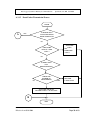
A.3.3.5
Specification no.IRS S 99/2006
Event Packet Transmission Process
ENTER
A
IS BUFFER FULL
STATUS RECEIVED
FROM OTHER DATA
YES
NO
TRANSMIT
PCKT,
SET
TIMELAPSE
=3SECS
CHECK THE
PCKT IS A NEW
PCKT ?
NO
IS TIME LAPSE
FOR
RETRANSMISSION
NO
CHECK THE
NUMBER OF
TRANSMITTED
EXIT
TRANSMIT PCKT
SET TIME
LAPSE=3SECS
TRANSMIT THE PCKT
SET TIME LAPSE = 120 SECONDS
B
EXIT
Effective from 05.04.2006
Page 30 of 63
Data Logger System For Railway S & T Installations
Specification no.IRS S 99/2006
A
YES
IS BUFFER CLEAR
STATUS RECEIVED
FROM OTHER DATA
LOGGER ?
CHECK THE 60
SECONDS TIME
LAPSE OVER ?
NO
YES
CLEAR THE BUFFER FULL
STATUS
CLEAR THE TIME LAPSES
OF ALL PCKTS.
B
Effective from 05.04.2006
Page 31 of 63
Data Logger System For Railway S & T Installations
Specification no.IRS S 99/2006
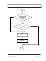
A.3.3.6 Acknowledgement Process for Event Packet
ACK
CHECK THE RECEIVED PCKTS
COUNT=3 OR NOT
YES
IS IT
=3?
YES
NO
CHECK THE TIME LAPSE OF 300ms.
NO
IS TIME
LAPSE IS
OVER=?
YES
SEND ACK.
EXIT
Effective from 05.04.2006
Page 32 of 63
Data Logger System For Railway S & T Installations
A.3.3.7
Specification no.IRS S 99/2006
Commands Communication:
Commands always originated from the CMU to facilitate control actions on any one or all
the Data Logger/s in the network. Buffer full and Buffer free commands are the only
commands originated by Data Loggers for control of event packets flow. The commands
always work in the Request and Response style.
Effective from 05.04.2006
Page 33 of 63
Data Logger System For Railway S & T Installations
A.4
EVENT PACKET
A.4.1
EVENT PACKET FORMAT
Specification no.IRS S 99/2006
AAH
START (2 BYTES)
55H
ID NO
ADDRESSS (1BYTE)
BLOCK 0
SERL NO
CRC
PACKED TIME
TYPE IDENTIFICATION
BLOCK
SERIAL NUMBER (2 BYTES)
VALIDATION-1 (1 BYTE)
PACKED TIME (4 BYTES)
PACKET TYPE (1 BYTE)
1
DATA
SHIFT CHECK SUM
PACKET DATA (3 BYTES)
VALIDATION – 2 (1 BYTE)
BLOCK 2
BBH
END
Event packet consists three blocks as shown in the above frame format.
i)
ii)
iii)
Block 0
Block 1
Block 2
Effective from 05.04.2006
Page 34 of 63
Data Logger System For Railway S & T Installations
Specification no.IRS S 99/2006
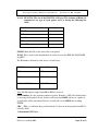
A.4.1.1 BLOCK 0: The size of the BLOCK 0 is 10 bytes. The structure of Block 0 is
common for any type of event packet and it is having the following five
fields.
Field Name
Size in bytes
START
2
ID Number
1
Serial No.
2
CRC
1
Packed Time
4
START: $AA and $55 are the start of the event packet.
ID NO: This is used for the identification of various devices like FEP, DATALOGGER
and RTU.
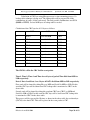
The ID numbers allotted for each device is listed below.
DEVICE
ID RANGE
FEP
00H
RTU
01H - 40H
DATALOGGERS
41H – 7FH
Note: The ID numbers range from 80H to FFH are reserved.
Serial Number: It is the sequence number of packet. With this CMU will identify that it
is receiving all the packets or not. Serial no will start from 0000H, when ever a packet is
created count will be incremented by one, and will roll over to 0000H after reaching
FFFFH.
CRC : This is a validation byte provided for the 11 bytes in the data packet from ID No
to DATA fields.
Calculation of CRC byte:
Effective from 05.04.2006
Page 35 of 63
Data Logger System For Railway S & T Installations
Specification no.IRS S 99/2006
Calculation of CRC byte using Microprocessor is time-consuming process. So
look up table technique is being used. The lookup table will be prepared for all the
combinations of words (16 bits each word). The total possible combinations are 65536
(0000H to FFFFH). So total 64K bytes of lookup-table is needed.
Calculation of the CRC byte for all 11 bytes as follows:
MSB
LSB
RESULT
1
ID No
Serial No MSB
CRC1
2
CRC1
Serial No LSB
CRC2
3
CRC2
Time-1
CRC3
4
CRC3
Time-2
CRC4
5
CRC4
Time-3
CRC5
6
CRC5
Time-4
CRC6
7
CRC6
Type identifier
CRC7
8
CRC7
Data-1
CRC8
9
CRC8
Data-2
CRC9
10
CRC9
Data-3
CRC10
The CRC10 will be the CRC field in event packet.
Time-1, Time-2, Time-3 and Time-4 are 4 bytes of packed Time filed from MSB to
LSB respectively.
Data-1, Data-2 and Data-3 are 3 bytes of DATA field from MSB to LSB respectively.
First word will be framed by taking ID no as MSB and Serial No MSB as LSB. For this
word the CRC byte will be taken from CRC lookup table is mentioned as CRC1 in the
above table.
Second word will be framed by taking this resultant CRC byte (CRC1) as MSB and
Serial No LSB as LSB. For this word the CRC byte will be read from CRC lookup table
is mentioned as CRC2 in the above table.
This process will be repeated for 10 times as shown in the above table, the resultant byte
(CRC10) is the final CRC. This will be placed in the event packet as CRC.
Effective from 05.04.2006
Page 36 of 63
Data Logger System For Railway S & T Installations
Specification no.IRS S 99/2006
PACKED TIME:
Time will be stored in the Packed Form. This is a long word size and time will be
calculated in multiples of 1/64 second. This long word will hold time for one year and
even/odd year identification. In the long word least 31 bits will represent the time. The
32nd bit will be used to represent the year status, ‘1’ for odd year and ‘0’ for even year.
The equation to build packed time from the real time is given below.
Packed time = (Days x 24 x 60 x 60 x 64) + (Hr x 60 x 60 x 64)+(Mt x 60 x 64) + (Sec x
64).
Here
Days = Number of completed days till present date
Hr = Hours
Mt = Minutes
Sec = Seconds
Example: Consider 12th March 2003, 21:16:24
Days
= 70
Hr
= 21
Mt
= 16
Sec
= 24
Packed Time=(70*24*60*60*64+21*60*60*64+16*60*64+24*64)
= 391973376 decimal / 175D0A00 hexa
A.4.1.2
BLOCK 1:
Block 1 size is 4 bytes. The values in the BLOCK 1 will vary depending
upon the type of event packet. BLOCK1 is having the following fields.
a) TYPE IDENTIFIER (1 bytes)
b) DATA (3 bytes)
TYPE IDENTIFIER (TI):
This is a byte-sized value and it indicates packet type. Each packet will have a unique
type identifier. The below table shows various type identifiers.
TI
00H
01H
02H
03H
04H
Details
Digital Record
Analog Record
Time Difference
Time Write Low
Communication Status Packets
Effective from 05.04.2006
USAGE
Compulsory
Compulsory
Compulsory
Compulsory
Optional
Page 37 of 63
Data Logger System For Railway S & T Installations
05H
06H
07H
08H
09H
0AH
0BH
0CH
0DH
0EH
0FH
10H
11H
12H
13H
14H
15H
16H
17H
Health Record
Periodical All Inputs Status
All Inputs Status at Reset
Reserved
Configuration Record
Time Write High
Reserved
Reserved
Digital Fault
Analog Fault
Reserved
Digital Chattering On
Digital Chattering Off
Modem Link Status
Reserved
Reserved
Reserved
Reserved
Reserved
Specification no.IRS S 99/2006
Compulsory
Compulsory
Compulsory
Optional
Compulsory
Optional
Optional
Compulsory
Compulsory
Compulsory
DATA:
This field is having 3 bytes and the structure of these bytes will vary depending
upon packet. All the packets are explained in the following sections.
A.4.1.3 BLOCK 2:
BLOCK 2 size is 2 bytes. The structure of Block 2 is common for any type
of event packet and it is having the following two fields.
Field Name
Size in bytes
Shift Checksum
1
End ( BBh )
1
SHIFT CHECKSUM:
This is also a validation byte provided for the 11 bytes in the data packet from ID No to
DATA fields excluding CRC.
Calculation of SHIFT CHECKSUM byte:
In the calculation process, each byte in the record structure (leaving the CRC byte) will
be rotated to left by one bit and then these bytes will be summed up to form the ‘Shift
checksum byte’.
Effective from 05.04.2006
Page 38 of 63
Data Logger System For Railway S & T Installations
Specification no.IRS S 99/2006
It is explained in the given below example.
Byte1
Byte2
Byte3
Byte4
Byte5
Byte6
Byte7
Byte8
Byte9
Byte10
Byte11
Byte12
48H
00H
31H
10H
90H
00H
C2H
13H
87H
FFH
FFH
31H
Byte 4 is CRC which is excluded in calculation.
CALCULATION
Actual value
(in Hex )
Byte 1
Byte 2
Byte 3
Byte 5
Byte 6
Byte 7
Byte 8
Byte 9
Byte 10
Byte 11
Byte 12
48H
00H
31H
90H
00H
C2H
13H
87H
FFH
FFH
31H
Actual value
(in Binary)
Rotated by 1 value
(in binary)
0100 1000
1001 0000
0000 0000
0000 0000
0011 0001
0110 0010
1001 0000
0010 0001
0000 0000
0000 0000
1100 0010
1000 0101
0001 0011
0010 0110
1000 0111
0000 1111
1111 1111
1111 1111
1111 1111
1111 1111
0011 0001
0110 0010
Shift checksum or Resultant byte = 2DH
Shifter by 1
value (in hex)
90H
00H
62H
21H
00H
85H
26H
0FH
FFH
FFH
62H
END : It is the Event packet END identifier.
A.4.2
DIGITAL RECORD :
This record will be created to indicate the change in status of the digital input.
Occurrence: This record will be created whenever a digital input changes its state (From
ON to OFF or OFF to ON). Its record ID is 00H.
BLOCK 0
BLOCK 1
TI - 00H (1Byte)
INPUT NUMBER(2Bytes)
STATUS OF INPUT (1Byte)
BLOCK 2
Effective from 05.04.2006
Page 39 of 63
Data Logger System For Railway S & T Installations
Specification no.IRS S 99/2006
INPUT NUMBER:
1 TO 4096
STATUS OF INPUT : 00h PICK UP
FFh DROP
A.4.3 ANALOG RECORD :
This record will be created whenever there is variation in the any of analog inputs.
Occurrence: This record will be created whenever the difference of previous recorded
channel value and present scanned channel value of a particular input crosses the
configured tolerance limit.
BLOCK 0
BLOCK 1
TI - 01H (1Byte)
CHANNEL VALUE(2Byte)
CHANNEL NUMBER (1Byte)
BLOCK 2
A.4.3.1 CHANNEL VALUE : 0 TO 4095 (Value 4095 is equivalent to Maximum
possible Channel value for that input). The nominal voltages and their corresponding
maximum voltages are shown in the below table.
Nominal voltage
Maximum voltage
230V AC
110V AC
110V DC
60V DC
24V AC
24V DC
18V DC
12V DC
150mv
3V or 2V, 5KHZ
6V DC
330V AC
170V AC
170V DC
90V DC
50V DC
50V DC
50V DC
25 VDC
150 mv
3000mv
10V DC
Effective from 05.04.2006
Maximum
value
4095
4095
4095
4095
4095
4095
4095
4095
4095
4095
4095
Page 40 of 63
Data Logger System For Railway S & T Installations
A.4.3.2 CHANNEL NUMBER:
Specification no.IRS S 99/2006
1 TO 96
The temperature record will also be created with the same analog record ID with channel
number as 00h. The channel value MSB made 00 and LSB gives the temperature
measured.
A.4.4 TIME DIFF ID:
To notify the difference between the packed time and with RTC chip time.
Occurrence: This record will be created whenever there is a difference in packed time and
RTC chip time. The data logger compares the chip time with the packed time periodically
and to record the difference if any
BLOCK 0
BLOCK 1
TI - 02H (1B)
STATUS BYTE (1B)
DIFFERNCE TIME
(2B)
BLOCK 2
VALUE
STATUS BYTE:
00H if RTC Time > Packed Time
FFH if RTC Time < Packed Time
DIFFERNCE TIME VALUE: RTC Time ~ Packed Time
A.4.5
TIME WRITE :
This record will be created whenever time set command was sent from CMU.
Occurrence: This record is created whenever time was set from CMU, two records were
created, one for lower 3 bytes and another for upper 3 bytes of packed time that has been
sent from the CMU. These two records differ in record Id, for the lower 3 bytes it is 03H.
For the higher three bytes it is 0AH.
Effective from 05.04.2006
Page 41 of 63
Data Logger System For Railway S & T Installations
Specification no.IRS S 99/2006
BLOCK 0
BLOCK 1
TI - 03h / 0Ah (1Byte)
Set Time (3Byte)
BLOCK 2
A.4.6
Communication Status Packets:
These records were created to log network status for later analysis. the network
communication health status.
Occurrence: These records will be created for every 68 minutes approximately.
BLOCK 0
BLOCK 1
TI - 04H (1B)
PACKETS COUNT (2B)
SERIAL NUMBER (1B)
BLOCK 2
A.4.6.1 PACKET COUNT:
Transmitted packets (or) Received packets (or) Pending packets (or) Duplication
packets (or) Fail packets for two network ports.
A.4.6.2 SERIAL NUMBER: It specifies the type of Packets count.
Serial Number
01h
02h
03h
04h
05h
06h
07h
08h
Details
Transmitted Packets Count (Direction-A)
Receive Fail Packets Count (Direction-A)
Pending Packets Count (Direction-A)
Received Packets Count (Direction-A)
Transmitted Packets Count (Direction-B)
Receive Fail Packets Count (Direction-B)
Pending Packets Count (Direction-B)
Received Packets Count (Direction-B)
Effective from 05.04.2006
Page 42 of 63
Data Logger System For Railway S & T Installations
0dh
0eh
Specification no.IRS S 99/2006
Duplication Packets Count (Direction-A)
Duplication Packets Count (Direction-B)
A.4.7 HEALTH RECORD:
This record will be created to notify the health of data logger to the CMU.
Occurrence: This record will be created for every one minute if any other record is not
created.
BLOCK 0
BLOCK 1
TI - 05H (1B)
DUMMY BYTES (3BH)
BLOCK 2
DUMMY BYTES: 00H
A.4.8 Periodical All Inputs Status:
In these records the status of all the digital inputs will be sent. So as the CMU can
synchronize with the latest input status.
Occurrence: These records are created for every 34 minutes approximately and also on
request of the CMU. The number of records created will depend upon the number of
inputs configured. In each record, status of 16 inputs will be sent. Each inputs status can
be 0 or 1(‘0’ for pickup and ‘1’ for drop). If the number of inputs configured is 512, 32
records will be created. The configuration should be in the multiples of 512 inputs. The
1st record will have inputs of 1 to 16, 2nd record will have 17 to 32 and so on up to the
total number of inputs.
BI B1 B1
5
4
T
IP
N
O 16 15
B1
3
B1
2
B1
1
B1 B0
0
9
14
13
12
11
Effective from 05.04.2006
10
B0
8
B0
7
B0
6
9
8
7
B0 B0 B0
5
4
3
6
5
4
B0
2
3
B0 B0
1
0
2
1
Page 43 of 63
Data Logger System For Railway S & T Installations
Specification no.IRS S 99/2006
BLOCK 0
BLOCK 1
TI - 06H (1B)
STATUS (2B)
SERIAL NUMBER(1B)
BLOCK 2
STATUS: Status of a set of 16 inputs
SERIAL NUMBER: 00h-FFh
For the first 1 to 16 inputs 00h is given as serial number and continued up to FFh for the
inputs 4096.
A.4.9 All Inputs Status At RESET:
These records have been created at the time of Data Logger Reset. This is identical to the
Periodical All Inputs Status except the type identifier.
Occurrence: These records will be created when ever the data logger resets.
BLOCK 0
BLOCK 1
TI - 07H (1B)
STATUS (2B)
SERIAL NUMBER(1B)
BLOCK 2
A.4.10 Configuration Record:
This record will be created to store the all configurations of the Data Logger.
Occurrence: This record will be created whenever data logger is reset/powered on. This
record will also be sent for every 34 minutes along with the Periodical all input status
packets.
Effective from 05.04.2006
Page 44 of 63
Data Logger System For Railway S & T Installations
Specification no.IRS S 99/2006
BLOCK 0
BLOCK 1
TI - 09H (1B)
CONFIGURATION BYTES (3B)
BLOCK 2
CONFIGURATION BYTES:
Byte1: Higher nibble (B7-B4) contain version value
Lower nibble will give Revision value.
Byte2: Bit 7 is to differentiate data logger from relay hut.
If it is ‘1’ , it is a Data logger
If it is ‘0’ , it is a relay hut.
Bit 6 is not used.
Bit 5 is not used.
Bit 4 is to indicate whether analog channels are enabled or not.
If ‘0’ , analog channels are disabled.
If ‘1’ , analog channels are enabled.
Bit 3 is not used .
Bits B2,B1, B0 will indicate the digital inputs configuration.
B2
B1
B0
0
0
0
0
1
1
1
1
0
0
1
1
0
0
1
1
0
1
0
1
0
1
0
1
Number of digital inputs
configured
512
1024
1536
2048
2560
3072
3584
4096
Byte3: Reserved
Effective from 05.04.2006
Page 45 of 63
Data Logger System For Railway S & T Installations
Specification no.IRS S 99/2006
A.4.11 DGTLFALT_RECID:
This record will be created whenever the digital fault sequence occurs.
No specific data format is defined since the digital fault sequence is dependent on local
PC.
Occurrence: This record is created, whenever the predefined sequence of operations will
occur.
BLOCK 0
BLOCK 1
TI - 0DH (1Byte)
DATA (3Bytes)
BLOCK 2
A.4.12 ANLGFALT_RECID:
This record will be created to indicate that the analog channels exceeded configured safe
limits.
Occurrence: This record is created whenever an analog channel crosses the configured
minimum or maximum channel limits.
This record identical to analog record except type identifier.
BLOCK 0
BLOCK 1
TI - 0EH (1Byte)
CHANNEL VALUE (2Bytes)
CHANNEL NUMBER (1Byte)
BLOCK 2
CHANNEL VALUE:
0 TO 4095.
CHANNEL NUMBER: 1 TO 64
Effective from 05.04.2006
Page 46 of 63
Data Logger System For Railway S & T Installations
Specification no.IRS S 99/2006
B7- ‘1’ THEN FAULT IS DUE TO EXCEEDING MAX. VALUE
‘0’ THEN FAULT IS DUE TO FALLING BELOW MIN. VALUE
B6 TO B0 – INDICATE THE CHANNEL NUMBER.
A.4.13 CHTRON_RECID:
This record is created whenever any relay is chattering.
Occurrence: This record will be created whenever digital input changes from NORMAL
state to CHATTERING state.
A digital input is said to be in chattering state, if its status changes by 8 times or more in
4 seconds. Normal state is the state where the input status does not change so.
BLOCK 0
BLOCK 1
TI - 10H (1Byte)
INPUT NUMBER (2Bytes)
INPUT STATUS (1Bytes)
BLOCK 2
INPUT NUMBER : 01 TO 4096
INPUT STATUS:
No significance
A.4.14 CHTROFF_RECID:
This record is created whenever any relay is normalized from chattering.
Occurrence: This record will be created whenever digital input changes from
CHATTERING state to NORMAL state.
Effective from 05.04.2006
Page 47 of 63
Data Logger System For Railway S & T Installations
Specification no.IRS S 99/2006
BLOCK 0
BLOCK 1
TI - 11H (1Byte)
INPUT NUMBER (2Bytes)
INPUT STATUS (1Byte)
BLOCK 2
INPUT NUMBER : 01 TO 4096
INPUT STATUS:
00H- PICKUP
FFH- DROP
A.4.15 Modem Link Status
This record will be created whenever the modem establishes or losses the link with the
other modem.
Occurrence: This record will be created whenever 'Carrier Detect' bit of the modem
changes its state.
BLOCK 0
BLOCK 1
TI - 12H (1Byte)
CD STATUS (1Byte)
PORT NUMBER (1Byte)
00H (1B)
BLOCK 2
PORT NUMBER :
01H- Direction A
02H- Direction B
CD STATUS :
00h- ‘CD’ NOT EXISTING
FFh- ‘CD’ EXSISTING
Effective from 05.04.2006
Page 48 of 63
Data Logger System For Railway S & T Installations
A.5
Specification no.IRS S 99/2006
ACKNOWLEDGEMENT PACKET
The Acknowledgement packet structure is given below.
START
AA H
33 H
FROM
00 H
DATALOGGER ID-1
SERIAL NO (MSB)
ACK PACKET 1
SERIAL NO (LSB)
DATALOGGER ID-2
ACK PACKET 2
SERIAL NO (MSB)
SERIAL NO (LSB)
DATALOGGER ID-3
ACK PACKET 3
SERIAL NO (MSB)
SERIAL NO (LSB)
CHECK SUM
END
Effective from 05.04.2006
Page 49 of 63
Data Logger System For Railway S & T Installations
Specification no.IRS S 99/2006
START: AAH, 33H are the start identifiers.
FROM: Indicates the data logger ID from which the acknowledgement is sent.
DATALOGGER ID-1: Signifies the DL-ID in the first event packet received.
DATALOGGER ID-2: Signifies the DL-ID in the second event packet received.
DATALOGGER ID-3: Signifies the DL-ID in the third event packet received.
SERIAL NO: Signifies the serial number in the received event packet.
CHECKSUM: Signifies the validation Byte for this acknowledgement packet. It
is the 2’s complement of modulo sum of the 11 bytes from “FROM” field to
Serial Number LSB of third event packet.
The length of the frame is always fixed to 14 bytes in spite of the number of event
packets received are less than 3 also. In that case the other acknowledges are
filled with ‘00h’.
A.6
Command Format
AAH
START
CCH
LENGTH MSB
BLOCK0
LENGTH
LENGTH LSB
TYPE IDENTIFIER (TI)
CONTROL
FIELD
SOURCE
DESTINATION
PORT NO
SEQ NO
DATA
(Variable Length)
BLOCK 1
CHECKSUM MSB
BLOCK 2
CHECK
SUM
CHECKSUM LSB
Effective from 05.04.2006
Page 50 of 63
Data Logger System For Railway S & T Installations
Specification no.IRS S 99/2006
A.6.1 BLOCK0:
START:Every command frame will be started with these two identifiers. The identifiers
are
1. AAH
2. CCH
LENGTH: The LENGTH is represented in two bytes as 16-bit value. It defines the
no. of bytes in between Type identifier(TI) and Checksum Lsb
Inclusive of both.
CONTROL FIELD:
A. TYPE IDENTIFIER, B. SOURCE, C. DESTINATION, D. PORT NO,
E. SEQ NO
A. TYPE IDENTIFIER(TI):
Type Identifier will represent different commands. Also it represent the
acknowledgement by OR with 40h for the command received.
Type Identifier Range
00h - 7Fh
80h - BFh
C0h - FFh
Details
Reserved
Commands
Acknowledgements
B. SOURCE:
This byte signifies from where the command is originated.
C. DESTINATION:
This byte indicates the destination to where the command has to reach.
For above two control bytes the identifications are
i.
CMU: The identification for CMU was FFh
ii. FEP:
Identification for FEP was 00h
iii. DL:
Identification range was 41h to 7Fh
For any command, If the destination byte is ‘FFH’, then that command will be
treated as a Global command.
Whenever a data logger receives a command, it will check the destination byte for
FFH, if it is FFH, then it will serve the command and will send it to next data
Effective from 05.04.2006
Page 51 of 63
Data Logger System For Railway S & T Installations
Specification no.IRS S 99/2006
logger.
If the destination byte is not FFH, then the data logger will check it with it’s own
ID. If it found to be equal then it will serve the command. If it is not equal, then it
will send that command to the next data logger.
D. PORT NO:
FEP is having 3 Ports in 3 directions. CMU can send the command in any
direction/s by placing ‘1’ in the relevant bit/s in the field.
Byte structure:
Bit pos
Value
B7
0
B6
0
B5
0
B4
0
B3
0
B2
Port3
B1
Port2
B0
Port1
1 – Selection of port
0 – Ignoring of port
E. SEQUENCE NO:
This byte is generated by the CMU. And CMU anticipates the same byte
should be echoed in the acknowledgement command, other wise CMU treats
acknowledgement as invalid.
Type-Identifiers:
Type-Identifier Command
80H
Link check
81H
Data Request
82H
83H
84H
85H
86H
87H
88H
89H
8AH
8BH
8CH
8DH
8EH
8FH
90H
Upload result
Read Time
Write Time
Buffer Free
Reserved
Reserved
Reserved
Reserved
Reserved
All I/P Status
Modem reset
Reserved
Reserved
Buffer full
Set transmitting pointer
Effective from 05.04.2006
Description
For checking link in b/w CMU & DL.
Request DL for Data in Stand alone mode.
Ignored in network ports.
Ack. To the above Data Request Command.
Read time from DATA LOGGER
Writing time into DATA LOGGER
Buffer free between Data Loggers
Request For Creating All inputs Records
Request For Modem Reset (Res)
Buffer full between Data Loggers
For setting the Transmitting pointer of the
required port to the required record.
Page 52 of 63
Data Logger System For Railway S & T Installations
91H
92H
93H
94H
95H
Link check:
Receive relay status
Send relay status
Receive relay status
Send relay status
Reserved
Specification no.IRS S 99/2006
Requesting 1-8 relay status from data logger
Sending 1-8 relay status to the data logger
Requesting 9-16 relay status from data logger
Sending 9-16 relay status to the data logger
BLOCK 0
TI – 80H
RECORD LENGTH = 07H
BLOCK 1
{No DATA BYTE is available}
BLOCK 2
Acknowledgement for Link Check:
BLOCK 0
TI – C0H
RECORD LENGTH = 07H
BLOCK 1
{No DATA BYTE is available}
BLOCK 2
Effective from 05.04.2006
Page 53 of 63
Data Logger System For Railway S & T Installations
Specification no.IRS S 99/2006
Data Request:
BLOCK 0
TI – 81H
RECORD LENGTH = 07H
BLOCK 1
{No DATA BYTE is available}
BLOCK 2
This command is used to receive event records of the Data Logger in to local PC.
Acknowledgement for DATA REQUEST:
BLOCK 0
TI – C1H
RECORD LENGTH = N+07H
BLOCK 1
(N Bytes)
{Length is Variable}
BLOCK 2
In the acknowledgement frame Data Logger can send event data of 10 records maximum
to local PC. Event packets are identical with 12 bytes in length as specified in event
packet format without Start, Shift Checksum and End identifier.
If data is not available N becomes 0.
Number of Bytes is: N
Effective from 05.04.2006
Page 54 of 63
Data Logger System For Railway S & T Installations
Specification no.IRS S 99/2006
UpLoad Result:
BLOCK 0
TI – 82H
RECORD LENGTH = 07H
BLOCK 1
NO DATA BYTES
BLOCK 2
After successful event data transfer from data logger CMU will send this command.
TIME READ:
BLOCK 0
TI – 83H
RECORD LENGTH = 07H
BLOCK 1 {No DATA BYTE is available}
BLOCK 2
Acknowledgement for TIME READ:
BLOCK 0
TI – C3H
RECORD LENGTH = 0DH
BLOCK 1
(6 bytes)
Byte 1-4 : Packed Time
Byte 5: Year MSB (Hex)
Byte 6: Year LSB (Hex)
BLOCK 2
Effective from 05.04.2006
Page 55 of 63
Data Logger System For Railway S & T Installations
Specification no.IRS S 99/2006
TIME WRITE:
BLOCK 0
TI – 84H
RECORD LENGTH = 0DH
BLOCK 1
(6 bytes)
Byte1-4 : Packed Time
Byte 5: Year MSB (HEX)
Byte 6: Year LSB (HEX)
BLOCK 2
Acknowledgement for TIME WRITE:
BLOCK 0
TI – C4H
RECORD LENGTH = 08H
BLOCK 1 (1 Byte)
Byte 1: STATUS BYTE
BLOCK 2
STATUS BYTE:
00 Time Write Success
01 Time Write Fail
BUFFER FREE:
BLOCK 0
TI – 85H
RECORD LENGTH = 07H
BLOCK 1
No Data
BLOCK2
This command will be sent between data loggers, to intimate other data logger that its
buffer is free now and it can take event data.
Effective from 05.04.2006
Page 56 of 63
Data Logger System For Railway S & T Installations
Specification no.IRS S 99/2006
ALL INPUT STATUS:
BLOCK 0
TI – 8BH
RECORD LENGTH = 07H
BLOCK 1
{No DATA BYTE is available}
BLOCK2
Acknowledgement for ALL INPUT STATUS:
BLOCK 0
TI – CBH
RECORD LENGTH = 07H
BLOCK 1
(1Byte)
Byte1: Success 00
BLOCK2
This command will be sent whenever all digital input status need to be updated in CMU.
This command will trigger all input event packets to be generated and the command will
be acknowledged with above frame.
MODEM RESET:
BLOCK 0
TI – 8CH
RECORD LENGTH = 08H
BLOCK 1 (1 Byte)
Bit0-Modem in direction-A
Bit1-Modem in direction-B
BLOCK2
If the bit is ‘1’ Modem will be reset.
Effective from 05.04.2006
Page 57 of 63
Data Logger System For Railway S & T Installations
Specification no.IRS S 99/2006
Acknowledgement for MODEM RESET:
BLOCK 0
TI – CCH
RECORD LENGTH = 07H
BLOCK 1 (1Byte)
Byte1: Success 00
BLOCK2
BUFFER FULL:
BLOCK 0
TI – 8FH
RECORD LENGTH = 07H
BLOCK 1
No Data
BLOCK2
This command will be sent between data loggers, to intimate other data logger that its
buffer is full and it cannot take any more event data at present.
SET TRAN POINTER:
BLOCK 0
TI – 90H
RECORD LENGTH = 10H
BLOCK 1
(9 bytes)
Byte1: Port No (1...2)
Bytes2 &3: SEQ No
Byte4 to 7: Packed Time
Byte8: DL ID
Byte9: Search status.
BLOCK2
Effective from 05.04.2006
Page 58 of 63
Data Logger System For Railway S & T Installations
Specification no.IRS S 99/2006
In bi directional ring communication, when there is a break in one direction, transmission
of event packets in that direction gets stop. But in other direction the event packets
continue to reach CMU. Once the broken communication link is restored, all pending
event packets start flooding continuously towards the CMU. This increases network
traffic. Also these packets have been already reached the CMU in other redundant
communication path. In order to stop the flow of packets, the pointer in the data logger
can be adjusted to the requested event packet. Thus stopping the old events packets flow.
This command will move the pointer in the forward direction for the above said
condition.
Like wise the pointer need to be moved in backward direction for the need of
transmission of old event packets which are available in non-volatile memory. Thus by
this command the pointer can be moved back and then old event packets starts
transmitted.
Port No:
01H- Network Port in Direction-A
02H- Network Port in Direction-B
SEQ Number, Packed Time & DL ID are the parameters to match the event packet.
Search status : 00H- Forward search.
01H-Backward search.
02H-Set the Tran pointer to the beginning address of
the event packets Database.
Acknowledgement for SET TRAN POINTER:
BLOCK 0
TI – D0H
RECORD LENGTH = 11H
BLOCK 1
(8 bytes)
Byte1: Status
Byte2: Port No (1...2)
Bytes3 &4: SEQ No
Bytes5 to 8: Packed Time
Byte9: DL ID
Byte10: Search status.
BLOCK2
Effective from 05.04.2006
Page 59 of 63
Data Logger System For Railway S & T Installations
STATUS:
Specification no.IRS S 99/2006
00-SUCCESS
01-SEARCH FAIL.
02- SEARCH FAIL DUE TO INVALID PARAMETERS.
03- SEARCH FAIL DUE TO RECORDS DATA BASE IS IN PURGING.
All Other parameters are echoed back.
GET RELAY STATUS(1-8):
BLOCK 0
TI – 91H
RECORD LENGTH = 07H
BLOCK 1
{ NO DATA BYTE }
BLOCK2
Acknowledgement for GET RELAY STATUS:
BLOCK 0
TI – D1H
RECORD LENGTH = 08H
BLOCK 1 (1 Byte)
Byte: Bits 0-7 represent the status of 1-8
relays respectively. If any bit is 1 then the
respective relay is picked up and if any bit is
0 then that particular relay is in dropped
condition.
BLOCK2
Effective from 05.04.2006
Page 60 of 63
Data Logger System For Railway S & T Installations
Specification no.IRS S 99/2006
SET RELAY STATUS (1-8):
BLOCK 0
TI – 92H
RECORD LENGTH = 08H
BLOCK 1
1. Bits 0-7 represent the status of 1-8
relays respectively. If any bit is 1 then
that respective relay should be picked up
and if any bit is 0 then that particular
relay should be dropped.
BLOCK2
Acknowledgement for SET RELAY STATUS:
BLOCK 0
TI – D2H
RECORD LENGTH = 07H
BLOCK 1 (1 Byte)
Byte1: Status
BLOCK2
STATUS:
00-Success,
Non-Zero: Fail.
GET RELAY STATUS(9-16) :
BLOCK 0
TI – 93H
RECORD LENGTH = 07H
BLOCK 1
{ NO DATA BYTE }
BLOCK2
Effective from 05.04.2006
Page 61 of 63
Data Logger System For Railway S & T Installations
Specification no.IRS S 99/2006
Acknowledgement for GET RELAY STATUS:
BLOCK 0
TI – D3H
RECORD LENGTH = 08H
BLOCK 1
(1 Byte)
Byte: Bits 0-7 represent the status of 9-16 relays
respectively. If any bit is 1 then the respective
relay is picked up and if any bit is 0 then that
particular relay is in dropped condition.
BLOCK2
SET RELAY STATUS(9-16):
BLOCK 0
TI – 94H
RECORD LENGTH = 08H
BLOCK 1
1. Bits 0-7 represent the status of 9-16 relays
respectively. If any bit is 1 then that respective
relay should be picked up and if any bit is 0 then
that particular relay should be dropped.
BLOCK2
Acknowledgement for SET RELAY STATUS:
BLOCK 0
TI – D4H
RECORD LENGTH = 07H
BLOCK 1 (1 Byte)
Byte1: Status
BLOCK2
Effective from 05.04.2006
Page 62 of 63
Data Logger System For Railway S & T Installations
STATUS:
Specification no.IRS S 99/2006
00-Success,
Non-Zero: Fail.
A.6.2 BLOCK1:
DATA:
Block 1 is for data, where length is variable.
A.6.3 BLOCK2:
CHECK SUM:
This checksum is 16-bit value, and it is placed in the Block2.
This is calculated as sum of all the bytes starting from RL MSB to last byte stored in
BLOCK1.
Effective from 05.04.2006
Page 63 of 63