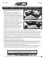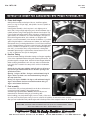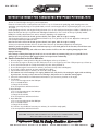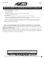
1
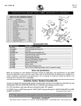
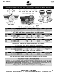
No.1972-IS
Rev NC
11/06
Instruction Sheet for Carbureted EVO Press Flywheel Kits
carbureted evo press flywheel kits
Use on 1970 - 1984 Shovelhead or 1984 – 1999 Evolution
These instruction are for the following part numbers:
1972,1973,1974,1976,1977,1978, 1979,1980,1981,1982,1983,1984,1985,1986,1987.
Read all instructions before performing any of this installation.
If you are not a qualified professional mechanic or equivalent then do not attempt to perform this installation. You are responsible for
the safety and quality of your work. If this installation is performed in an unsafe or unprofessional way then this could cause major damage or affect the safe operation of this motorcycle. Including but not limited to bodily injury or death. Take it to a qualified motorcycle
repair shop if you are not sure.
The following are for Carburated Evo Stroker Kits
with piston sets:
No.1976 - Use on 1984-99 Big Twin single cam motors. 4 -1/4” Stroke x 8 -1/2” O.D.
With STD bore 3 -1/2” pistons, for the shown assembly to build an 80”.
The compression ratio is approximately 10:1; depending on the CC size of the
combustion chamber in the heads being used with these pistons, also the
thickness of both the head and base gaskets.
No.1977 - With +. 005 over size, 3 -1/2” pistons, for above assembly.
No.1978 - With +. 010 over size, 3 -1/2” pistons, for above assembly.
No.1979 - Use on 1984-99 Big Twin single cam motors. 4-1/2” Stroke x 8 -1/2” O.D.
With STD bore 3 -1/2” pistons, for the shown assembly to build an 87”.
The compression ratio is approximately 10:1; depending on C the C size of the
combustion chamber in the heads being used with these pistons, also the thickness
of both the head and base gaskets.
No.1980 - With +. 005 over size, 3 -1/2” pistons, for above assembly.
No.1981 - With +. 010 over size, 3 -1/2” pistons, for above assembly.
No.1982 - Use on 1984-99 Big Twin single cam motors. 4- 5/8” Stroke x 8 -1/2” O.D.
With STD bore 3 -1/2” pistons, for above assembly to build an 89”.
The compression ratio is approximately 9.25:1; depending on the CC size of the combustion chamber in the heads being used with
these pistons, also the thickness of both the head and base gaskets.
No.1983 - With +. 005 over size, 3 -1/2” pistons, for above assembly.
No.1984 - With +. 010 over size, 3 -1/2” pistons, for above assembly.
No.1985 - Use on 1984-99 Big Twin single cam motors. 4 - 5/8” Stroke x 8 -1/2” O.D.
With STD bore 3 - 5/8” pistons, for above assembly to build a 96”.
The compression ratio is approximately 9.75:1; depending on the CC size of the combustion chamber in the heads being used with
these pistons, also the thickness of both the head and base gaskets.
No.1986 - With +. 005 over size, 3 -5/8” pistons, for above assembly.
No.1987 - With +. 010 over size, 3 -5/8” pistons, for above assembly.
NOTE: All flywheel kits with or without pistons come with a .792” I.D. wrist pin bushing.
CAUTION: Wear safety glasses. Excessive force may damage parts!
See JIMS® catalog for Hundreds of top quality professional tools.
The last tools you will ever need to buy.
555 Dawson Drive, Camarillo, CA 93012 Phone 805-482-6913 • Fax 805-482-7422
1
No.1972-IS
Rev NC
11/06
Instruction Sheet for Carbureted EVO Press Flywheel Kits
Below is the list of Stroker Flywheel Assemblies Only (without pistons):
The engine builder must supply the pistons that go with the stroked flywheels you will be building. If installing in the following years
1970 to 1972, you, the engine builder, will need to replace the side-oiling pinion shaft bushing in the cam cover, JIMS reference
(No.25582-54/73 for side-oiling) with JIMS No.25582-80AB. You may also need to do some modification to the cam cover to use the
new end-oiling bushing. The new bushing will need to be line reamed with Jims tool No.94805-57, see JIMS catalog for other tools for
removing and installing bushing.
No.1972 - Use on 1970-99 Big Twin single cam motors, 4-1/4” Stroke x 8-1/2” O.D.
No.1973 - Use on 1970-99 Big Twin single cam motors, 4-1/2” Stroke x 8-1/2” O.D.
No.1974- Use on 1970-99 Big Twin single cam motors, 4-5/8” Stroke x 8-1/2” O.D.
Piston Weight Requirements for JIMS Strokers
Below is a list of total piston weights. Example: (906 grams to 938
grams is the weight of two pistons, two sets of rings, two wrist pins
and two wrist pin clips.)
If the total weight of the pistons you are supplying, weigh from
(906 to 938 grams) they can be used with any of the three flywheel
assembles listed above to give you a balance factor of approximately 60%.
An approximate 60% balance factor is best suited for higher RPM riding
(shifting at a higher RPM) or a lower gear ratio. An approximate 52% balance factor is
best suited for a little less RPM riding, or a little higher gear ratio.
To maintain a balance factor of approximately 60%, both pistons with rings, pins, and clips should weigh between 906 grams and
938 grams.
To maintain a balance factor of approximately 56%, both pistons with rings, pins, and clips should weigh between 1021 grams and
1051 grams.
To maintain a balance factor of approximately 52%, both pistons with rings, pins, and clips should weigh between 1136 grams and
1166 grams.
Recommended Tools
JIMS Part No.
Description
No.1276
No.1047TP
No.1048
No.39361-69
No.1710
No.1133
No.1746
No.97225-55
No.1709
No.1034
No.1006T
No.1236
No.1068
No.1409
No. 96710-TL
Wrist Pin Remover/ Installer
Crank Assembly Removing Tool, for F/W removal
Hard Cap, use with No.1047TP
Motor Sprocket Seal Installer Tool
Snap Ring Installer and Removal Tool
Ratcheting Snap Ring Pliers
Timken Bearing Simulator
Sprocket Shaft Bearing Installation Tool
Timken Bearing Remover Tool
Sprocket Shaft Holder
Engine Stand
Piston Ring Compressor Tool
Tune-A-Cam for degreeing breather valve & crankshaft endplay
Case Boring Tool (for the 3-5/8” to 3-13/16” bore cylinders)
Lap Tool, right case race
555 Dawson Drive, Camarillo, CA 93012 Phone 805-482-6913 • Fax 805-482-7422
2
No.1972-IS
Rev NC
11/06
Instruction Sheet for Carbureted EVO Press Flywheel Kits
NOTE: Please read this entire instruction sheet before and during the installation of these flywheels and
pistons.
NOTE: You must use a H-D® Service Manual for the installation of these flywheels.
WARNING: The rider’s safety depends on you performing this installation correctly.
WARNING: Always disconnect the ground (negative) cable at the battery, by not doing so could result in
death or serious personal injury.
WARNING: Always wear safety glasses over your eyes; always protect your hands and face when using any
cleaning materials.
WARNING: Gasoline is highly flammable and explosive; don’t smoke or have any open flames near any
flammable liquids.
JIMS is proud to introduce these improved Big Twin flywheels. These flywheels are not just a copycat flywheel with a different stroke,
but a flywheel redesigned and engineered for today's and future Harley-Davidson® Motorcycles.
JIMS Big Twin flywheels are manufactured from the finest American 4140 forged steel blanks; ideal for precision machining and product integrity. To further help in rod strength and lubrication, we have designed three grooves around both crankpin thrust faces into
the JIMS flywheels. With grooves machined into the flywheel thrust faces, we have eliminated the four grooves that are ground into
the rod itself. When grooves are ground into the rod itself, the rods become susceptible to cracking.
JIMS CONNECTING RODS ARE PRODUCED FROM FORGED 4340 AEROSPACE QUALITY STEEL.
Connecting rods at their finest. JIMS research and development
team looked into all other rods on the market to see which areas
needed improvement. JIMS connecting rods start out as forged
aerospace quality 4340 Chromoly steel blanks, and then are CNC
machined on the newest high tech mills available. Each rod is
heat-treated, magnafluxed, shot peened, and completely inspected with a hardness test. From there, each rod goes back into the
CNC mill to bore the rod race bores to the wrist pin bushing bores
to within .0003" of each other at a 32 bore finish for the best possible bushing and race adhesion. The wrist pin bushing oiling hole
has been optimized for better lubrication of wrist pins, and an
increase in the strength. JIMS chose “H-Beam” rods for stability
and strength, for both drag racing and street application, over the
standard “I-beam” rods. Although we realize that “H-beam” rods
are very difficult and time consuming to manufacture, JIMS believes it is well worth the extra effort. Each rod set has JIMS rod races and
wrist pin bushings installed and are fit to Harley-Davidson factory specifications.
JIMS has provided you with detailed information listing the applications and specifications of each JIMS stroker kit applicable to this
instruction sheet. Please refer to this information throughout your installation for critical component combinations and specifications.
Do not attempt to install your stroker kit without cross checking each component for compatibility.
CAUTION: Wear safety glasses. Excessive force may damage parts!
See JIMS® catalog for Hundreds of top quality professional tools.
The last tools you will ever need to buy.
555 Dawson Drive, Camarillo, CA 93012 Phone 805-482-6913 • Fax 805-482-7422
3
No.1972-IS
Rev NC
11/06
Instruction Sheet for Carbureted EVO Press Flywheel Kits
For engine removal follow the instructions in H-D Service Manual.
Follow the disassembly instructions in the service manual to disassemble engine. Clean all parts thoroughly; make sure to clean all
gasket and mounting surfaces. Inspect all parts for visible damage. Measure all parts for wear using the “service wear limit section” in
the H-D Service Manual. Check and repair all threaded holes. Replace or repair all worn or damaged parts with JIMS engine parts or
equivalent.
Pinion Side Fitment.
These kits are shipped with standard length sprocket and pinion shaft (pinion shaft similar to Jims No.2437,) to be installed into
1970 -1999 cases with standard pinion shaft races (24599-58, 24599-58A, 24599-58B, etc.) JIMS No.24628-87 Green size pinion
bearings may also be used, see JIMS catalog for other over size pinion shaft bearing sets. Use JIMS No.2481K pinion bearing retainer,
(to retain pinion bearing to shaft.)
Note: Follow your H-D Service Manual for fitment of pinion bearings.
Use Jims tool No.96710-TL to lap case to fit pinion bearings.
For 3- 5/8” to 3 -13/16” bore pistons and cylinders, you will need to bore the engine cases to except the bigger cylinders. Use JIMS
No.1409 Case Boring Tool (for the 3- 5/8” to 3 -13/16” bore cylinders.)
For 1990-99 motors, use JIMS pinion gear No.24043-78, JIMS oil pump drive gear No.26349-84 (with JIMS keys 2480) and JIMS nut
No.24023-54.
For these flywheel assemblies, you will need to use JIMS pinion gear No.24043-78 as a starting point for cam gear fit to pinion gear fit
use JIMS pinion gear spacer No.24703-54B with oil pump drive gear No.26349-84.
Instructions: preparing the engine cases for JIMS new stroker flywheels.
1. Check cylinder studs and deck surfaces for flatness and any imperfections:
Clean and wash cases, give special attention to the cases mating
surfaces and assemble without flywheels. Install and torque all
case bolts to H-D Service Manuals specs.
Note: Take a measurement of stud height before removing.
Caution: Some studs may need heat to remove, do not over
heat, 210 degrees max.
Check cylinder base gasket surface. Use a straight edge across the
deck. See Fig 1. If any misalignment is present, the surface must
be milled.
Cover all areas where chips could get into. Take off just enough
case material to clean up the surface. Check all cylinder studs and
stud-threaded holes. If threads are damaged use JIMS tool
No.1000A to repair. JIMS suggests using the latest cylinder studs
available from Harley-Davidson, No.16837-95C. Follow instructions in H-D Service Manual for proper installation of studs.
FIG 1
2. Checking flywheel clearance to right case.
All stroker flywheels must be checked for having a clearance of no less then .060” to the complete inside of the left and right engine case.
With the old or new Timken bearing races installed in the left case and a new Timken bearing cone installed on sprocket shaft, use
JIMS tool No.97225-55 and following your H/D service manual to install the bearing cone on the new flywheel assembly. With small
pieces of molding clay pressed over any and all high places on the inside of left case (molding clay needs be at least .100” thick.)
See Fig 2, next page.
CAUTION: Wear safety glasses. Excessive force may damage parts!
See JIMS® catalog for Hundreds of top quality professional tools.
The last tools you will ever need to buy.
555 Dawson Drive, Camarillo, CA 93012 Phone 805-482-6913 • Fax 805-482-7422
4
No.1972-IS
Rev NC
11/06
Instruction Sheet for Carbureted EVO Press Flywheel Kits
Do not rotate the flywheels when performing this clay
check. Place the flywheel into the left case and hold in
FIG 2
place with JIMS No.1745 Timken Bearing Simulator. With
small pieces of molding clay pressed over any and all high
places on the inside of right case (molding clay needs be
at least .100” thick.)
Install old or new pinion bearing on pinion shaft and
install the right case over the flywheels and up to left case.
Apply
Note: You can use your old pinion shaft bearings for
clay
this clearance check; if you have already fit oversized
here
pinion bearings you may use them if the case race has
been completely cleaned of all lapping compound.
Do not rotate the flywheels when performing this
clay check.
Install and tighten at least 3 cases bolts to 10 lbs of
torque (lube all threads) to compress the clay, gently
remove case bolts and remove the right case from over
the flywheels also remove the flywheels from the left case.
Check all the compressed clay pieces for having no less
then .060” thickness at any location.
Example: From the top of the compressed clay (where the flywheel has compressed the clay) to the case surface on the right or
left case, this compressed clay must be at least .060” thick.
If one or more of the compressed clay pieces is less then .060” thickness you’ll need to remove the case material from those
places around the clay by the amount it is less by.
Example: If you have .040” you will need to remove approximately .020” of case material.
Remember to remove only enough material to maintain .060” from flywheel to case clearance.
Caution: A minimum of .060” clearance is required, be sure to mask off all bearing bores, oil holes and threaded holes,
before any case material is removed.
Do not remove any material from flywheels, shafts, bearings or rods.
If you are unsure as to whether or not you have at least .060” clearance, repeat the above clearance check until you are
sure of the clearance, for all of the high areas of both cases.
3. Connecting rod to case clearance.
To accurately check the necessary rod to case clearance, you will need to mock up the flywheel assembly into the left side case by
uising JIMS No.1745 Timken Bearing Simulator, same as above.
Note: Fitting pistons to cylinders for a running clearance will need to be completed before any rod to case clearance
check can be performed.
The pistons in this kit need to be fit to the cylinders using the specifications provided with pistons.
Note: Make sure cylinders have been washed, before installing pistons when checking rod clearance.
With flywheel assembly simulated in left case, (using JIMS No.1745 Timken Bearing Simulator) install pistons without rings and
place both cylinders and pistons on left case with 2 nuts and a short piece of rubber hose to hold cylinders down. Base gaskets
are not needed for this test.
CAUTION: Wear safety glasses. Excessive force may damage parts!
See JIMS® catalog for Hundreds of top quality professional tools.
The last tools you will ever need to buy.
555 Dawson Drive, Camarillo, CA 93012 Phone 805-482-6913 • Fax 805-482-7422
5
No.1972-IS
Rev NC
11/06
Instruction Sheet for Carbureted EVO Press Flywheel Kits
Note: Apply a small amount of lube (assembly oil or motor
FIG 3
oil) to piston skirts before installing in a clean and dry
cylinder.
Note: You may install one of the pistons wrist pin locks in
each piston to hold the wrist pin from falling out.
Caution: Make sure pistons are installed properly. The beveled
cut out on the cylinders spigot must point towards (face each
other) the center of the engine. Note: Some JIMS piston sets are
directional. Please align engraved (or laser marked) arrow on piston crown (top of piston) to the intake valve unless otherwise
noted. If using pistons other than JIMS, consult piston manufacturer’s installation instructions for proper alignment.
Rotate flywheels slowly, first clockwise watching for the rods or
pistons making contact with each other or any part of the cases,
FIG 4
see Fig 3. With felt pen mark the point of contact that rod makes
at case (Note: if rod makes contact with cylinder spigot, first,
mark point of contact of rod to spigot with felt pen).
Caution: Before removing any material remove flywheel
assembly and cover to keep out all chips and also mask all
bearing bores, oil holes and threaded holes of both cases.
Grind and file cylinder for a minimum of .100 ± .025, rod
clearance.
Caution: When grinding and filing cylinder, you must maintain a smooth finish, without making sharp corners.
Rotate flywheels counterclockwise, see Fig 4. With felt pen mark the point of contact the rod first makes at case. With a straight
edge mark a line from the marked point of rod contact to the other marked point of rod contact. With your calipers set at .100,
mark a line to the outside of the first line. This is the area you will be removing for rod clearance. Note: This .100 line is added in
for the necessary rod to the case clearance. Do the front rod clearance the same way. Caution: Before removing any material
remove flywheel assembly and cover, also mask off all bearing bores, oil holes and threaded holes of both cases. After you have
rechecked clearance of the left case (for the necessary .100 rod to case clearance) and cylinder spigots, remove cylinders, pistons
and flywheels from left case. Mark and remove material from right case to match left case. Caution: Before removing any material
remove flywheel assembly, cover and mask all bearing bores, oil holes, and threaded holes of both cases. Recheck your clearance
for right case by installing flywheels, both cylinders and pistons.
4. Piston to piston and piston’s skirt to flywheel clearance.
With the flywheel assembly mocked up in left case only, install cylinders and pistons, (no rings on the pistons as before). Make
sure they are installed properly. The beveled cut away on the cylinder base points towards the center of the engine. Securely
install the cylinders with (2) nuts on each cylinder. Rotate flywheel assembly slowly until pistons make contact with each other (or
just start to pass by each other.) See fig 5. A minimum of .100” clearance is required for the pistons to clear eachother.
Note: All material removal to be done on the rear intake side of piston only.
Caution: When grinding and filing the rear piston you must maintain a smooth finish without making sharp corners.
Remove only enough to make the .100” clearance. After piston-to-piston clearance is performed rotate flywheel and check piston
to flywheel clearance. Remove piston and or pistons and clearance skirt to a .100” minimum clearance. See fig 6.
CAUTION: Wear safety glasses. Excessive force may damage parts!
See JIMS® catalog for Hundreds of top quality professional tools.
The last tools you will ever need to buy.
555 Dawson Drive, Camarillo, CA 93012 Phone 805-482-6913 • Fax 805-482-7422
6
No.1972-IS
Rev NC
11/06
Instruction Sheet for Carbureted EVO Press Flywheel Kits
5. Piston deck height
With flywheel assembly mocked up in left case, install base gaskets,
pistons (no rings or wrist pin clips), and cylinders. Secure to cylinders as
stated previously.
Rotate flywheel assembly so the front piston is at its highest point of
travel (TDC). Using a straight edge laying across the bore diameter (top of
cylinder) measure (using a feeler gauge) the distance from the piston top
to the cylinder head gasket surface. (Note: If the piston is higher than the
gasket surface, this is referred to as "Positive Deck Height", if the piston is
below the head gasket surface, this is referred to as "Negative Deck
Height", note this measurement.) Now measure the thickness of your head
gasket using dial calipers or a micrometer and subtract your deck height
measurement from your head gasket thickness. You must have a minimum
of .043" clearance between your piston top and the top of the head gasket
when it is installed on the cylinder. If you have too little deck height (less
than .043") you can adjust this by using a thicker base or head gasket.
Remember optimal range for a performance oriented street motor is .043”
to .060” of deck below the top of the head gasket.
FIG 5
FIG 6
6. Breather Timing
JIMS recommends checking the breather timing on all engines regardless
of the stroke. Optimized breather timing will maximize performance. This
procedure requires a degree wheel. Use JIMS No.1068 Degree Wheel Kit.
When modifying the breather hole in the case, make sure the breather
hole in the case is located in the same position as hole in the breather.
See Fig 7.
Caution: Before doing any grinding, mask off and cover all areas to
keep out foreign material. Grind the case breather opening to the
specifications below:
Opening - 0 degrees @ TDC ± 10 degrees with minimum being 10
degrees before top dead center and maximum being 10 degrees
after top dead center.
Closing - 65 degrees @ ABDC ± 10 degrees with minimum being 55
degrees after bottom dead center and with maximum being 75
degrees after bottom dead center.
FIG 7
7. Final assembly.
Be sure all the work you have performed, from the above information is
correct, before final assembly of the complete engine.
Assemble engine per H-D Service Manual, make sure all parts are
cleaned and also checked for being in good working order.
Before installing your newly rebuilt engine, remove oil tank, oil lines and
oil cooler, wash out all these parts until you can run a clean cloth inside the oil tank and it comes out clean.
After you have installed this newly rebuilt engine and hooked up all the oil lines except the return oil, fill oil tank with proper
CAUTION: Wear safety glasses. Excessive force may damage parts!
See JIMS® catalog for Hundreds of top quality professional tools.
The last tools you will ever need to buy.
555 Dawson Drive, Camarillo, CA 93012 Phone 805-482-6913 • Fax 805-482-7422
7
No.1972-IS
Rev NC
11/06
Instruction Sheet for Carbureted EVO Press Flywheel Kits
amount of oil and the right viscosity for your air temperature.
Direct the oil return line into a catch-pan that can hold 2 to 3 qts of oil. Remove the spark plug, attach the plug wires to the
spark plugs, ground (spark plugs) on the cylinder heads, and turn over the engine until the oil presure light goes out or you have
10 –15 psi.
Install spark plugs and wires, start engine allowing the return oil to run into catch–pan. Run engine at 1000 to 1500 RPM (do not
blip the throttle) until the tops of cylinders reach 200 degrees Fahrenheit (too hot to touch at the top of cylinders, not the
heads) this normally takes between one and two minutes, depending on air temperature.
Note: Do not let the oil level in oil tank get lower than 3/4 of a quart, while the engine is running.
Stop the engine and let it cool to room temperature. Check for any oil or gas leaks, top-off oil tank. Repeat the warm up and
cool-down procedure three additional times.
Note: Do not let the oil level in oil tank get lower than 3/4 of a quart, while the engine is running.
You may now reconnect the return oil line to oil tank after at least two qts have been pumped into the catch-pan.
Caution: If you do not perform the above initial start up steps, to seat head gaskets for the first time, this will often cause
premature head gasket failure.
These break in instructions may take a little more time now but is still less time than replacing damaged parts from
improper start ups.
Note: Damage resulting from improper break in is not covered under any warranty. Only you are responsible for the
quality of the job you perform. JIMS cannot be liable for inexperienced workmanship.
8. Break in Procedure for the first 2000 miles.
1.
2.
3.
4.
5.
6.
7.
Allow the engine to warm-up before riding (about 200 degrees at the top of cylinders.)
Do not allow the engine to idle any lower then 1000 rpm, also do not rev engine any more then 1500 rpm upon any cold start up.
Do not use full throttle and do not blip the throttle at any time during the break in.
Do not idle the engine for more than two minutes, (less time if air temp is above 80-degrees)
Do not load or lug the engine at any time, (especially at low RPM)
Vary the RPM at least every two minutes, (do not hold a steady speed)
Use common sense when running a new engine, NO burn-outs, No wheelies, No running the engine with out it being
in perfect-tune. You may see those morons on TV doing it, but you’ll never see that bike running again.
8. Follow H-D Service Manual for all maintenance information as you continue to put miles on this engine.
9. First 50 miles.
a. Do not rev the engine more then 2500 rpm
b. Do not exceed 50 MPH
c. Change the oil and filter
d. See re-torque Notes and Cautions below
10. Next 500 miles
a. Do not rev the engine more then 3000 rpm
b. Do not exceed 55 MPH.
c. Change the oil and filter
d. See re-torque Notes and Cautions below
11. Next 1000 miles
a. Do not rev the engine more then 4000 rpm
b. Do not exceed 65 MPH
c. Change the oil and filter
d. Continue to vary the RPM at least every two minutes, (do not hold a steady speed)
e. See re-torque Notes and Cautions below
CAUTION: Wear safety glasses. Excessive force may damage parts!
See JIMS® catalog for Hundreds of top quality professional tools.
The last tools you will ever need to buy.
555 Dawson Drive, Camarillo, CA 93012 Phone 805-482-6913 • Fax 805-482-7422
8
No.1972-IS
Rev NC
11/06
Instruction Sheet for Carbureted EVO Press Flywheel Kits
12. Next 1500 to 2000 miles
a. Do not rev the engine more then 4000 rpm
b. Do not exceed 65 MPH
c. Change the oil and filter
d. Continue to vary the RPM at least every two minutes, (do not hold a steadyspeed)
e. See re-torque Notes and Cautions below
13. Re-torque fasteners
Note: Re-torque, Re-check the torque on all engine and chassis fasteners at each oil and filter change.
Caution: Do not re-torque head bolts on EVO engines, If the engine is a Shovel head, re-torquing of the head and base nuts
and bolts will need to be performed after the first running and cool down of engine.
Note: Only re-torque head bolts and base nuts after the engine has cooled down after running, the re-torque should be per
formed two to three times in the first 50 miles until the bolts or nuts do not move under the maximum torque setting.
Thanks for using the best, JIMS, and have fun.
JIMS® IS NOT RESPONSIBLE FOR THE QUALITY AND SAFETY OF YOUR WORK!
If you are not sure about any of the procedures in these instructions, have a reputable H.D. repair shop
perform these procedures for you.
WARNING: Always disconnect the Battery Ground Cable (at the battery) to prevent injury. Your work area should be well lit. Wear
safety glasses (over your eyes) and protective clothing when working around power tools and compressed air. Be careful with
chemicals when cleaning parts. Protect your skin from solvents and use only in a well-ventilated area. Degreasers are flammable and
are a fire hazard. Just use common sense and exercise good judgement.
CAUTION: Wear safety glasses. Excessive force may damage parts!
See JIMS® catalog for Hundreds of top quality professional tools.
The last tools you will ever need to buy.
555 Dawson Drive, Camarillo, CA 93012 Phone 805-482-6913 • Fax 805-482-7422
9