1
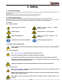
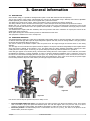
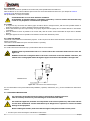
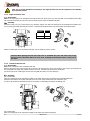
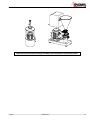
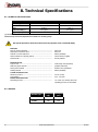
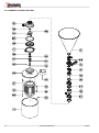
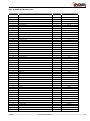
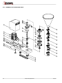
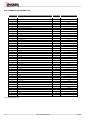
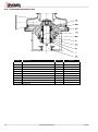
INSTALLATION, SERVICE AND MAINTENANCE INSTRUCTIONS BLENDER 226 / 440 INOXPA, S.A. c/Telers, 54 Aptdo. 174 E-17820 Banyoles - Girona (Spain) Tel. : (34) 972 - 57 52 00 Fax. : (34) 972 - 57 55 02 Email: [email protected] www.inoxpa.com Original manual 02.002.30.00EN (B) 2014/09 EC Declaration of Conformity The manufacturer: INOXPA, S.A. c/ Telers, 57 17820 Banyoles (Girona), Spain herewith declares that the machine: Blender M-226 / M-440 with the serial number: ________________ conforms to the relevant provisions of the following directives: Machinery Directive 2006/42/EC (RD 1644/2008) Low voltage Directive 2006/95/EC Electromagnetic Compatibility Directive 2004/108/EC Applicable harmonised Standards: UNE-EN ISO 12100:2012 Identification of the person empowered to draw up the Declaration on behalf of the manufacturer, and qualified to compile the technical file established by the Community: Banyoles, 8 January 2014 David Reyero Brunet Technical Office Manager 1. Safety 1.1. INSTRUCTIONS MANUAL This manual contains information on the reception, installation, operation, assembly, dismantling and maintenance of the INOXPA blenders. The information published in the instruction manual is based on updated information. INOXPA reserves the right to modify this instruction manual without prior notice. 1.2. START-UP INSTRUCTIONS This instruction manual contains vital and useful information to appropriately handle and maintain your blender. Read these instructions carefully before starting up the blender; become familiar with the operation and use of your blender and follow the instructions closely. These instructions should be kept in a safe location near the installation. 1.3. SAFETY 1.3.1. Warning symbols Danger for persons in general Danger of injury equipment parts. caused by rotating Electrical danger Danger! Caustic or corrosive agents. Danger! Suspended loads Danger to the correct operation of the equipment. Commitment to safety at the workplace. Protective goggles requirement. 1.4. GENERAL SAFETY INSTRUCTIONS Read carefully this instruction manual before installing and starting the blender. Contact INOXPA in case of doubt. 1.4.1. During installation The Technical Specifications of Chapter 8 should always be observed. Never start up the blender before it has been connected to the tubing. Do not start up the blender if the cover has been removed and the impeller is fixed to the blender. Check that the motor specifications meet the requirements, especially when working under conditions that involve the risk of explosion. During the installation, all the electric work should be carried out by authorised personnel. 1.4.2. During operation The Technical Specifications of Chapter 8 should always be observed. Under no circumstances can the limit values specified be exceeded. NEVER touch the blender or the pipes during operation when the blender is being used to decant hot fluids or when it is being cleaned. The blender contains moving parts. Never place your fingers inside the blender while it is in operation. 2014/09 1.Safety 3 NEVER operate the pump with the suction and delivery valves closed. NEVER spray the electrical motor directly with water. The standard protection for the motor is IP-55: Protection against dust and sprayed water. 1.4.3. During maintenance The Technical Specifications of Chapter 8 should always be observed. NEVER disassemble the blender until the pipes have been emptied. Remember that some of the fluid will always remain in the blender housing (when no drainage is provided). Note that the pumped fluid may be dangerous or very hot. Consult the regulations in effect in each country for these cases. Do not leave parts loose on the floor. ALWAYS disconnect the blender from the power supply before starting maintenance work. Remove the fuses and disconnect the cables from the motor terminals. All electrical work should be carried out by authorised personnel. 1.4.4. Compliance with the instructions Any non-fulfilment of the instructions may result in a risk for the operators, the environment and the machine, and may result in the loss of your right to claim damages. This non-fulfilment may result in the following risks: Failure of important functions of the machines/plant. Failure of specific maintenance and repair procedures. Possibility of electric, mechanical and chemical risks. Will place the environment in danger due to the release of substances. 1.4.5. Guarantee Any warranty provided shall immediately be cancelled and void ipso jure, and INOXPA shall be compensated for any product liability claim from third parties, if: the service and maintenance work was not carried out in accordance with the service instructions, or the repair work has not been carried out by our personnel or it has been conducted without our written authorization; our equipment has been changed without prior written authorization; the parts or lubricants used are not original INOXPA parts and products; the materials were used incorrectly or negligently, or not in accordance with these instructions and their intended use; blender parts were damaged by excessive pressure owing to the lack of a safety valve. The General Delivery Terms already provided also apply. No change can be made to the equipment without prior discussion with the manufacturer. For your safety, please use original spare parts and accessories. The use of other parts will exempt the manufacturer from any liability. The service terms can only be changed with prior written authorisation from INOXPA. Please do not hesitate to contact us in case of doubts or more complete explanations are required on specific data (adjustments, assembly, disassembly, etc.). 4 1.Safety 2014/09 2. Table of Contents 1. Safety 1.1. INSTRUCTIONS Manual ................................................................................................. 3 1.2. Start-up instructions ...................................................................................................... 3 1.3. Safety .......................................................................................................................... 3 1.4. GENERAL SAFETY INSTRUCTIONS .................................................................................. 3 2. Table of Contents 3. General information 3.1. Description ................................................................................................................... 7 3.2. OPERATING Principle ..................................................................................................... 7 3.3. PRODUCTS TO BE AVOIDED .......................................................................................... 8 3.4. Application ................................................................................................................... 8 4. Installation 4.1. RECEIVING THE BLENDER ............................................................................................. 9 4.2. TRANSPORT AND STORAGE ........................................................................................... 9 4.3. Location ..................................................................................................................... 10 4.4. pipes .......................................................................................................................... 10 4.5. Shut-off valves ............................................................................................................ 10 4.6. PRESSURISATION TANK .............................................................................................. 10 4.7. Electrical installation .................................................................................................... 10 5. Start-up 5.1. Start-up ..................................................................................................................... 12 6. Operating Problems 7. Maintenance 7.1. General information ..................................................................................................... 14 7.2. Storage ...................................................................................................................... 14 7.3. Cleaning ..................................................................................................................... 14 7.4. DISASSEMBLY / ASSEMBLY OF THE blender. ................................................................. 15 8. Technical Specifications 8.1. Technical Specifications ............................................................................................... 20 8.2. WEIGHTS ................................................................................................................... 20 8.3. BLENDER M-226 DIMENSIONS ..................................................................................... 21 8.4. BLENDER M-440 DIMENSIONS ..................................................................................... 21 8.5. BLENDER M-226 EXPLODED VIEW ................................................................................ 22 8.6. BLENDER 226 CROSS-SECTION .................................................................................... 23 8.7. BLENDER 226 PARTS LIST ........................................................................................... 24 8.8. BLENDER M-440 EXPLODED VIEW ................................................................................ 25 8.9. BLENDER M-440 CROSS-SECTION ................................................................................ 26 8.10. BLENDER M-440 PARTS LIST ...................................................................................... 27 8.11. BLENDER M-226 CP Exploded View ............................................................................. 28 2014/09 2.Table of Contents 5 8.12. BLENDER M-226 CP Cross-Section ...............................................................................29 8.13. BLENDER M-226 CP Parts List ......................................................................................30 8.14. BLENDER M-226 COOLED MECHANICAL SEAL ...............................................................31 8.15. BLENDER M-440 COOLED MECHANICAL SEAL ...............................................................31 8.16. M-440 DOUBLE MECHANICAL SEAL..............................................................................32 6 2.Table of Contents 2014/09 3. General information 3.1. DESCRIPTION In the blender design, it is possible to distinguish three parts or areas that define its build and operation. The top part consists of the hopper, solid-material area, and we can add powder using a butterfly valve with an adjustable handle. Optionally, the butterfly valve can be supplied with a pneumatic actuator. The middle area consists of the venturi, which is the blender's suction, and where the liquid is introduced. The mixing chamber, which is located in the bottom part, is where the liquid meets the powder and produces the mixture. Blender 226 is of a compact design, with the hydraulic part joined to the motor, and clamp-type connections. In the M-440 model, the hydraulic part and the motor are separate and mounted on a baseplate. Transmission is through pulleys mounted beneath the baseplate. The standard motor complies with IEC standards, with IP-55 protection and class F insulation. On request, the motors can be supplied with other protections. All the parts entering into contact with the product are manufactured in AIS 316L. This equipment is suitable for his use in food process. 3.2. OPERATING PRINCIPLE The blender basically consists of a casing and a centrifugal-pump impeller which are mounted vertically. The suction consists of an annular double-wall pipe that keeps the liquid and powder separate until they enter the mixing chamber. This pipe prevents the powder from becoming damp (see figure 3.1). The suction created by the blender impeller sucks the powder from the hopper through the internal venturi to the mixing chamber. The other pipe is used to introduce the liquid towards the impeller. The liquid is introduced tangentially into the impeller blades where the pressure gradient of the blender is zero. The liquid enters the mixing chamber tangentially, following the same rotating direction as the impeller. In this way, the powder-inlet pipe remains dry while the blender is in operation. If the inlet pipe appears to be blocked, firstly, check that the rotating direction of the impeller is correct and then, check that the distribution assembly is correctly assembled. In order to check the distributor installation, draw a continuous arrow from the inlet to the outlet without changing direction (see figure 3.2). During normal operation, a vortex is formed in the centre of the impeller, sucking the powder through the internal venturi and remaining dry. If the vortex is not formed, the powder might become damp and flocs may form in the mixture; the inlet pipe might even become blocked. Correct Incorrect Figure 3.2 Figure 3.1 Here are the reasons why the powder may become damp or wet: Incorrect liquid-intake flow rate A very high flow rate and/or pressure may destroy the blender vortex, and it would then not be able to pump the liquid with sufficient speed. This can also happen with a very low flow rate, as it causes powder to accumulate on the impeller, thus making it impossible to create the vortex in the centre of the impeller. Incorrect pressure. The differential pressure of the blender must be low (6-9 m), the same as the pressure at the blender intake, which must negative. 2014/09 3.General information 7 High viscosity. A viscous product naturally causes counterpressure. Adding this to the counterpressure caused by the grille, leads to very high pressure. It is advisable to remove the grille, which is an optional part, when highly viscous products need to be mixed. High delivery pressure. If the delivery piping is too long or its diameter is too small, or viscosity is very high, a very high counterpressure will be caused. In order to resolve these problems, the piping must be of correct dimensions, or if necessary, a pump must be fitted to the blender outlet. It may be a centrifugal pump, but its pumping capacity is limited if maximum mixture yield is required. If counterpressure increases in the blender, the vortex diminishes thus reducing the mixing capacity of the solid and liquid ingredients. It is also important to maintain negative pressure at the blender intake. The amount of powder that can be added is very difficult to define, as a great number of variables are involved. Some of these variables are particularly important, such as: Dampness Fatty material content Microscopic texture (smooth, rough). Density Fluidity (air volume in the product) Powder type (granular, flaky, fines, etc.) The amount of powder that can be dissolved in the blender depends on the characteristics of the product. 3.3. PRODUCTS TO BE AVOIDED Abrasives: These products deteriorate the mechanical seals and impellers. Effervescents: The gas that these produce prevents the vacuum from forming and the powder from falling from the hopper. High temperatures: It is not advised to work at 65 oC, as vapours may be given off that may cause the venturi to be blocked. This may also cause cavitation in the blender as it approaches boiling point. Very high viscosities: The blenders cannot pump highly viscous products. The maximum viscosity of the blenders is 250 cPs. Incompatible products: Products incompatible with the various mechanical seals and elastomers. 3.4. APPLICATION M-226/440 blenders can be used in any process where powder is added first and is then dissolved in liquid. Examples: Powdered milk. Whey. Chocolates. Sauces. Brines. Fertilisers. Lactose. Stabilisers, mixtures with milk. Pesticides, etc. 8 3.General information 2014/09 4. Installation 4.1. RECEIVING THE BLENDER INOXPA cannot be held responsible for the damage sustained by the equipment during transport or unpacking. Visually check that the packaging is not damaged. The blender will be accompanied by the following documents: Dispatch notes. Blender Instructions and Service Manual. Motor Instructions and Service Manual (*) (*) when the blender is supplied with a motor by INOXPA. Unpack the blender and check: The blender hopper suction and delivery connections, removing the remains of any packaging materials. Check that the blender and the motor have not suffered any damage. If the equipment is not in good condition and/or any part is missing, the carrier should draw up a report accordingly as soon as possible. 4.1.1. Blender identification Serial number Blender plate 4.2. TRANSPORT AND STORAGE The blenders are often too heavy to be handled and stored manually. Lift the blender as shown below: 2014/09 4.Installation 9 4.3. LOCATION Place the blender as close as possible to the suction tank, and if possible below the fluid level. Place the blender so as to allow sufficient space around it to access the blender and the motor. (See Chapter 8 Technical Specifications for dimensions and weight). Set up the blender on a flat, level surface. Install the blender so as to allow sufficient ventilation. If the blender is installed outdoors, it should be protected by a roof. Its location should enable easy access for any inspection or maintenance operations. 4.4. PIPES As a general rule, the suction and delivery pipes should be fitted in straight sections, with the least possible number of bends and accessories, in order to minimise head loss caused by friction. Ensure that blender input and output fittings are properly aligned with the piping and of a similar diameter to the blender connections. Place the blender as close as possible to the suction tank, with the suction nozzle underneath the liquid level to facilitate priming. Place pipe supports as close as possible to the blender’s suction inlet and delivery outlet. 4.5. SHUT-OFF VALVES The blender can be isolated for maintenance purposes. To this end, shut-off valves should be fitted to the blender's suction and delivery connections. These valves should ALWAYS be open when the blender is operating. 4.6. PRESSURISATION TANK For models with a dual mechanical seal, a pressurisation tank has to be installed. ALWAYS install a pressurisation tank 1 to 2 meters above the connection shaft below the seal. See Figure 4.6. 1...2m ALWAYS connect the cooling fluid inlet to the lower connection of the seal chamber. Therefore, the outflow of the cooling liquid will be through the upper connection of the chamber. See Figure 4.6. Mechanical seal Cierre mecánico Figure 4.6: Pressurisation tank installation diagram For more information on the pressurisation tank (installation, operation, maintenance, etc.), see the manufacturer’s instructions manual. 4.7. ELECTRICAL INSTALLATION The connection of the electrical motors must be performed by qualified personnel. Take all necessary measures to prevent damage to connections and cables. The electrical equipment, terminals and components of the control systems may still contain electric current when switched off. Contact with them may be dangerous for operators or cause irreversible damage to the equipment. Before handling the blender, make sure that the engine is fully disconnected from the power. Connect up the motor following the manufacturer’s instructions. 10 4.Installation 2014/09 Check the direction of rotation (see the label on the blender). Start up the blender motor briefly. Looking at the blenders from the hopper side, check that the motor fan rotates anti-clockwise. ALWAYS check the direction of rotation of engine with fluid inside the blender. For models with a seal chamber, ALWAYS make sure that the chamber is full of fluid before checking the rotation direction. 2014/09 4.Installation 11 5. Start-up Before starting the blender, carefully read the instructions provided in Chapter 4. Installation. 5.1. START-UP Read Chapter 8 Technical Specification carefully. INOXPA cannot be held responsible for the incorrect use of the equipment. NEVER touch the blender or the pipes when hot fluid is being pumped. 5.1.1. Checks before starting up the blender Fully open the shut-off valves on the suction and delivery pipes. If the fluid does not flow into the blender, fill it with the fluid to be pumped. The blender must NEVER be run dry. Check that the motor’s direction of rotation is correct. Check that the impeller rotates without scraping, taking into account the mechanical seals and the transmission belts (in M440). If the blender has a double seal or a cooled mechanical seal, mount the auxiliary connection corresponding to the values indicated in Chapter 8 Technical Specification. 5.1.2. Checks when starting up the blender Check Check Check Check that the blender is not making any unusual noises. whether the absolute inlet pressure is enough to avoid cavitation in the blender. the flow pressure. that there are no leaks through the sealed areas. A shut-off valve on the suction pipe must not be used to regulate flow. Shut-off valves must be fully open during operation. Check the motor’s power consumption to avoid electric overload. 12 5.Start-up 2014/09 6. Operating Problems The following table provides solutions to problems that might arise during blender operation. The blender is assumed to have been properly installed and correctly selected for the application. Please contact INOXPA if technical assistance is required. Operating Problems Probable causes No suction. Insufficient pressure on delivery. Motor overload Noise. Vibrations. Leaks. 1, 2, 3, 4, 5, 6, 7. 8, 9 10, 11, 12 13, 14. 15, 16, 17 17, 18, 19, 20 6, 7, 21, 22, 23 Probable causes Solutions 1 Pump supply incorrect. 2 3 Wrong direction of rotation Distribution assembly not properly assembled. 4 5 6 7 Very high powder proportion. Excessive temperature. Leak in delivery pump suction. Worn mechanical seal. 8 9 Differential pressure too high Suction pressure too high 10 11 12 13 14 15 Solids proportion too high to work with mesh. Insufficient liquid. Highly viscous product or delivery height too high. Solids proportion too high to mix with mesh. High solids proportion. Worn motor bearings. 16 17 Worn blender bearings. Foreign bodies inside the blender. 18 19 20 21 22 23 The blender is not at the right level. The impeller has been damaged. Blender cavitation. O-rings unsuitable for the fluid. The mechanical seal spring tension is too low Clamp is loose. Select the correct pump size for said application. See chapter 3. Reverse the motor rotation direction. Check and assemble the distribution assembly as instructed in chapter 8. See chapter 3. Reduce temperature Check the suction pipe and all its connections Replace the mechanical seal of the blender and/or the delivery pump. Reduce pressure. See chapter 3. Reduce suction pressure. It may be possible to stop using the delivery pump. See chapter 3. Remove the mesh. Check the delivery pump. Fit an extraction pump. Remove the mesh. Fit an extraction pump. Replace the bearings as indicated in the manufacturer's instructions manual. Replace bearings; review the blender. Disassemble the blender and remove the foreign bodies. Check the housing, impeller, and mechanical seal. Correct the blender level and alignment. Replace the impeller Reduce pressure drops on suction or use a delivery pump. Fit suitable O-rings after checking with the manufacturer. Adjust as indicated in this Manual Tighten the clamp. If the problems persist, stop using the blender immediately. Contact the blender manufacturer or its representative. 2014/09 6.Operating Problems 13 7. Maintenance 7.1. GENERAL INFORMATION Like any other machine, this blender requires maintenance. The instructions contained in this manual cover the identification and replacement of spare parts. The instructions have been prepared for maintenance personnel and for those responsible for the supply of spare parts. Please carefully read Chapter 8 Technical Specification. All replaced material should be duly eliminated/recycled according to the directives in effect in the area. ALWAYS disconnect the blender from the power supply before undertaking maintenance work. 7.1.1. Checking the mechanical seal Regularly check that there are no leaks in the shaft area. If there are leaks through the mechanical seal, replace it following the instructions given under the Assembly and Disassembly section. 7.2. STORAGE The blender must be completely emptied of fluid before storage. If possible, avoid exposing the components of the pump to excessively damp environments. 7.3. CLEANING The use of aggressive cleaning products such as caustic soda and nitric acid may cause burns to the skin. Use rubber gloves during the cleaning process. Always use protective goggles. 7.3.1 Limpieza CIP (Clean-in-place) If the blender is installed in a system with a CIP process, it is not necessary to dismantle the blender. If there is no automatic cleaning process, dismantle the blender as indicated in the Assembly and Disassembly section. Cleaning solutions for CIP processes. Only use clear water (chlorine-free) to mix with the cleaning agents: a) Alkaline solution: 1% by weight of caustic soda (NaOH) at 70ºC (150ºF) 1 Kg NaOH + 100 l. of water = cleaning solution or 2.2 l. NaOH at 33% + 100 l. of water = cleaning solution b) Acid solution: 0.5% by weight of nitric acid (HNO3) at 70ºC (150ºF) 0.7 litres HNO3 at 53% + 100 l. of water = cleaning solution Check the concentration of cleaning solutions; it may cause the deterioration of the watertight seals of the blender. To remove any remains of cleaning products, ALWAYS perform a final rinse with clean water on completion of the cleaning process. 14 7.Maintenance 2014/09 7.3.2 Automatic SIP (sterilization-in-place) The steam sterilisation process is applied to all equipment including the pump. DO NOT operate the equipment during the steam sterilisation process. The parts/materials will not suffer damage provided the instructions set out in this manual are followed. Cold liquid cannot be introduced until the pump temperature is below 60oC (140oF). The pump generates a substantial pressure loss through the sterilisation process; we recommend the use of a bypass circuit provided with a discharge valve to ensure that the steam / overheated water sterilises the entire circuit. Maximum conditions during the steam or overheated water SIP process a) b) c) d) Max. temperature: 140°C / 284°F Max. time: 30 min. Cooling: Sterilised air or inert gas Materials: EPDM / PTFE (recommended) FPM / NBR (not recommended) 7.4. DISASSEMBLY / ASSEMBLY OF THE BLENDER. Housing and impeller Disassembly Close the suction and delivery valves. Remove the parts of the top of the housing (01) in sequence: hopper (101), butterfly valve (96), distribution assembly (102) and internal venturi (103), removing the clamps (91, 91A) that connect the parts together. Remove the retention ring (15) Check that the O-ring (80A) is in good condition. Remove the housing (01). (for model M-226) Remove the screws (50A) and take out the motor shroud (14). Disassemble the fan protection of the drive according to the manufacturer's manual. Fix the motor fan shaft with a spanner taking care not to damage it, to prevent the blender shaft from rotating, and remove the screw fixing the impeller (25) and the O-ring (80D) with a box spanner. Remove the impeller (02). If necessary, give it a thud with a plastic hammer to remove the cone. (for model M-440) Remove the protector (47A). Place a fixed wrench in the shaft planes (05), to prevent rotation, and remove the impeller screw (25) and the O-ring (80D). Remove the impeller (02). If necessary, give it a thud with a plastic hammer to remove the cone. Assembly (for model M-226) Slide the impeller (02) over the shaft (05) until it touches the rotating part of the mechanical seal (08), fit the O-ring (80D) in the slot of the impeller screw (25) and tighten the screw in the impeller (21) using a box spanner and spanner on the shaft of the motor fan, taking care not to damage it, to prevent the shaft from rotating. (for model M-440) Slide the impeller (02) over the shaft (05) until it touches the rotating part of the mechanical seal (08), fit the O-ring (80D) in the slot of the impeller screw (25) and tighten the screw in the impeller (21) using a box spanner on it and a flat one in the interspace of the shaft milling. Fit the protector (47A) and fasten with the screws (50A). Mount the housing (01) and fasten it to the lantern (04) / bearings support (06) using the retention ring (15). Then fit the distribution assembly (102), the internal venturi (103) with the O-ring (80), the butterfly valve (96), and the hopper with their respective clamps (91, 91A) and clamp connections (91B, 91C). 2014/09 7.Maintenance 15 Take care to fit the distribution assembly in the right direction for smooth operation of the blender (see exploded views). 7.4.1. Single mechanical seal Disassembly Remove the rotary part of the mechanical seal (08). Remove the pump cover (03), the fixed part of the mechanical seal (08A) will remain housed inside the cap (10A). Remove the fixed part of the mechanical seal (08A). Assembly Mount the pump cover (03) on the lantern (04) / bearings support (06). Place the fixed part of the mechanical seal (08A) in the cover housing (03) taking the knob into account. Check that assembly measure used is that which is described below: Seal diameter A 1” 26 1½” 31 Slide the rotating part of the mechanical seal (08) over the shaft (05) until it touches. Caution! When placing the new seal, take care to assemble the parts and seals using soapy water to ensure that these slide over each other, including the fixed part and the rotary part of the shaft. 7.4.2. Cooled mechanical seal Disassembly Remove the rotary part of the mechanical seal (08). Remove the pump cover (03A) and the cap (1) that are still mounted (the cap is only present in the M-440); the fixed parts of the mechanical seals (08A, 08C) remain housed in the cover. Carefully remove these two fixed parts. Loosen the pins of the rotating part of the lower seal (08B) and slide it over the shaft (05). Assembly (for model M-226) Place the rotating part of the external seal (08B) on the shaft (05) and fix it according to the assembly dimension. Mount the fixed part of the external seal (08C) onto the cover (03A) and then this onto the lantern (04). In order to fit the internal mechanical seal, see the section on assembling the simple mechanical seal. (for model M-440) Place the rotating part of the external seal (08B) on the shaft (05) without fastening it. 16 7.Maintenance 2014/09 Place the O-ring (80C) over the seal cover alignment (03A). Place the cap (10) over this alignment and fasten it to the seal cover (03A) using hexagonal screws (52) and washers (53). Mount the fixed part of the external seal (08C) inside. Carefully fit this group over the bearings support alignment (06). Place the rotating part of the external seal (08B) until it touches the fixed part (08C) and fasten it with the pins. In order to fit the internal mechanical seal, see the section on assembling the simple mechanical seal. 7.4.3. Double mechanical seal Disassembly Remove the screws (52); now the cap of the double seal is loose (10). Remove the seal cover (03A), the fixed part of the internal mechanical seal (08B) will remain housed inside the cap (10). Loosen the pins (55A) and the pins of the seals' rotating parts and then remove those rotating parts of the mechanical seals (08B, 08C) from the shaft (05A) and the separator. Remove the double seal cap (10), the fixed part of the outside mechanical seal (08C) will remain housed inside the cover. Assembly Place the fixed part of the outside mechanical seal (08C) in its housing inside the cap of the double seal (10). Introduce the double seal cap (1), leaving it loose at the end of the shaft (05A). Slide the rotating part of the external mechanical seal (08C) and the separator (17B), and fasten it with the pins (55) according to the indicated assembly dimension. Mount the rotary part of the inside seal (08B) to the separator (17B). Place the fixed part of the inside seal (08B) into its housing inside the seal cover (03A). Mount the cover (03A) on the bearings support (06), previously fitting the O-ring (80C), and fastening it with the double seal cap (10) with the screws (52) and washers (53). 2014/09 7.Maintenance 17 7.4.4. Changing belts and pulleys Loosen the transmission belts (105) by screwing the two tightening screws (25A) in order to facilitate extraction of the belts. Remove the 3 belts (105). Remove the hexagonal screw (52C), washer (35), and pulley (104) from the bearings support side, and the hexagonal screw (52D), washer (35A), pulley stop bushing (17), and pulley (104A) from the motor side. The new fitted belts (105) must be correctly tightened. After a few hours of operation, check that they have not lost their tautness. Do not tighten the belts too much as this may damage the support and motor bearings. 7.4.5. Changing bearings Disassembly First disassemble according to the mechanical seal section and the changing belts and pulleys section. Remove the bearings support group from off the bedplate (38) by removing the hexagonal screws (52) and washers (53). Remove the elastic ring (66A) from beneath the lower bearing (70) using appropriate pliers. Remove the splash-ring (82, 82A). Remove the shaft (05) with the bearings still mounted beneath the support by gently knocking with a plastic hammer on the top of the shaft. Remove the elastic ring (66) and remove the two bearings (70) and separator (17A). Assembly Place the top bearing (70) on the shaft (05). Mount the separator (17A) and the second bearing, fixing the assembly with the elastic ring (66). Mount the shaft assembly with the bearings in the support (06) underneath, and fix it with the elastic ring (66A). Place the splash-ring (82, 82A) on the shaft (05). Mount the whole assembly on top of the bedplate (38) with the screws (52) and washers (53). 7.4.6. Changing the motor (for model M-226) Remove the splash-ring (82, 82A). Loosen the pins (55) and take out the shaft (05) from above. Remove the screws (50A) and take out the motor shroud (14). Remove the hexagonal screws (52) and washers (53) holding the motor (93) at the base of the lantern (04). Hold on to the motor at the same time so that it does not fall. Remove the motor from beneath the feet (07). (for model M-440) First disassemble according to the belts and pulleys section. Remove the screws (50A) and take out the motor shroud (14). Remove the hexagonal screws (52A, 52B) that are fixing the motor to the bedplate (38) and the tensioner platform (42). Remove the motor (93) with the help of slings due to its substantial weight. At the same time, hold the platform (42) down so that it does not lift with the motor. 18 7.Maintenance 2014/09 Replace the motor and motor bearings according to the manufacturer's instructions manual. 2014/09 7.Maintenance 19 8. Technical Specifications 8.1. TECHNICAL SPECIFICATIONS Blender model Blender engine Suction Drive Liquid flow Suction of solids (*) M-226 M-440 4 kW 3000 rpm. 11 kW 3000 rpm. CLAMP 1½” CLAMP 2” up to 33,000 litres/hour 3000 [kg/h] CLAMP 3” CLAMP 3” up to 65,000 litres/hour 9000 [kg/h] 45 litres 60 litres Hopper capacity (*) The amount of material taken in depends on the characteristics of the material Contact Inoxpa's technical department for selection of auxiliary pumps Use special protection when the noise level in the operation area exceeds 85 dB(A). Materials Parts in contact with fluid......................................................... Other parts in stainless steel. .................................................. Gaskets in contact with fluid ................................................... Other materials for optional gaskets ........................................ Surface finish ......................................................................... Mechanical seal Type of seal ......................................................................... Stationary parts material ....................................................... Rotary parts material ............................................................ Sealing material ................................................................... Cooled mechanical seal Maximum pressure ................................................................ Consumption ......................................................................... Double mechanical seal Operating pressure ................................................................ AISI 316L AISI 304 EPDM (standard) Check with the supplier Ra 0.8 polished inside single seal (standard) graphite (standard) stainless steel (standard): EPDM (standard) 0.5 bar (7 PSI) 0.25 - 0.5 l/min 1.5~2 bar (22~29 PSI) above the operating pressure of the blender 8.2. WEIGHTS Weight Weight [Kg] [lbs] M-226 70 155 M-440 285 628 Blender type 20 8.Technical Specifications 2014/09 8.3. BLENDER M-226 DIMENSIONS 8.4. BLENDER M-440 DIMENSIONS 2014/09 8.Technical Specifications 21 8.5. BLENDER M-226 EXPLODED VIEW 22 8.Technical Specifications 2014/09 8.6. BLENDER 226 CROSS-SECTION 2014/09 8.Technical Specifications 23 8.7. BLENDER 226 PARTS LIST Position Description Quantity Material 01 Housing 1 AISI 316L 02 Impeller 1 AISI 316L 03 Blender cover 1 AISI 316L 04 Lantern 1 AISI 304 05 Shaft 1 AISI 316L 07 Blender foot 4 AISI 304 Adjustable foot 4 AISI 304 07A 08 08A Mechanical seal - rotary part - * 1 - Mechanical seal (fixed part) * 1 - 14 Shroud 1 AISI 304 15 Retention ring 1 AISI 304 25 Impeller screw 1 AISI 316L 47A Lantern protector 2 Plastic 50A Screw 4 A2 52 Hexagonal screw 4 A2 53 Flat washer 4 A2 55 Pin 2 A2 80 O-ring * 1 EPDM 80A O-ring * 1 EPDM 80D O-ring * 1 EPDM 82 Upper splash-ring 1 Silicone 82A Lower splash-ring 1 Silicone 91 Clamp 2 AISI 304 91A Clamp 2 AISI 304 91B Clamp gasket * 2 EPDM 91C Clamp gasket * 2 EPDM 93 Motor 1 - 96 Butterfly valve 1 AISI 316L 101 Hopper 1 AISI 316L 102 Distribution assembly 1 AISI 316L 103 Internal venturi 1 AISI 316L (*) Recommended spare parts 24 8.Technical Specifications 2014/09 8.8. BLENDER M-440 EXPLODED VIEW bearings support assembly 2014/09 8.Technical Specifications 25 8.9. BLENDER M-440 CROSS-SECTION 26 8.Technical Specifications 2014/09 8.10. BLENDER M-440 PARTS LIST Position Description Quantity Material 01 Housing 1 AISI 316L 02 Impeller 1 AISI 316L 03 Blender cover 1 AISI 316L 05 Shaft 1 AISI 316L 06 Bearings support 1 AISI 304 07 Adjustable foot 4 AISI 304 08 Mechanical seal - rotary part - 1 - 08A Mechanical seal (fixed part) 1 - 14 Shroud 1 AISI 304 15 Retention ring 1 AISI 304 17 Pulley stop bushing 1 F-114 17A Spacer bushing 1 F-114 25 Impeller screw 1 AISI 316L 25A Tightening screw 2 A2 F-114 35 Pulley washer 1 35A Pulley washer 1 F-114 38 Bedplate 1 AISI 304 42 Tensioner platform 1 AISI 304 45 Motor retention nut 2 AISI 304 47A Support protection 2 Plastic 50A Screw 6 A2 52 Hexagonal screw 4 8.8 52A Hexagonal screw 2 8.8 52B Hexagonal screw 2 8.8 52C Hexagonal screw 1 8.8 52D Hexagonal screw 1 8.8 53 Grower washer 4 Steel 53A Grower washer 4 Steel 54 Hexagonal nut 4 A2 61 Key 1 F-114 66 Elastic ring 1 Steel 66A Elastic ring 1 Steel 70 Ball bearing * 2 Steel 80 O-ring * 1 EPDM 80A O-ring * 1 EPDM 80D O-ring * 1 EPDM 82 Upper splash-ring 1 Silicone 82A Lower splash-ring 1 Silicone 85 Stopper 2 Plastic 91 Clamp 2 AISI 304 91A Clamp 2 AISI 304 91B Clamp gasket * 2 EPDM 91C Clamp gasket * 2 EPDM 93 Motor 1 - 96 Butterfly valve 1 AISI 316L 101 Hopper * 1 AISI 316L 102 Distribution assembly 1 AISI 316L 103 Internal venturi 1 AISI 316L 104 Blender side pulley 1 Steel 104A Motor side pulley 1 Steel 105 Belt 3 - * (*) Recommended spare parts 2014/09 8.Technical Specifications 27 8.11. BLENDER M-226 CP EXPLODED VIEW 28 8.Technical Specifications 2014/09 8.12. BLENDER M-226 CP CROSS-SECTION 2014/09 8.Technical Specifications 29 8.13. BLENDER M-226 CP PARTS LIST Posición Cantidad Material 01 Cuerpo Descripción 1 AISI 316L 02 Rodete 1 AISI 316L 03 Tapa mezclador 1 AISI 316L 05 Eje 1 AISI 316L 06 Soporte linterna 1 AISI 304L 07 Pie graduable 4 AISI 304 08 Cierre mecánico –parte giratoria- 1 - 08A Cierre mecánico –parte fija- 1 - 14 Recubrimiento 1 AISI 304L AISI 304L 15 Aro sujeción 1 17A Separador 1 F-114 25 Tornillo rodete 1 AISI 316L 25A Tornillo tensor 2 A2 35 Arandela polea 1 F-114 35A Arandela polea 1 F-114 38 Bancada 1 AISI 304L 42 Plataforma tensora 1 AISI 304L 45 Tuerca sujeción motor 2 AISI 304L 47A Protección soporte 2 Plástico 50 Tornillo 4 A2 50A Tornillo 4 A2 52 Tornillo hexagonal 6 A2 52A Tornillo hexagonal 2 A2 53 Arandela 4 A2 54 Tuerca hexagonal 4 Acero 61 Chaveta 1 F-114 66 Anillo elástico 1 Acero 66A Anillo elástico 1 Acero 70 Rodamiento bolas * 2 Acero 80 Junta tórica * 1 EPDM 80A Junta tórica * 1 EPDM 80D Junta tórica * 1 EPDM 82 Paragotas superior 1 Silicona 82A Paragotas inferior 1 Silicona 85 Tapón 2 Plásico 91 Abrazadera clamp 2 AISI 304L 91A Abrazadera clamp 2 AISI 304L 91B Junta clamp * 2 EPDM 91C Junta clamp * 2 EPDM 93 Motor 96 Válvula de mariposa 101 102 1 - 1 AISI 316L Tolva 1 AISI 316L Conjunto distribuidor 1 AISI 316L 103 Difusor interno 1 AISI 316L 104 Polea 2 Acero 105 Correa 3 - * * (*)Recommended spare parts 30 8.Technical Specifications 2014/09 8.14. BLENDER M-226 COOLED MECHANICAL SEAL Position Description Quantity Material 03A Cooled seal cover 1 AISI 316L 08B External mechanical seal (rotary part) * 1 - 08C External mechanical seal (fixed part) * 1 - Quantity Material (*) Recommended spare parts 8.15. BLENDER M-440 COOLED MECHANICAL SEAL Position Description 03A Cooled seal cover 1 AISI 316L 08B External mechanical seal (rotary part) * 1 - 08C External mechanical seal (fixed part) * 1 - 10 Cap 1 AISI 316L 52 Hexagonal screw 4 A2 53 Flat washer 4 A2 1 A2 80C O-ring * (*) Recommended spare parts 2014/09 8.Technical Specifications 31 8.16. M-440 DOUBLE MECHANICAL SEAL Position Description Quantity Material 03A Double seal cover 1 AISI 316L 05A Double seal shaft 1 AISI 316L 08B Inside mechanical seal * 1 - 08C Outside mechanical seal * 1 - Double seal cap 1 AISI 316L Separator 1 AISI 316L 52 Hexagonal screw 4 A2 53 Grower washer 4 A2 55A Pin 3 A2 80C O-ring 1 EPDM 10 17B * (*) Recommended spare parts 32 8.Technical Specifications 2014/09 NOTES NOTES INOXPA, S.A. c/ Telers, 54 – PO Box 174 17820 BANYOLES (GIRONA) Tel: 34 972575200 Fax: 34 972575502 e-mail: [email protected] www.inoxpa.com DELEGACIÓN STA GALDACANO (BILBAO) Tel: 944 572 058 Fax: 944 571 806 e-mail: [email protected] DELEGACIÓN NORD-ESTE BARBERÀ DEL VALLÈS (BCN) Tel: 937 297 280 Fax: 937 296 220 e-mail: [email protected] DELEGACIÓN LEVANTE PATERNA (VALENCIA) Tel: 963 170 101 Fax: 963 777 539 e-mail: [email protected] LOGROÑO Tel: 941 228 622 Fax: 941 204 290 e-mail: [email protected] LA CISTÉRNIGA (VALLADOLID) Tel: 983 403 197 Fax: 983 402 640 e-mail: [email protected] DELEGACIÓN CENTRO ARGANDA DEL REY (MADRID) Tel: 918 716 084 Fax: 918 703 641 e-mail: [email protected] DELEGACIÓN SUR JEREZ DE LA FRONTERA (CÁDIZ) Tel / Fax: 956 140 193 e-mail: [email protected] INOXPA SOLUTIONS LEVANTE PATERNA (VALENCIA) Tel: 963 170 101 Fax: 963 777 539 e-mail: [email protected] INOXPA SOLUTIONS FRANCE GLEIZE Tel: 33 474627100 Fax: 33 474627101 e-mail: [email protected] INOXPA COLOMBIA SAS BOGOTA Tel: 571 4208711 Fax: 571 4190562 e-mail: [email protected] INOXPA MIDDLE EAST FZCO DUBAI - U.A.E Tel. +971 (0)4 372 4408 [email protected] INOXPA AUSTRALIA PTY (LTD) MORNINGTON (VICTORIA) Tel: 61 3 5976 8881 Fax: 61 3 5976 8882 e-mail: [email protected] INOXPA ALGERIE ROUIBA Tel: 213 21856363 / 21851780 Fax: 213 21854431 e-mail: [email protected] INOXPA SOUTH AFRICA (PTY) LTD JOHANNESBURG Tel: 27 117 945 223 Fax: 27 866 807 756 e-mail: [email protected] INOXPA USA, Inc SANTA ROSA Tel: 1 7075 853 900 Fax: 1 7075 853 908 e-mail: [email protected] INOXPA UK LTD SURREY Tel: 44 1737 378 060 / 079 Fax: 44 1737 766 539 e-mail: [email protected] S.T.A. PORTUGUESA LDA VALE DE CAMBRA Tel: 351 256 472 722 Fax: 351 256 425 697 e-mail: [email protected] INOXPA ITALIA, S.R.L. BALLO DI MIRANO – VENEZIA Tel: 39 041 411 236 Fax: 39 041 5128 414 e-mail: [email protected] INOXPA SKANDINAVIEN A/S HORSENS (DENMARK) Tel: 45 76 286 900 Fax: 45 76 286 909 e-mail: [email protected] IMPROVED SOLUTIONS PORTUGAL LDA VALE DE CAMBRA Tel: 351 256 472 140 / 138 Fax: 351 256 472 130 e-mail: [email protected] INOXPA INDIA PVT. LTD. Maharashtra, INDIA. Tel: 91 2065 008 458 INOXPA SPECIAL PROCESSING EQUIPMENT, CO., LTD. JIAXING (China) Tel.: 86 573 83 570 035 / 036 Fax: 86 573 83 570 038 INOXRUS MOSCOW (RUSIA) Tel / Fax: 74 956 606 020 e-mail: [email protected] CHAMBLY (PARIS) Tel: 33 130289100 Fax: 33 130289101 e-mail: [email protected] [email protected] SAINT PETERSBURG (RUSIA) Тel: 78 126 221 626 / 927 Fax: 78 126 221 926 e-mail: [email protected] INOXPA UCRANIA KIEV Tel: 38 050 720 8692 e-mail: [email protected] In addition to our branch offices, INOXPA operates with an independent distributor network which encompasses a total of more than 50 countries throughout the world. For more information consult our web page: www.inoxpa.com This information is a guideline only. We reserve the right to modify any material or characteristic without prior notice.