1
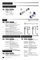
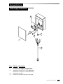
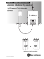
Installation, Operation and Service Manual
Lifeline Medical Systems
High Pressure Fully-Automatic
Manifold
HP
x
HP
High-Pressure x High-Pressure Models
Part No. 6-847700-00 Rev. G00 Pg. 1
Introduction
Table of Contents
INTRODUCTION
Abbreviations ..................................................2
Definition of Statements..................................3
Product Description ........................................3
INSTALLATION
Precautions.....................................................4
Manifold System Components........................4
Wall Mounting Instructions..............................5
Floor Mounting Instructions ..........................10
Main Outlet and Relief Valve Connection .....13
Power Supply Installation .............................14
Remote Alarm Connection ...........................15
Pigtail Installation / Cylinder Connection ......16
Initial Power-Up and Operational Testing .....19
Leak Testing..................................................22
OPERATION
Precautions...................................................23
Manifold Specifications .................................24
Manifold Components...................................25
Gas Flow Through The Manifold ..................30
Manifold Switch-Over....................................31
TESTING AND ADJUSTMENTS
Performance Verification ..............................32
Bank Regulator Pressure Adjustment ..........34
Line Regulator Pressure Adjustment............36
Pressure Switch Adjustment.........................37
SERVICE PROCEDURES
Precautions...................................................38
Routine Maintenance....................................38
Techniques For Leak-Tight Connections ......39
Pressure Switch Replacement .....................40
Bank Regulator Replacement.......................41
Line Regulator Replacement ........................42
Control Board Replacement .........................43
Wiring Diagram .............................................44
2
Part No. 6-847700-00 Rev. G00
ILLUSTRATED PARTS LISTS
Control Panel Components...........................45
Bank Regulator Components........................46
Line Regulator Components .........................47
Outlet / Dome Regulator Components..........48
Relief Vent Components ...............................49
Cabinet Cover Components .........................50
Cabinet Base Plate Components..................51
Header Components.....................................52
Pigtails ..........................................................54
Replacement Pigtail O-Rings / Washers ......54
Manifold Stand Kits .......................................54
Manifold Accessories....................................54
Power Supply Components ..........................55
WARRANTY .................................................56
Audience
This manual provides information related to the
installation and operation of the Lifeline High
Pressure manifold manufactured by
BeaconMedæs. Service information contained in
this manual is intended for use by technicians or
personnel qualified to repair and service medical
equipment.
Abbreviations
C
CGA
FNPT
MNPT
N/C
N/O
PSIG
SCFM
VAC
VDC
Common
Compressed Gas Association
Female National Pipe Thread
Male National Pipe Thread
Normally Closed
Normally Open
Pounds Per Square Inch- Gauge
Standard Cubic Feet Per Minute
Voltage, Alternating Current
Voltage, Direct Current
Introduction
Definition of Statements
Statements in this manual preceded by
following words are of special significance.
WARNING: Means there is a possibility
of injury or death to yourself or others.
CAUTION: Means there is a possibility of
damage to unit or other property.
NOTE: Indicates points of particular interest
for more efficient and convenient operation.
Product Description
Lifeline automatic changeover manifold is
designed to provide a reliable, uninterrupted
supply of gas to a hospital or other medical
facility. Manifold utilizes multiple high-pressure
cylinders divided into two equal banks. One
bank is designated as "Primary" source of gas
while other bank stands in reserve as
"Secondary" source.
wired to an external alarm or a building
management system.
When replacement cylinders are attached to
depleted bank, red lamp goes out and yellow
lamp illuminates indicating bank has been
automatically designated as secondary supply.
No other user interaction is required. Both sets
of dry contacts close to cancel any external
alarm condition.
An external power supply converts 120 VAC to
24 VAC to power manifold. Power supply is
connected to bottom of manifold control panel
via a 48" cable. Two sets of dry normally closed
alarm contacts can be accessed inside external
power supply, so under normal conditions, all
external wiring will be connected to power
supply, not manifold control panel.
Lifeline manifold is designed in accordance
with National Fire Protection Association (NFPA)
99.
Lights on front of manifold indicate status of
gas supply. Each bank has a green (IN USE),
yellow (READY), and red (EMPTY) lamp. When
primary bank of cylinders is depleted, manifold
will automatically switch to secondary bank of
cylinders without interruption of gas flow to
facility. Red lamp on depleted bank will
illuminate and two normally closed dry contacts
will open. One or both sets of contacts may be
Part No. 6-847700-00 Rev. G00
3
Installation
Precautions
Manifold System Components
WARNING:
• Tampering with gas specific connections shall
be prohibited. Do not alter, remove or modify
gas specific connections.
Manifold system may be shipped in more than
one carton, depending on number of cylinder
connections. Main carton contains following
items:
• Manifold control panel
• Wall mounting bracket (attached to manifold
control panel)
• Power supply assembly
• 3/4" source shut-off valve
• Installation, Operation, and Service Manual
• Keep all manifold parts, tools and work
surfaces free of oil, grease and dirt. These
and other flammable materials may ignite
when exposed to high pressure oxygen or
nitrous oxide.
• Do not use chemicals, lubricants or sealants
unless specified in these instructions.
• Before connecting cylinder to manifold,
momentarily open and close cylinder valve to
blow out dirt and debris.
• After connecting cylinder to manifold, open
cylinder valve s-l-o-w-l-y to allow heat of
compression to dissipate.
• Do not use flame or “sniff” tests for leaks.
• Do not apply heat to any part of the manifold
system.
• Always secure high-pressure cylinders with
racks, straps, or chains. Unrestrained
cylinders may fall over and damage or break
off cylinder valve.
• Do not repeatedly bend, sharply bend, or
twist copper pigtails as damage to tubing
may occur.
• Do not bend flexible pigtails into a radius
smaller than 3”.
• After manifold wall bracket has been
mounted, one person alone should not
attempt to lift and hang the manifold cabinet.
• Do not put manifold into operation until
verified by a qualified person per NFPA 99 or
other local standard.
4
Part No. 6-847700-00 Rev. G00
Additional cartons contain appropriate number of
header extensions and cylinder pigtail assemblies.
As a standard, header assemblies are configured
so cylinder inlets are on 5-inch centers. Cylinders
must be placed in a double row "staggered"
configuration. Cylinder inlets closest to manifold
control panel are intended for cylinders placed
directly beneath manifold control panel. Pigtails
for gases other than oxygen and helium are 24”
length stainless-steel flexible type. Oxygen and
helium pigtails are rigid copper and are pre-bent to
approximate shape for connection to cylinders.
Manifold is designed to be mounted directly to a
wall, but may be freestanding floor mounted with
addition of a manifold control panel floor mount kit
and an appropriate number of header floor mount
kits (ordered separately).
Installation
Wall Mounting Instructions
1. Remove manifold control panel from shipping
carton and place face down on foam packaging
insert.
2. Mounting bracket is shipped attached to back
of manifold control panel. Remove lower 3/8"
mounting nut as shown in Figure 1. Pull
bottom of bracket away from manifold control
panel and slide bracket off two upper control
panel mounting bolts.
3. Mark wall 79-3/4" from finished floor in location
where manifold will be mounted. Convert mark
to level horizontal line approximately 8" long.
NOTE:
A bracket mounting height of 79 3/4” allows for
adequate clearance beneath manifold when
utilizing standard “H” size cylinders (55” tall
overall). Bracket mounting height should be
increased proportionally if taller cylinders are to
be used.
Mounting
Bracket
3/8 Nut
Manifold
Control Panel
Figure 1
Part No. 6-847700-00 Rev. G00
5
Installation
Wall Mounting Instructions (cont.)
4. Place bracket flat against wall as shown in
Figure 2 and align top of bracket with level
horizontal line. Vertical center line of bracket
will be vertical center line of installed manifold.
Mounting top of bracket at 79-3/4" height will
net a 61" height from center of header to
finished floor.
5. Mark locations of mounting holes. Remove
bracket and drill mounting holes. Attach
bracket to wall with appropriate anchors (by
others). 3/8" diameter anchors are
recommended.
WARNING:
Do not attempt to lift manifold alone. Two people
are recommended in order to hang manifold onto
wall mounting bracket.
Figure 2
6
Part No. 6-847700-00 Rev. G00
Installation
Wall Mounting Instructions (cont.)
Figure 3
Part No. 6-847700-00 Rev. G00
7
Installation
Wall Mounting Instructions (cont.)
6. Hang manifold control panel on mounting
bracket. Top two control panel mounting bolts
will slide into slots of bracket. Bottom of
manifold control panel should be angled away
from bracket until top two bolts have been
inserted as shown in Figure 3. Bottom of
control panel can then be positioned toward
bracket so 3/8" mounting stud passes through
lower hole in mounting bracket. Install and
tighten 3/8" nut removed in step 2.
HEADER
ASSEMBLY
CAUTION:
Do not use thread sealant on header or pigtail
connections.
7. For manifolds with more than three cylinders
per bank, additional shipping cartons contain
extension headers and header wall brackets.
Depending on the number of cylinders, header
extensions are configured with two or three
cylinder inlets. Large manifold systems may
also include combinations and multiples of
each type of header extension. Remove large
union nut and plug from left and right manifold
inlets. Attach appropriate header extension to
manifold control panel. Position cylinder inlet
connections of each header extension so they
are pointing out (away from the wall) and
tighten header extension (Figure 4).
CAUTION:
Each header segment must be supported by a
header bracket before additional header
segments are added.
8
Part No. 6-847700-00 Rev. G00
Figure 4
Installation
Wall Mounting Instructions (cont.)
8. Each header extension is shipped with a
header bracket. Position bracket against wall
and on bottom side of header as shown in
Figure 6. Attach bracket to wall using
appropriate anchors (by others). 3/8" diameter
anchors are recommended.
9. Assemble u-bolt and bracket hardware as
shown. Tighten u-bolt nuts.
10 Additional header extensions may be attached
end to end if required.
11.Install large nut and plug removed in step 7 on
end of last header extension. Tighten large
nut.
HEADER
ASSEMBLY
U-BOLT
HEADER BRACKET
FLANGE NUTS
ANCHORS
(NOT PROVIDED)
3/8" DIA. ANCHORS
RECOMMENDED
Figure 6
Part No. 6-847700-00 Rev. G00
9
Installation
Floor Mounting Instructions
For floor mounting the manifold control panel
and headers, a manifold control panel stand kit
and an appropriate number of manifold header
stand kits should have been ordered separately.
One
manifold
control
panel stand
kit contains
all items
needed to
mount the
control
panel.
Depending
on the
number of
header
segments,
one or
more
header
stand kits
are
required.
A header
stand is required
for each header
segment.
Each header
stand kit contains
two vertical
stands and all
necessary items
to support one 2cylinder or 3cylinder header
segment on each
side of the
manifold.
10
Part No. 6-847700-00 Rev. G00
Verify contents of stand kits (Figures 7 and 8):
Figure 7
Figure 8
Installation
Floor Mounting Instructions (cont.)
1. Remove manifold control panel from shipping
carton and place face down on foam packaging
insert.
2. Mounting bracket is shipped attached to back
of manifold control panel. Remove lower 3/8"
mounting nut as shown in Figure 1. Pull
bottom of bracket away from manifold control
panel and slide bracket off two upper control
panel mounting bolts.
3. Only bracket will be needed at this time. Set
manifold control panel aside for installation
later.
NOTE:
Return control panel to shipping carton if
necessary to protect it and keep it clean.
4. Attach post base to one end of each 80-inch
channel as shown in Figure 9, Detail A. Use
two each 3/8" bolts, flat washers and channel
nuts per base. Tighten all four bolts.
5. Stand each channel / base side by side. Attach
manifold mounting bracket to both bases as
shown in Figure 9, Detail C. Use four each
3/8" bolts, flat washers and channel nuts per
base. Top of bracket should be level and
positioned 79 3/4" above floor. Tighten all four
bolts.
6. Position entire assembly in desired manifold
mounting location. Mark location of eight base
mounting holes. Move assembly aside and drill
holes. Minimum 3/8" diameter mounting bolts
are recommended (by others).
7 Reposition assembly over holes and install
mounting hardware (by others). Tighten all
mounting bolts.
8. Attach 12-inch channel to top of one vertical
channel as shown in Figure 9, Detail D. 12inch channel is used to mount power supply
and may be located on either side of manifold
control panel. Use flat plate, four each 3/8"
bolts, flat washers and channel nuts. Unlike
other hardware shown in Figure 9, 3/8 bolts will
pass through elongated holes in back of
channel and will be secured with channel nuts
inside. Tighten all four bolts.
9. Hang manifold control panel on mounting
bracket. Top two control panel mounting bolts
will slide into the slots of bracket. Bottom of
control panel should be angled away from
bracket until top two bolts have been inserted
as shown in Figure 3. Bottom of manifold
control panel can then be positioned toward
bracket so 3/8" mounting stud passes through
lower hole in mounting bracket. Install and
tighten 3/8" nut removed in step 2.
CAUTION:
Do not use thread sealant on header or pigtail
connections.
10.For manifolds with more than three cylinders
per bank, additional shipping cartons contain
extension headers and header wall brackets.
Depending on the number of cylinders, header
extensions are configured with two or three
cylinder inlets. Large manifold systems may
also include combinations and multiples of
each type of header extension. Remove large
union nut and plug from left and right manifold
inlets. Attach appropriate header extension to
manifold control panel. Position cylinder inlet
connections of each header extension so they
are pointing out (away from wall) and tighten
header extension (Figure 4).
Part No. 6-847700-00 Rev. G00
11
Installation
Floor Mounting Instructions (cont.)
CAUTION:
Each header segment must be supported by a
header bracket before additional header
segments are added.
11.Each header extension is shipped with a
header bracket. Each header bracket should
be attached to a manifold header stand.
Assemble each header stand by attaching a
post base to one end of 66-inch channel as
shown in Figure 9, Detail A.
Figure 9
12
Part No. 6-847700-00 Rev. G00
Installation
Floor Mounting Instructions (cont.)
Main Outlet and Relief Valve Connection
Use two each 3/8" bolts, flat washers and
channel nuts. Tighten all bolts.
12.Set header stand in a vertical position roughly
in alignment with two vertical control panel
stands. Position header bracket against
channel and on bottom side of header as
shown in Figure 6. Attach bracket to channel
as shown in Figure 9, Detail B. Use two each
3/8" bolts, flat washers and channel nuts.
Tighten all bolts.
13.Align header stand with two control panel
vertical stands, centering the header bracket
between two pigtail connections. Mark
locations of all four base mounting holes.
Move header stand aside and drill holes.
Minimum 3/8" diameter mounting bolts are
recommended (by others).
14.Reposition header stand over holes and install
mounting hardware (by others). Tighten all
mounting bolts.
15.Assemble u-bolt and bracket hardware as
shown in Figure 6. Tighten u-bolt nuts.
16.Additional header extensions may be attached
end to end if required.
17.Install large nut and plug removed in step 10
on end of last header extension. Tighten large
nut.
Manifold's main outlet and relief valve outlet
are supplied with zero clearance, o-ring sealed
unions. Main outlet connection is 3/4 FNPT and
relief valve is 1/2 FNPT. A 3/4" source shut-off
valve is also supplied with manifold control panel.
Inlet side of source shut-off valve is 3/4 MNPT for
connection directly to main outlet union. Outlet
side is a 3/4" nominal copper. A plugged, 1/8
FNPT port is provided on outlet side of valve and
may be removed to aid in purging.
CAUTION:
Close 3/4" source shut-off valve to prevent
debris from falling into manifold during brazing
procedure.
CAUTION:
To prevent damage to internal o-ring, do not
apply heat to relief valve union. Braze male
sweat adapter to relief piping prior to attaching to
union.
Part No. 6-847700-00 Rev. G00
13
Installation
Power Supply Installation
A separate power supply assembly is provided
with manifold control panel. Power supply
assembly should be mounted to wall on either
right or left side of manifold control panel with top
of power supply roughly in alignment with top of
manifold control panel. 1/4" diameter mounting
holes are provided in back of power supply box
(wall mounting hardware by others).
If floor mounting manifold control panel, mount
power supply assembly to 12-inch channel as
shown in Figure 9, Detail E. Use two each 1/4"
bolts and channel nuts per base. Tighten all bolts.
Power supply shall be connected to a building
installed circuit breaker. Circuit breaker shall be
marked as disconnecting means for manifold. It is
recommended that circuit breaker be in close
proximity to manifold power supply.
Power supply assembly houses a 24 VAC
transformer and terminal blocks for AC input
power and remote alarm connection. A 48” long
cable connects power supply to a six-pin
connector on bottom of manifold control panel.
NOTE:
All wiring shall be protected from physical
damage by raceways or conduit in accordance
with NFPA 70, National Electric Code.
Holes for 1/2” conduit are located on bottom of
power supply box for 120 VAC power and remote
alarm wiring.
120 VAC current draw will be less than 100
milliamperes. Primary of 24 VAC transformer
contains a 0.25 Amp time-delay fuse. Fuse type is
5 x 20 mm, GMD-250mA (240 VAC models use
0.125 Amp time -delay, type 5 x 20 mm, GMD125mA).
14
Part No. 6-847700-00 Rev. G00
Remote Alarm Connection
Two sets of dry, normally closed alarm contacts
are available inside power supply assembly for
connection to a remote alarm or building
automation system. Both sets of contacts are
independent of each other and will be closed
whenever manifold is powered and operating
normally (no alarm condition). Each set of
contacts will open if an alarm condition occurs
(manifold changeover), or if power is removed
from manifold. Alarm contacts are rated for 2 A @
30 VDC / 0.6 A @ 110 VDC / 0.6 A @ 125 VAC.
Refer to Figure 10 for power supply
connections.
Installation
Power Supply Wiring
Two Sets of
Dry Normally-Closed
Remote Alarm Contacts
120 VAC
Input
Power
1 2 3 4
Alarm 1
Ground
Alarm 2
Line
Neutral
Connects to bottom
of manifold control
panel
Bottom View
Three 1/2” conduit knockouts for AC power
input and alarm output field wiring.
Figure 10
Part No. 6-847700-00 Rev. G00
15
Installation
Pigtail Installation/Cylinder Connection
All manifolds other than oxygen and helium
utilize 24” length flexible stainless-steel braided
pigtails. All cylinders on the right bank of the
manifold, even those placed directly beneath
should be positioned so that the cylinder outlets
face right. All cylinders on the left bank of the
manifold, even those placed directly beneath
should be positioned so that the cylinder outlets
face left.
Figure 11 illustrates a typical 5 x 5 manifold
system utilizing 24” length flexible pigtails.
Oxygen and helium manifolds are supplied with
pre-formed rigid copper pigtails. All cylinders on
the right bank of the manifold, even those placed
directly beneath should be positioned so that the
cylinder outlets face right. All cylinders on the left
bank of the manifold, even those placed directly
beneath should be positioned so that the cylinder
outlets face left.
Figure 12 illustrates a typical 5 x 5 oxygen or
helium manifold utilizing pre-formed rigid copper
pigtails.
1. Remove plastic shipping caps from manifold
header pigtail connections.
2. Connect one end of pigtail assembly to header
connection. Coiled end of rigid copper pigtails
attaches to header connection.
3. Position gas cylinders as shown in Figures 11
and 12. Secure each cylinder to wall or floor
stand with chains or straps.
4. Connect pigtails to each cylinder. Rigid copper
pigtails used on oxygen and helium manifolds
are pre-formed to approximate required shape.
Lower end of rigid copper pigtails must be bent
90° toward cylinder outlets.
5. Tighten all pigtail connections firmly. Do not
over-tighten.
16
Part No. 6-847700-00 Rev. G00
WARNING:
All pigtail assemblies are shipped in sealed bags
and are cleaned as if for oxygen use. Manifold
header connections are clean and capped. Do
not unpackage or remove any cap until ready to
install. During installation use care to maintain
cleanliness.
WARNING:
• Do not repeatedly bend, sharply bend, or
twist copper pigtails as damage to tubing may
occur.
• Do not bend flexible pigtails into a radius
smaller than 3".
• Always secure cylinders with racks, straps, or
chains. Unrestrained cylinders may fall over
and damage or break off cylinder valve.
CAUTION:
Do not use thread sealant on header or pigtail
connections.
CAUTION:
Prior to connecting pigtail to cylinder, slightly
open and close each cylinder valve to blow out
dirt and debris.
NOTE:
Both ends of flexible pigtails are the same.
Either end may be connected to manifold
header. Rigid copper pigtails on oxygen and
helium manifolds are pre-formed and must be
connected as shown in Figure 12.
Installation
Pigtail Installation/Cylinder Connection (Cont.)
24” Pigtails
24” Pigtails
Figure 11
Part No. 6-847700-00 Rev. G00
17
Installation
Pigtail Installation/Cylinder Connection (Cont.)
Coiled ends of rigid copper pigtails
attach to header connections.
Lower ends of rigid copper
pigtails must be bent 90°
toward cylinder outlets.
Figure 12
18
Part No. 6-847700-00 Rev. G00
Installation
Initial Power-Up and Operational Testing
1. Release two latches on sides of manifold
control panel cover (one on each side).
Remove cover as shown in Figure 13.
2. Verify the following: (Refer to Figure 14 for
component location).
• Both master valves are turned fully
counterclockwise (open)
• All four line regulator isolation valves are open
(handles horizontal).
• Power supply cable has been attached to the
connector on bottom of manifold.
• Both red "Empty" indicators on front of manifold
are illuminated.
• If connected to a master alarm panel,
"Secondary Supply" alarm is activated.
3. Close 3/4" source shut-off valve.
Figure 13
Part No. 6-847700-00 Rev. G00
19
Installation
Initial Power-Up and Operational Testing (Cont.)
4. Slowly open one cylinder on right side of
manifold.
5. Verify the following:
• Right bank red "Empty" light goes out.
• Right bank green "In Use" light illuminates.
• Right bank cylinder contents gauge reads
cylinder pressure.
6. Slowly open one cylinder on left side of
7.
•
•
•
•
manifold.
Verify the following:
Left bank red "Empty" light goes out.
Left bank yellow "Ready" light illuminates.
Left bank cylinder contents gauge reads
cylinder pressure.
If connected to a master alarm panel,
3/4” Source
Shut-Off Valve
Vent Valve
Line Regulator
Isolation Valves
Master Valve
Line Regulator
Isolation Valves
Power Supply
Connector
Figure 14
20
Part No. 6-847700-00 Rev. G00
Master Valve
Installation
Initial Power-Up and Operational Testing (Cont.)
"Secondary Supply" alarm is not activated.
8. Close right bank cylinder. Slightly open vent
valve (Figure 14). Verify the following:
• Right bank cylinder contents gauge drops
slowly.
• As right cylinder contents gauge is nearly
depleted, manifold changes over to left bank.
• After change-over, right bank green "In Use"
light goes out and red "Empty" light illuminates.
• After change-over, left bank yellow "Ready"
light goes out and the green "In Use" light
illuminates.
9. Close vent valve.
10.Verify "Line Pressure" gauge reading is
acceptable.
11.Slowly open one cylinder on right side of
manifold.
12.Verify the following:
• Right bank red "Empty" light goes out.
• Right bank yellow "Ready" light illuminates.
• Right bank cylinder contents gauge reads
cylinder pressure.
13.Close left bank cylinder. Slightly open vent
valve. Verify the following:
• Left bank cylinder contents gauge drops slowly.
• As left cylinder contents gauge is nearly
depleted, manifold changes over to right bank.
• After change-over, left bank green "In Use"
light goes out and red "Empty" light illuminates.
• After change-over, right bank yellow "Ready"
light goes out and green "In Use" light
illuminates.
14.Close vent valve.
15.Slowly open one cylinder on left side of
manifold.
16.Verify the following:
• Left bank red "Empty" light goes out.
• Left bank yellow "Ready" light illuminates.
• Left bank cylinder contents gauge reads
cylinder pressure.
17 Close left and right side cylinders.
18.Record pressure readings of left and right bank
cylinder contents gauges.
19.Wait 15 minutes.
20.Compare current readings of left and right bank
cylinder contents gauges to those recorded in
step 18. If there is a noticeable pressure
change on either gauge, perform leak testing
described in the next section.
21.Reinstall manifold control panel cover.
22.Slowly open all cylinders on both banks of
manifold.
23.Open 3/4" source shut-off valve.
Part No. 6-847700-00 Rev. G00
21
Installation
Leak Testing
The following leak testing is recommended if a
leak is observed during the previous Initial PowerUp and Operational Testing procedure. If a
noticeable drop in either pressure gauge reading
was not detected, this leak testing is not required.
1. Release two latches on sides of manifold
control panel cover (one on each side).
Remove cover as shown in Figure 13.
2. Close 3/4" source shut-off valve.
3. Verify isolation valves on outlets of line
regulators are open.
4. Slowly open one cylinder on left and right bank
of manifold.
5. Close two internal isolation valves on inlets of
line regulators. (Refer to Figure 12 for
component location).
6. Close left and right side cylinders.
7. Record pressure readings of left and right bank
cylinder contents gauges and line pressure
gauge.
8. Wait 15 minutes.
9. Compare current readings of all three gauges
to those recorded in step 6.
10.A loss of pressure on line pressure gauge
indicates a leak downstream of line regulator
inlet isolation valves. A loss of pressure on left
or right cylinder contents gauges indicate a
leak in components upstream of line regulator
inlet isolation valves.
11.Locate leak by applying a small amount of an
oxygen compatible leak detector solution while
manifold is under pressure. Formation of
bubbles indicates a leak. Since manifold is
factory leak tested, suspect those items first
that were added during installation process.
For example, main outlet union fitting for leaks
downstream of line regulator isolation valves
and header connection points for leaks
upstream of line regulator isolation valves.
22
Part No. 6-847700-00 Rev. G00
12.Eliminate leaks by tightening or replacing
connections or tubing. Retest and verify all
leaks have been eliminated.
13.Open line regulator isolation valves.
14.Reinstall manifold control panel cover.
15.Slowly open all cylinders on both banks of
manifold.
16.Open 3/4" source shut-off valve.
CAUTION:
Avoid getting leak detector solution onto
electrical components. Wipe off excess leak
detector solution after testing.
Operation
Precautions
•
•
•
•
•
•
•
Manifold Specifications
WARNING:
Tampering with gas-specific connections shall
be prohibited. Do not alter, remove or modify
gas-specific connections.
Before connecting cylinder to manifold,
momentarily open and close cylinder valve to
blow out dirt and debris.
After connecting cylinder to manifold, open
cylinder valve s-l-o-w-l-y to allow heat of
compression to dissipate.
Always secure cylinders with racks, straps, or
chains. Unrestrained cylinders may fall over
and damage or break off cylinder valve.
Do not repeatedly bend, sharply bend, or
twist copper pigtails as damage to tubing may
occur.
Do not bend flexible pigtails into a radius
smaller than 3”.
Service to be performed by qualified medical
equipment technician.
NOTE:
In order to ensure proper manifold switchover
operation, do not set delivery (line) pressure less
than 40 PSI.
Parameter
Intermediate Pressure - Ready Bank
Dome Bias Pressure
Intermediate Pressure - In Use Bank
Intermediate Relief Valve
Line Regulator Relief Valve
Pressure Switch Setting (on pressure drop)
Maximum Inlet Pressure
All Lifeline Manifold systems are designed in
accordance with the current revision of NFPA 99.
There are three categories of Lifeline manifolds
depending upon the delivery pressure.
The following gas types are available for each
delivery pressure:
55 PSI Delivery Pressure
• Oxygen
• Nitrous Oxide
• Medical Air
• Carbon Dioxide
• Helium
• Carbon Dioxide/Oxygen, CO2 over 7%
• Oxygen/Carbon Dioxide, CO2 not over 7%
• Helium/Oxygen, Helium over 80%
• Oxygen/Helium, Helium not over 80%
• Argon
100 PSI Delivery Pressure
• Oxygen
• Medical Air
• Carbon Dioxide
180 PSI Delivery Pressure
• Nitrogen
• Instrument Air
Refer to Table 1 for the manifold's specifications.
Delivery (Line) Pressure - (see NOTE above)
55 PSI
100 PSI
180 PSI
70 PSI
210 PSI
210 PSI
55 PSI **
40 PSI
40 PSI
125 ± 10 PSI *
250 ± 10 PSI
250 ± 10 PSI
350 PSI
350 PSI
350 PSI
75 PSI
150 PSI
250 PSI
150 ± 5 PSI
300 ± 10 PSI
300 ± 10 PSI
3000 PSI
3000 PSI
3000 PSI
* The intermediate pressure value of the "In Use" bank is dependent upon the dome bias pressure. Variations from the 55 PSI
delivery pressure will affect the intermediate pressure reading.
** Same as delivery pressure.
Table 1
Part No. 6-847700-00 Rev. G00
23
Operation
Manifold Specifications (Cont.)
Flow Characteristics at 150 psig Inlet with 55 psig Delivery
60
Delivery Pressure (psig)
50
40
30
20
10
0
0
6
9
11
13
15
18
20
23
26
29
32
37
41
44
48
52
55
59
67
74
76
Delivery Flow (scfm)
Flow Characteristics at 300 psig Inlet with 100 psig Delivery
110
100
90
Delivery Pressure (psig)
80
70
60
50
40
30
20
10
0
0
8
10
12
14
16
18
20
24
28
32
Delivery Flow (scfm)
24
Part No. 6-847700-00 Rev. G00
37
43
50
Operation
Manifold Specifications (Cont.)
Flow Characteristics at 300 psig Inlet with 180 psig Delivery
200
180
160
Delivery Pressure (psig)
140
120
100
80
60
40
20
0
0
16
24
34
44
53
63
76
90
102
110
Delivery Flow (scfm)
Part No. 6-847700-00 Rev. G00
25
Operation
Manifold Components
Refer to Figures 15, 16 and 17.
Master Valve Multi-turn high pressure valves
allow flow from cylinders to be shut off. Master
valves use metallic seating surfaces. Both master
valves should always be turned to fully open,
maximum counterclockwise position.
Bank Regulator A dome loaded, single stage,
diaphragm type regulator. Used to reduce
incoming cylinder contents pressure to a lower
intermediate pressure. Bank regulator (one for
each bank of cylinders) has an internal adjusting
spring used to set a "base" pressure of
approximately 70 PSI (210 PSI on nitrogen
manifolds). “Dome" (i.e. bonnet or bell) of
regulator is a pressure tight chamber. When
pressure is applied to dome, amount of force
applied is added to force of adjusting spring. For
example, when 55 PSI of pressure is applied to
dome, 70 PSI base pressure setting is raised to
approximately 125 PSI.
Pressure Switch An adjustable, single pole,
normally open pressure switch. A pressure switch
is connected to high pressure port of each bank
regulator in order to monitor pressure in each
bank of cylinders. When adequate cylinder
pressure is applied, switch contacts are held
closed. When cylinder pressure drops to switch
setting of 150 PSI (300 PSI for nitrogen
manifolds), switch contacts will open.
Check Valve Soft-seal check valves are provided
downstream of each bank regulator to allow
service of upstream components while the other
side of the manifold is in use.
26
Part No. 6-847700-00 Rev. G00
Intermediate Relief Valve The intermediate relief
valve protects the components between the bank
regulators and the line regulators in the event of
an overpressure condition caused by bank
regulator failure. The outlet of the relief valve is
piped to a common relief valve port on top of the
manifold.
Line Regulator Isolation Valve Quarter-turn ball
valves are provided upstream and downstream of
each line regulator. These valves allow for
removal and servicing of one line regulator while
other is in use. All four isolation valves are
normally in open position.
Line Regulator A single stage, diaphragm type
regulator used to reduce manifold's intermediate
pressure to normal hospital line pressure. Two
line regulators are provided per NFPA 99
requirements to allow for isolation and service of
one while other is in use.
Line Relief Valve A relief valve to prevent overpressurization of the hospital piping system by
failure of a line regulator. Outlet of relief valve is
piped to a common relief valve port on top of
manifold.
Dome Regulator A single stage, diaphragm type,
relieving regulator used to limit amount of
pressure provided to domes of bank regulator.
Used only on nitrogen manifolds and manifolds
with 100 PSI delivery pressures.
Solenoid Valve A 24 VDC, solenoid assembly
used to direct dome bias pressure to one of the
bank regulators. As dome bias pressure is
directed to one of bank regulator, dome of other
bank regulator is vented through solenoid valve.
Operation
Manifold Components (Cont.)
Front Panel Indicators Six front panel indicators
monitor the status of the manifold. The indicators
are 24 VDC LED (Light Emitting Diode) type.
Control Board An electronic circuit board that
controls manifold switchover. The control board
monitors the pressure switches and controls the
solenoid valve in order to initiate manifold
switchover. The control board illuminates the
appropriate front panel indicators and also
provides dry contacts for activation of the external
master alarms. Power to the control board is
provided by the external power supply.
Power Supply (Not Shown) An external NEMA 3R
rated enclosure contains a 120 VAC to 24 VAC
transformer. The 24 VAC is routed to the manifold
control board via a detachable six-conductor cable
and connector. An in-line 0.25 amp slow-blow
fuse is provided in 120 VAC power line. Terminal
blocks inside power supply allow for connection of
AC input power and master alarm panel normally
closed dry contact outputs. Refer to Figure 10 for
power supply wiring.
NOTE:
Some components not shown for clarity.
Control Board
Solenoid Valve
Front Panel
Indicators
Left Bank Pressure Gauge
Line Pressure Gauge
Right Bank Pressure Gauge
Figure 15
Part No. 6-847700-00 Rev. G00
27
Operation
Manifold Components (Cont.)
NOTE:
Some components not shown for clarity.
1/8-27 NPT Port
3/4” Source Shut-off
Valve
Service Valve
Relief Vent Outlet
Dome Regulator
Line Relief Valve
Vent Valve
Line Regulator
Isolation Valve
Line Regulator
Isolation Valve
Line Regulator
Line Regulator
Line Regulator
Isolation Valve
Line Regulator
Isolation Valve
Check Valve
Check Valve
Intermediate Relief
Valve
Left
Bank Regulator
Right
Bank Regulator
Pressure Switch
Pressure Switch
Master Valve
Master Valve
Figure 16
28
Part No. 6-847700-00 Rev. G00
Operation
Manifold Components (Cont.)
Figure 17
Part No. 6-847700-00 Rev. G00
29
Operation
Gas Flow Through the Manifold
Refer to Figure 17.
High pressure gas is provided to left and right
manifold bank inlets via cylinders, pigtails, and
header assemblies. Flow of high pressure gas
through left and right side of manifold is exactly
the same, each passing through a master valve
and then directly to a bank regulator. Cylinder
pressure is also applied to a normally open
pressure switch (closes when pressure is applied)
and a front panel high pressure gauge.
Bank regulators reduce incoming cylinder
pressures to an intermediate pressure. Bank
regulators are referred to as a "dome loaded" type
of regulator. These regulators have an internal
adjusting spring manually set at a specific
pressure similar to other diaphragm type pressure
regulators. In addition to internal adjusting spring,
bias pressure may be applied to dome of regulator
(adjusting spring side of diaphragm) thus boosting
pressure above what is manually set by adjusting
spring. This output pressure boost will be
approximately equal to amount of bias pressure.
For example, if a bank regulator is manually
adjusted to 70 PSI via internal adjusting spring,
and a dome bias pressure of 55 PSI is applied,
output pressure will increase to approximately 125
PSI (70 + 55). When bias pressure is removed,
output pressure setting will return to 70 PSI.
Outputs of both left and right bank regulators
pass through check valves and connect together
upstream of a dual line regulator assembly. An
intermediate relief valve protects components
between bank and line regulators in the event of a
bank regulator seat failure.
Dual line regulator assembly consists of two
30
Part No. 6-847700-00 Rev. G00
line regulators plumbed in parallel with upstream
and downstream isolation 1/4 turn ball valves.
Output of both line regulators tee together and exit
at manifold's main outlet. A line relief valve and
line pressure gauge are connected to manifold's
main outlet.
Outlet pressure is routed to a dome regulator
reducing pressure to 40 PSI at solenoid valve.
Solenoid valve switches 40 PSI (dome bias
pressure) to one of the bank regulators. When
one bank regulator is supplied bias pressure, the
other bank regulator's dome is vented to
atmosphere. An electronic circuit board controls
solenoid valve based upon input from right and left
pressure switches. Solenoid valve directs bias
pressure to bank designated as primary.
Manifolds designed for 55 PSI nominal output
pressure do not incorporate a dome regulator.
Full line pressure (55 PSI) is routed directly to
solenoid valve and is used as dome bias.
Operation
Manifold Switch-Over
After electrical power has been applied to
manifold, side pressurized first is designated
primary or "In Use" bank. In order to simplify the
following explanation, we will arbitrarily select right
side of manifold as primary bank. Green "In Use"
light on right side is illuminated. Yellow "Ready"
light is illuminated on left (secondary) bank.
Solenoid valve directs dome bias pressure to
bank regulator on right side. If we use a 55 PSI
oxygen manifold as an example, output of right
bank pressure regulator is approximately 125 PSI
(70 PSI base pressure + 55 PSI bias pressure).
Output of left bank regulator is 70 PSI (base
pressure only, no bias pressure). Since bank
regulator on right side has highest pressure, all
flow is supplied by right bank of cylinders.
approximately 125 PSI. Right bank regulator has
no dome bias pressure and its output pressure is
controlled only by base pressure (70 PSI). All flow
is supplied by left bank of cylinders until pressure
in left bank drops to left pressure switch setting
(150 PSI). Left pressure switch then opens,
causing switchover to right side in same fashion
as previously described.
In the event of a power failure, unpowered
solenoid valve will direct dome bias pressure to
left bank regulator. A switchover alarm will be
activated on master alarm panels. All flow will be
supplied by left bank of cylinders until depleted.
Right bank of cylinders will then automatically
begin to supply flow.
As cylinder pressure on right side depletes,
pressure falls to pressure switch setting (150 PSI).
Right side pressure switch opens signaling circuit
board to switch solenoid valve. Solenoid valve
vents dome bias pressure from right bank
regulator and directs bias pressure to left bank
regulator. Green light on right side goes out and
red "Empty" light illuminates. Yellow light on left
side goes out and green "In Use" light illuminates.
Circuit board alarm contacts open in order to
activate master alarm panel switchover alarm. All
flow is supplied by left bank of cylinders.
When cylinders on right side are replaced and
pressure is restored, right pressure switch closes
and signals circuit board. Circuit board will in turn,
cancel remote switchover alarm, turn off right side
red light and illuminate right side yellow "Ready"
light.
Since left bank regulator has dome bias
pressure applied, its output pressure is boosted to
Part No. 6-847700-00 Rev. G00
31
Testing and Adjustments
Performance Verification
Use following test steps to verify manifold’s
functional performance.
1. Remove manifold cover.
2. Before beginning test, verify following:
• Both left and right side master valves are
turned to full counterclockwise open position.
• Cylinders are attached to both sides of
manifold and left and right bank pressure
gauges indicate at least 1800 PSI (at least 600
PSI for Nitrous Oxide or Carbon Dioxide).
• Power is applied to manifold.
WARNING:
If necessary, most service, adjustment, and
testing can be performed while manifold is in
service. However, this should only be done by
qualified technicians experienced in servicing
medical equipment. Servicing and testing
manifold while not in use, with 3/4" source shutoff valve closed, is preferred. Following test
procedure assumes manifold is not in service.
3. If manifold is not in use, close 3/4" source shutoff valve.
4. Verify two right-side line regulator isolation
valves are open and two left-side line regulator
isolation valves are closed.
5. As a starting point for this procedure, set
manifold so right bank is in use. If right bank
green light is illuminated, proceed to next step.
If left bank green light is illuminated, manually
switch manifold to right side by pressing left
switch on control board.
6. Verify only right bank green "IN USE" and left
bank yellow "READY" lights are illuminated.
7. If manifold is connected to a master alarm
panel, verify manifold switchover alarm is not
activated.
32
Part No. 6-847700-00 Rev. G00
8. If manifold is equipped with a dome regulator,
verify dome regulator’s gauge reads 40-45 PSI.
If manifold does not have a dome regulator,
proceed to next step.
NOTE:
The dome regulator’s red locking ring must be
pulled out away from the regulator body before
adjustment knob can be turned. After
adjustment, push locking ring inward to lock
knob. Since dome regulator is self-relieving, it is
recommended that dome regulator always be
increased to the desired pressure. For example,
if dome regulator pressure is too high, first lower
pressure to approximately 30 PSI. Then raise
pressure to between 40-45 PSI.
9. Slightly open vent valve to create a small flow
of gas through manifold.
10.Verify pressure gauge reading (intermediate
pressure - in use bank) on right-side bank
regulator is as indicated in Table 1. If pressure
is not correct, refer to Bank Regulator Pressure
Adjustment procedure.
11.Verify front panel line pressure gauge reading
is as indicated in Table 1 (delivery pressure). If
pressure is not correct, refer to Line Regulator
Pressure Adjustment procedure. Note reading
for later use.
NOTE:
Line pressure values listed in Table 1 are
nominal factory settings. Actual customer
settings may vary.
12.Close vent valve. Watch pressure gauge
readings of right side bank regulator and front
panel line pressure gauge for at least five
minutes. Readings may be slightly higher
without vent flow. Verify readings do not
continue to increase.
Testing and Adjustments
Performance Verification (Continued)
13.Close all cylinders on right side of manifold.
Open vent valve slightly so front panel right
bank high pressure gauge drops slowly. Verify
manifold switches to left bank when right bank
high pressure gauge drops to value indicated in
Table 1. If pressure value is not correct, right
pressure switch needs adjustment. Refer to
Pressure Switch Adjustment procedure.
14.Close vent valve. Verify only left bank green
"IN USE" and right bank red "EMPTY" lights
illuminate.
15.If manifold is connected to a master alarm
panel, verify manifold switchover alarm is
activated.
16.Slowly open one cylinder on right side. Verify
right bank red light goes out and right bank
yellow "READY" light illuminates.
17.Close two right-side line regulator isolation
valves and open two left-side line regulator
isolation valves.
18.Slightly open vent valve to create a small flow
of gas through manifold.
19.Verify pressure gauge reading (intermediate
pressure - in use bank) on left-side bank
regulator is as indicated in Table 1. If pressure
is not correct, refer to Bank Regulator Pressure
Adjustment procedure.
20.Verify front panel line pressure gauge reading
is same as in step 11. If pressure is not
correct, refer to Line Regulator Pressure
Adjustment procedure.
21.Close vent valve. Watch pressure gauge
readings of left side bank regulator and front
panel line pressure gauge for at least five
minutes. Readings may be slightly higher
without vent flow. Verify readings do not
continue to increase.
22.Close all cylinders on left side of manifold.
Open vent valve slightly so front panel left bank
high pressure gauge drops slowly. Verify
manifold switches to right bank when left bank
high pressure gauge drops to value indicated in
Table 1. If pressure value is not correct, left
pressure switch needs adjustment. Refer to
Pressure Switch Adjustment procedure.
23.Close vent valve. Verify only right bank green
"IN USE" and left bank red "EMPTY" lights
illuminate.
24.Slowly open one cylinder on left side. Verify
left bank red light goes out and left bank yellow
"READY" light illuminates.
25.Open two right side line regulator isolation
valves.
26.Close left and right side cylinders.
27 Record pressure readings of left and right bank
cylinder contents gauges.
28.Verify after 15 minutes, pressure gauge
readings have not changed.
29.Slowly open all cylinders on both banks of
manifold.
30.Using circuit board switches, switch manifold to
bank of cylinders with least pressure.
31.Reinstall manifold control panel cover.
32.Open 3/4" source shut-off valve.
Part No. 6-847700-00 Rev. G00
33
Testing and Adjustments
Bank Regulator Pressure Adjustment
Following procedure describes process of
setting bank regulator's "base" pressure. This
procedure should only need to be performed if
bank regulator pressures were not within
acceptable limits during performance verification
procedure or after installation of a new bank
pressure regulator.
Base pressure setting is a mechanical
adjustment controlled by regulator's internal
adjusting spring and is regulator's output pressure
without any dome bias. Recommended settings
are listed in Table 1 under heading of
"Intermediate Pressure - Ready Bank". After base
pressure has been set, pressure will be increased
by amount of dome bias pressure applied. Refer
to Figure 16 for location of components called out
in this procedure.
1. Remove two front panel screws A (Figure 18).
Loosen two hinge screws B (Figure 18). Fold
front panel down to service position as shown
in Figure 19. Lightly tighten two hinge screws.
2. Close service valve.
3. Using control board switches, cycle manifold
from bank to bank to vent residual dome bias
pressure.
NOTE:
Some early production manifolds that
incorporate a dome regulator do not have a
dome bias shut-off valve. To shut-off dome bias
pressure on these units, set dome regulator to its
minimum setting.
NOTE:
By closing service valve (if equipped), manifold's
outlet pressure gauge is also isolated. Cycling
manifold to vent residual dome bias pressure will
also vent pressure shown on manifold's outlet
pressure gauge. Actual outlet pressure supplied
by manifold is not affected by following
procedure.
34
Part No. 6-847700-00 Rev. G00
4. Using 1/4" Allen wrench, remove pipe plug
from dome of bank regulator(s) to be adjusted.
5. Shut off all cylinders on both banks of manifold.
6. Open vent valve to vent all pressure from
manifold.
7. Close vent valve and slowly open one cylinder
on side of manifold that needs adjustment. For
example, if right bank regulator needs
adjustment, open one cylinder on right side of
manifold.
8. Slightly open vent valve to create a small flow
of gas through manifold.
9. Using 1/4" Allen wrench, set bank regulator to
the value specified in Table 1 (Intermediate
Pressure - Ready Bank).
10.Close vent valve and cylinder.
11.If other bank regulator also needs to be
adjusted, repeat steps 6 through 10.
12.Apply Teflon tape and reinstall pipe plug in
dome of bank regulator(s).
13.Loosen front panel hinge screws and return
front panel to its upright position. Reinstall two
front panel screws and tighten hinge screws.
14.Slowly open all cylinders on both manifold
banks.
15.Open service valve or reset dome regulator to
40-45 PSI.
NOTE:
Dome regulator’s red locking ring must be pulled
out away from regulator body before adjustment
knob can be turned. After adjustment, push
locking ring inward to lock knob. Since dome
regulator is self-relieving, it is recommended
dome regulator always be increased to desired
pressure. For example, if dome regulator
pressure is too high, first lower pressure to
approximately 30 PSI. Then raise pressure to
between 40-45 PSI.
Testing and Adjustments
A
B
Figure 18
NOTE:
Some components not shown for clarity.
Switches
Figure 19
Part No. 6-847700-00 Rev. G00
35
Testing and Adjustments
Line Regulator Pressure Adjustment
Following procedure describes process of
setting line regulator pressure. This procedure
should only need to be performed if line regulator
pressures were not within acceptable limits during
Performance Verification procedure or after
installation of a new line pressure regulator.
When shipped from factory, inlet and outlet
isolation valves to both line regulators are in open
position. Refer to Figure 16 for location of
components called out in this procedure.
NOTE:
If inlet and outlet isolation valves for both line
regulators are open, manifold's outlet pressure
gauge will indicate pressure of line regulator with
highest setting. Verify setting of each regulator
individually as described in following procedure.
1. Open two right-side line regulator isolation
valves and close two left-side line regulator
isolation valves.
2. Slightly open vent valve to create a small flow
of gas through manifold.
3. Using 6mm Allen wrench, turn right line
regulator adjusting screw for an appropriate
front panel output pressure gauge reading.
Note reading for later use. Refer to Table 1
(delivery pressure) for factory settings.
4. Open two left-side line regulator isolation
valves and close two right-side line regulator
isolation valves.
5. Using 6mm Allen wrench, turn left line regulator
adjusting screw for same outlet pressure gauge
reading noted in step 3.
6. Close vent valve.
7. Open two right-side line regulator isolation
valves.
36
Part No. 6-847700-00 Rev. G00
Testing and Adjustments
Pressure Switch Adjustment
Following procedure describes process of
setting pressure switches. This procedure should
only need to be performed if manifold switchover
pressures were not within acceptable limits during
Performance Verification procedure.
Recommended settings are listed in Table 1.
Pressure switch is a normally open type that
closes when pressure in excess of switch setting
is applied. When cylinder pressure is applied to
both banks of manifold, both pressure switches
are closed. When cylinder pressure of "IN USE"
bank drops to switch setting, manifold will switch
to opposite cylinder bank. Switches should
always be adjusted as pressure decreases. If
pressure switch can not be set, switch must be
replaced. Pressure switches are not repairable.
Refer to Figure 16 for location of components
called out in this procedure.
1. Verify at least one cylinder is open on each
bank of manifold.
2. Using circuit board switches, switch manifold to
bank whose pressure switch is to be adjusted.
For example, if pressure switch on right side is
to be adjusted, press left circuit board switch so
green "IN USE" light on right bank is
illuminated.
3. Close cylinders on "IN USE" bank.
4. Slightly open vent valve to create a small flow
of gas through manifold. Front panel cylinder
contents gauge for "IN USE" bank should begin
to drop. Adjust vent valve so gauge drops very
slowly.
5. Note gauge reading when manifold switchover
takes place. Recommended settings are listed
in Table 1.
6. Close vent valve.
7. If switch adjustment is necessary, slide collar of
switch toward wires to access internal
adjustment barrel. Insert tip of small
screwdriver into adjustment barrel and rotate
barrel (Figure 20).
NOTE:
When viewing switch from wire end, rotating
barrel clockwise will raise switch setting.
Counterclockwise rotation will lower switch
setting. Make small adjustments and retest as
follows:
8. Slowly open one cylinder on bank of manifold
just tested.
9. Using circuit board switches, switch manifold
back to bank just tested.
10.Repeat steps 3 through 9 until pressure
switch(es) have been set within acceptable
limits.
11.Slide pressure switch collar back to original
position.
Adjustment
Barrel
Collar
Figure 20
Part No. 6-847700-00 Rev. G00
37
Service Procedures
Precautions
•
•
•
•
•
•
•
•
•
•
•
38
WARNING:
Tampering with gas-specific connections shall
be prohibited. Do not alter, remove or modify
gas-specific connections.
Keep all manifold parts, tools, and work
surfaces free of oil, grease, and dirt. These
and other flammable materials may ignite
when exposed to high pressure oxygen or
nitrous oxide.
Use only proper repair tools and parts. Use
only approved repair parts provided by
BeaconMedæs.
Do not use chemicals, lubricants or sealants
unless specified in these instructions.
Before connecting cylinder to manifold,
momentarily open and close cylinder valve to
blow out dirt and debris.
After connecting cylinder to manifold, open
cylinder s-l-o-w-l-y to allow heat of
compression to dissipate.
Do not use flame or "sniff" test for leaks.
Do not apply heat to any part of manifold
system.
Always secure cylinders with racks, straps, or
chains. Unrestrained cylinders may fall over
and damage or break off cylinder valve.
Do not repeatedly bend, sharply bend, or
twist copper pigtails as damage to tubing may
occur.
Do not bend flexible pigtails into a radius
smaller than 3".
Part No. 6-847700-00 Rev. G00
Routine Maintenance
Daily:
• Visually inspect manifold for normal operation.
Record front panel indicator status (e.g. left
bank "IN USE", right bank "READY").
• Record left and right bank pressure gauge
readings.
• Record line pressure gauge reading.
At Cylinder Replacement:
• Visually inspect each pigtail for cleanliness,
and damage. Do not use and immediately
replace dirty or damaged pigtails.
• Check for leaks at cylinder to pigtail connection
using oxygen compatible leak detector solution.
Annually:
• Verify manifold operation using Performance
Verification procedure.
Every 3-5 Years:
• Replace pigtails.
Service Procedures
Techniques For Leak-Tight Connections
Lifeline manifold utilizes four different types of
connection between internal components.
• Threaded pipe fittings.
• Parker brand "A-Lok" fittings.
• Parker brand "Prestolock" fittings.
• O-ring face seal fittings.
Threaded pipe fittings should be sealed with
Teflon tape. Remove old Teflon tape from both
male and female threads. Use care so all
fragments are removed from threads and interior
of fittings. Apply Teflon tape to male pipe threads.
Approximately 2 to 3 turns should be sufficient.
Do not cover first thread with tape. Assemble
fittings and tighten.
Parker brand "A-Lok" fittings are a type of
compression fitting. Mark nut and fitting prior to
disassembly. Before retightening, make sure
assembly has been inserted into fitting until ferrule
seats in fitting. Retighten nut by hand. Torque nut
with wrench until marks line up, which indicates
that fitting has been tightened to its original
position. A noticeable increase in mechanical
resistance will be felt indicating ferrule is being
resprung into sealing position. Then, tighten nut
1/12 of a turn (1/2 of a wrench flat) past original
position. If tightening a fitting for first time, make
sure tube has been inserted completely into fitting
and tighten nut by hand. Wrench tighten nut an
additional 1-1/4 turns.
Parker brand "Prestolock" fittings are used
throughout manifold to attach each end of black
nylon tubes. To release tube from fitting, press
fitting's release button against body while pulling
tube out. If you experience difficulty, open a
Crescent wrench so that it just slides over outside
of nylon tube. Push side of Crescent wrench
against fitting's release button while pulling out on
tube. Verify end of tube is cut square and free of
burrs and debris. Insert tube into fitting until it
bottoms. Pull on tubing to verify it is properly
retained in fitting.
O-ring face seal fittings are used on main outlet
and relief valve vent outlet unions and four line
regulator isolation valve unions. Leaks at these
connections can be caused by damaged o-rings or
scratches / nicks in brass fittings where o-rings
contact. Replace either o-ring or fitting as
necessary to correct leak. Lubrication of o-ring is
not required.
Part No. 6-847700-00 Rev. G00
39
Service Procedures
Pressure Switch Replacement
Following procedure describes process of
replacing pressure switch. If necessary, pressure
switch replacement can be performed while
manifold is in service. However, this should only
be done by qualified technicians experienced in
servicing medical equipment.
1. Remove two front panel screws A (Figure 18).
Loosen two hinge screws B (Figure 18). Fold
front panel down to service position as shown
in Figure 19. Lightly tighten two hinge screws.
2. Disconnect power supply connector from
bottom of manifold cabinet.
3. Close all cylinders on side of manifold where
pressure switch will be replaced.
4. Vent pressure from bank that was shut off in
step 3 by slightly loosening compression nut on
back of front panel bank pressure gauge.
5. Using small blade screwdriver, remove violet
and blue pressure switch wires from control
board terminals. Note location of each wire.
6. Cut cable ties and remove pressure switch
wires from manifold's harness.
7. Verify all pressure has been vented. Remove
old pressure switch from bank regulator body.
CAUTION:
Bank regulator high pressure parts incorporate
filter material between inner and outer wire
screens. Take care not to dislodge filter or
screens when removing and reinstalling pressure
switch.
8. Apply Teflon tape to threads of new switch and
install into bank regulator body. Tighten switch
so switch adjustment opening is facing
outward.
9. Route switch wires and attach them to
appropriate control board terminals. Secure
wires with cable ties.
40
Part No. 6-847700-00 Rev. G00
10.Loosen front panel hinge screws and return
front panel to upright position. Reinstall two
front panel screws and tighten hinge screws.
11.Tighten compression nut on back of front panel
bank pressure gauge.
12.S-l-o-w-l-y open each cylinder on side of
manifold where pressure switch was replaced.
13.Reconnect power supply connector to bottom
of manifold cabinet.
14.Verify new switch is set correctly by performing
appropriate steps of Performance Verification
procedure.
Service Procedures
Bank Regulator Replacement
Following procedure describes process of
replacing bank regulator. If necessary, bank
regulator replacement can be performed while
manifold is in service. However, this should only
be done by qualified technicians experienced in
servicing medical equipment. Internal repair of
bank regulator is not recommended.
1. Remove two front panel screws A (Figure 18).
Loosen two hinge screws B (Figure 18). Fold
front panel down to service position as shown
in Figure 19. Lightly tighten two hinge screws.
2. Close all cylinders on side of manifold where
bank regulator will be replaced.
3. Vent pressure from bank that was shut off in
step 2 by slightly loosening the compression
nut on back of front panel bank pressure
gauge.
NOTE:
Replacement bank regulator is supplied with inlet
nut and tailpiece. All other fittings, pressure
gauge and pressure switch must be removed
from old regulator and reused.
CAUTION:
Bank regulator high pressure parts incorporate
filter material between inner and outer wire
screens. Take care not to dislodge filter or
screens when removing and reinstalling pressure
switch.
NOTE:
Pressure switch may be removed from bank
regulator body without disconnecting pressure
switch wires from control board. Carefully
unscrew pressure switch and allow wires to twist.
Removal of switch typically requires 4 - 5
revolutions. When reinstalling switch, twist wires
4 - 5 revolutions in a counterclockwise direction
so when tightened, wires will return to
approximate original position.
NOTE:
Refer to Techniques For Leak-Tight Fittings for
recommendations concerning removal and
reassembly of fittings.
4. Remove 5/8" OD copper tube from outlet of
bank regulator.
NOTE:
Check valves downstream of line regulators will
prevent back flow. Check valves are intended to
prevent gross leaks during service and may not
be bubble tight.
5. Remove pressure switch from bank regulator
body.
6. Remove 1/8" copper tube between bank
regulator elbow fitting and front panel bank
pressure gauge.
7. Loosen large union nut on inlet of bank
regulator.
8. Remove nylon tube from regulator dome.
9. Remove two bank regulator bracket mounting
nuts.
10.Remove regulator and bracket from manifold.
11.Remove pressure gauge and remaining fittings
from old regulator.
12.Noting regulator/bracket alignment, remove
regulator bracket from old regulator.
13.Install regulator bracket on new regulator.
Align bracket as noted above.
14.Using Teflon tape, reinstall pressure gauge and
fittings into new regulator body.
NOTE:
Some pressure ports in new regulator body will
be shipped with pipe plugs. Remove plugs
where applicable.
15.Attach new regulator and bracket to manifold's
base plate. Hand-tighten mounting nuts.
Part No. 6-847700-00 Rev. G00
41
Service Procedures
Bank Regulator Replacement (Cont.)
16.Tighten large nut on inlet of new bank
regulator.
17.Install 5/8" OD copper tube.
18.Tighten regulator bracket mounting nuts.
19.Install pressure switch. Remember to pre-twist
pressure switch wires.
20.Install 1/8" copper tube between regulator
fitting and front panel bank pressure gauge.
21.Reinstall nylon tube.
22.Slowly open cylinders and set bank regulator's
output pressure as described in Bank
Regulator Pressure Adjustment procedure.
Line Regulator Replacement
Following procedure describes process of
replacing line regulator. If necessary, line regulator
replacement can be performed while manifold is in
service. However, this should only be done by
qualified technicians experienced in servicing
medical equipment. Internal repair of line
regulator is not recommended.
NOTE:
Refer to Techniques For Leak-Tight Fittings for
recommendations concerning removal and
reassembly of fittings.
1. Close two isolation valves on inlet and outlet of
line regulator to be replaced.
2. Loosen union nuts on two closed isolation
valves.
3. Remove two line regulator bracket mounting
nuts.
4. Remove line regulator and bracket from
manifold.
5. Noting regulator/bracket alignment, remove
regulator bracket from old regulator.
6. Install regulator bracket on new regulator.
Align bracket as noted above.
NOTE:
Unused pressure ports in new line regulator
body will be shipped with pipe plugs.
7. Noting orientation of fittings, remove fittings
from old regulator.
8. Install fittings on new regulator. Verify correct
orientation of fittings.
9. Inspect o-ring removed from each isolation
valve union. If damaged, replace o-ring.
10.Insert o-ring into each isolation valve and
attach new regulator and bracket to manifold's
base plate. Hand-tighten mounting nuts.
11.Tighten two isolation valve union nuts.
12.Tighten line regulator bracket mounting nuts.
42
Part No. 6-847700-00 Rev. G00
Service Procedures
Line Regulator Replacement (Cont.)
13.Open line regulator isolation valves and set line
regulator's output pressure as described in
Line Regulator Pressure Adjustment
procedure.
Control Board Replacement
Following procedure describes process of
replacing manifold's electronic control circuit
board. If necessary, control board replacement
can be performed while manifold is in service.
However, this should only be done by qualified
technicians experienced in servicing medical
equipment. Repair of the control board is not
recommended.
1. Remove two front panel screws A (Figure 18).
Loosen two hinge screws B (Figure 18). Fold
front panel down to service position as shown
in Figure 19. Lightly tighten two hinge screws.
2. Disconnect power supply connector from
bottom of manifold cabinet.
3. Using small blade screwdriver, remove each
wire from control board terminals.
4. Remove four control board screws. Note
orientation of old control board and remove
from manifold.
5. Install new control board and secure with four
screws.
6. Connect each wire to appropriate terminal.
Refer to wiring diagram, Figure 21 for wire
locations.
7 Loosen front panel hinge screws and return
front panel to upright position. Reinstall two
front panel screws and tighten hinge screws.
8. Reconnect power supply connector to bottom
of manifold cabinet.
9. Verify correct operation of new control board by
performing Performance Verification.
Part No. 6-847700-00 Rev. G00
43
Service Procedures
Wiring Diagram
“EMPTY”
RED
“READY”
YELLOW
“IN USE”
GREEN
WHITE
WHITE
RED
RED
CONTROL BOARD
WHITE
RED
WHITE
RED
WHITE
WHITE
RED
RED
LEFT BANK
FRONT PANEL LIGHTS
PRESSURE SWITCH
VIOLET
VIOLET
BLUE
BLUE
BLACK
SWITCHES
YELLOW
“READY”
GREEN
“IN USE”
PRESSURE SWITCH
RIGHT “SECONDARY SUPPLY”
BLACK
BROWN (PIN 7
RED (PIN 3)
GREEN (PIN 2)
BLUE (PIN 1)
WHITE (PIN 6)
BLACK (PIN 5)
SOLENOID VALVE
POWER SUPPLY
BOTTOM CABINET
POWER SUPPLY
CONNECTOR
123456
BLACK (PIN 5)
WHITE (PIN 6)
(FIELD WIRING)
LINE
NEUTRAL
RED (PIN 3)
BROWN (PIN 7)
BLUE (PIN 1)
GREEN (PIN 2)
GROUND
Figure 26
Part No. 6-847700-00 Rev. G00
“EMPTY”
RIGHT BANK
FRONT PANEL LIGHTS
LEFT “SECONDARY SUPPLY”
44
RED
AC INPUT POWER
Illustrated Parts List
Control Panel Components
16
1
15
12
2
15
17
14
13
10
3
4
11
7
9
8
10
5
7
6
5
Item Part No. Description
1
2
3
4
5
6
7
8
9
10
11
12
13
14
6-231940-00
6-867268-GR
6-867268-YW
6-867268-RD
6-130117-00
6-130115-00
6-130116-00
6-515601-00
6-513011-00
6-515602-00
6-355003-00
6-611645-01*
6-645025-00
6-103805-00
6-515600-00
Control Board Assembly
Panel Mount LED, Green
Panel Mount LED, Yellow
Panel Mount LED, Red
Bank Pressure Gauge, 3000 PSI
Line Pressure Gauge, 100 PSI
Line Pressure Gauge, 300 PSI
Female Connector, 1/8 Tube x 1/4 NPT
Reducing Coupler, 1/8 NPT x 1/4 NPT
Male Connector, 1/8 Tube x 1/8 NPT
1/8 Copper Tube
Nylon Tube, 22”
Muffler
Solenoid Valve
Fitting, 1/8 Tube x 10-32 UNF
Item Part No. Description
15
16
17
6-611645-01* Nylon Tube, 8.5”
6-611645-01* Nylon Tube, 25”
6-290830-00 Wire Harness Assembly, Control
Cabinet
*Tubing sold per foot.
Denotes connections to other illustrated
parts lists.
Part No. 6-847700-00 Rev. G00
45
Illustrated Parts List
Bank Regulator Components
27
26
25
18
24
19
23
20
22
21
Item Part No. Description
18
19
20
21
22
23
6-355010-UB
6-515629-00
6-515605-00
6-120005-00
6-868006-00
6-868007-00
6-122010-00
24
6-122011-00
6-130118-00
25
26
27
6-230763-50
6-515631-00
6-230772-00
46
Copper U-Tube 5/8 OD
Male Elbow, 1/8 Tube x 1/4 NPT
Male Connector, 1/8 Tube x 1/4 NPT
Master Valve
Pressure Switch, Preset at 150 PSI
Pressure Switch, Preset at 300 PSI
Bank Regulator (all gases except N2O
& CO2)
Bank Regulator (N2O & CO2 only)
Bank Regulator Pressure Gauge, 300
PSI
Intermediate Relief Vale, 350 PSI
Male Elbow, 5/8 Tube x 1/2 NPT
Check Valve, 1/2 NPT
Part No. 6-847700-00 Rev. G00
Denotes connections to other illustrated
parts lists.
Illustrated Parts List
Line Regulator Components
28
29
30
Item Part No. Description
28
29
30
6-622610-00 O-Ring, Line Regulator Ball Valve
6-230783-00 Ball Valve, 1/2 NPT
6-122012-00 Line Regulator
Denotes connections to other illustrated
parts lists.
Part No. 6-847700-00 Rev. G00
47
Illustrated Parts List
Outlet/Dome Regulator Components
Item Part No. Description
31
32
33
34
35
36
6-515602-00
6-130119-00
6-122013-00
6-515632-00
6-611645-01*
6-230760-75
6-230761-50
6-230762-50
6-515641-00
6-230194-03
6-622611-00
6-230784-00
6-290566-00
37
38
39
40
40a
Male Connector, 1/8 Tube x 1/8 NPT
Dome Pressure Gauge, 60 PSI
Dome Pressure Regulator
Male Elbow, 1/8 Tube x 1/8 NPT
1/8 Nylon Tube, 5.5”
Line Relief Valve, 75 PSI
Line Relief Valve, 150 PSI
Line Relief Valve, 250 PSI
Male Run Tee, 1/8 Tube x 1/8 NPT
Ball Valve, 1/8 NPT
O-Ring, Main Outlet Zero Clearance Fitting
3/4” Ball Valve
Repair Kit, 3/4” Ball Valve (not shown)
40
*Tubing sold per foot.
39
35
34
33
37
32
38
31
36
38
Denotes connections to other illustrated
parts lists.
48
Part No. 6-847700-00 Rev. G00
Illustrated Parts List
Relief Vent Components
Item Part No. Description
41
42
43
44
45
46
47
48
6-616590-00
6-616592-00
6-611645-03*
6-611645-03*
6-611645-03*
6-616591-00
6-611645-03*
6-622611-00
Male Elbow, 3/8 Tube x 3/8 NPT
Union Tee, 3/8 Tube
3/8 Nylon Tube, 8.5”
3/8 Nylon Tube, 3”
3/8 Nylon Tube, 6”
Union Elbow, 3/8 Tube
3/8 Nylon Tube, 5.5”
O-Ring, Relief Valve Outlet Zero Clearance Fitting
48
*Tubing sold per foot.
47
41
44
46
42
45
43
41
Denotes connections to other illustrated
parts lists.
Part No. 6-847700-00 Rev. G00
49
Illustrated Parts List
Cabinet Cover Components
50
49
Item Part No. Description
49
50
50
6-838153-00 Manifold Cover Draw Latch (includes item 51)
6-616505-00 Front Cover Window
Part No. 6-847700-00 Rev. G00
Illustrated Parts List
Cabinet Base Plate Components
51
Item Part No. Description
51
6-838153-00 Manifold Base Latch (Includes item 49)
Part No. 6-847700-00 Rev. G00
51
Illustrated Parts List
Header Components
56
54
52
55
53
Denotes connections to other illustrated
parts lists.
Item Part No. Description
52
53
54
55
56
52
6-515708-00 Union Bushing, 1-11 1/2 NPT x 1/2 NPT
6-425564-KT Header Wall Bracket (includes hardware)
6-515724-00 90° Street Elbow, 1/2 NPT
Check Valve Spud x 1/2 NPT
6-511615-10 Oxygen (CGA 540)
6-511615-11 Nitrous Oxide (CGA 326)
6-511615-12 Medical Air, Instrument Air (CGA 346)
6-511615-14 Nitrogen, Argon or Helium (CGA 580)
6-511615-20 CO2 (CGA 320)
6-511615-21 CO2/O2 or He/O2 (CGA 500)
6-511615-22 O2/CO2 or O2/He (CGA 280)
6-515700-00 Plug, 1/2 NPT
Part No. 6-847700-00 Rev. G00
Illustrated Parts List
Denotes connections to other illustrated
parts lists.
Header Components
Lifeline Manifolds manufactured prior to October 2006 used
check valves with 1/2” NPT connections on header segments.
Note square block sections where check spuds thread into
header segments.
Lifeline Manifolds manufactured after October 2006 use check
valves with 3/8” NPT connections on header segments.
Note hexagonal block sections where check spuds thread
into header segments.
59
59
57
57
60
55
(Replacement Check Valve Spud x 1/2 NPT
Part numbers shown on page 52).
58
Item Part No. Description
57
58
59
6-136003-10
6-136003-11
6-136003-12
6-136003-14
6-136003-16
6-136003-18
6-136003-20
6-136003-21
6-136003-22
6-136003-23
6-136003-24
6-136003-25
6-136003-26
6-515763-00
6-136002-10
6-136002-11
6-136002-12
6-136002-14
6-136002-16
6-136002-18
6-136002-20
6-136002-21
6-136002-22
6-136003-23
6-136003-24
6-136002-25
6-136002-26
3 Cylinder Header Segment
Oxygen (CGA 540)
Nitrous Oxide (CGA 326)
Medical Air (CGA 346)
Nitrogen (CGA 580)
Air International (CGA 346)
Instrument Air (CGA 346)
CO2 (CGA 320)
CO2/O2 (CGA 500)
O2/CO2 (CGA 280)
He/O2 (CGA 500)
O2/He (CGA 280)
Helium (CGA 580)
Argon (CGA 580)
Header Plug and Nut Assembly
2 Cylinder Header Segment
Oxygen (CGA 540)
Nitrous Oxide (CGA 326)
Medical Air (CGA 346)
Nitrogen (CGA 580)
Air International (CGA 346)
Instrument Air (CGA 346)
CO2 (CGA 320)
CO2/O2 (CGA 500)
O2/CO2 (CGA 280)
He/O2 (CGA 500)
O2/He (CGA 280)
Helium (CGA 580)
Argon (CGA 580)
(Replacement Check Valve Spud x 3/8 NPT
Part numbers shown below).
58
Item Part No. Description
60
6-511619-10
6-511619-11
6-511619-12
6-511619-14
6-511619-20
6-511619-21
6-511619-22
Check Valve Spud x 3/8 NPT
Oxygen (CGA 540)
Nitrous Oxide (CGA 326)
Medical Air, Instrument Air (CGA 346)
Nitrogen, Argon or Helium (CGA 580)
CO2 (CGA 320)
CO2/O2 or He/O2 (CGA 500)
O2/CO2 or O2/He (CGA 280)
Part No. 6-847700-00 Rev. G00
53
Illustrated Parts List
Header Components (Cont.)
Item Part No. Description
61
6-136000-10
6-136000-12
6-136000-16
62
6-290657-01
Header Extension
10” Length
12” Length
16” Length
Header Elbow, 90°
3-3/4” Length
61
62
Pigtails
63
Item Part No. Description
63
6-290811-24
6-290812-24
6-290814-24
6-290820-24
64
65
66
6-290811-36
6-290812-36
6-290814-36
6-290820-36
6-290810-00
6-290822-00
6-290821-00,
6-290825-00
24” Flexible Pigtail Assembly
Nitrous Oxide (CGA 326)
Medical Air or Instrument Air (CGA 346)
Nitrogen or Argon (CGA 580)
CO2 (CGA 320)
36” Flexible Pigtail Assembly
Nitrous Oxide (CGA 326)
Medical Air or Instrument Air (CGA 346)
Nitrogen or Argon (CGA 580)
CO2 (CGA 320)
Rigid Copper Pigtail, Oxygen (CGA 540)
Rigid Copper Pigtail,O2/CO2 or O2/He (CGA 280)
Rigid Copper Pigtail,CO2/O2 or He/O2 (CGA 500)
Rigid Copper Pigtail, Helium (CGA 580)
Replacement Pigtail O-Rings / Washers
Item Part No. Description
-6-622612-PG
6-622613-PG
6-622614-PG
6-622615-PG
-6-621600-PG
Replacement O-rings - (Pkg of 10)
(not shown)
Oxygen (CGA 540)
O2/CO2 and O2/He (CGA 280)
Nitrous Oxide (CGA 326)
CO2/O2 and He/O2 (CGA 500)
Helium, Nitrogen or Argon (CGA 580)
Air and Instrument Air (CGA 346)
Replacement Washers - (Pkg of 10)
(not shown)
Carbon Dioxide (CGA 320)
---
54
6-135000-KT Control Panel Stand Kit (shown on Pg. 10)
6-135001-KT Header Stand Kit (shown on Pg. 10)
Part No. 6-847700-00 Rev. G00
65
66
Manifold Accessories
Item Part No. Description
--
--
Manifold Stand Kits
Item Part No. Description
64
--
Nut & Blind Gland for Header Check
(not shown)
6804-2000-001 Oxygen (CGA 540)
0204-6668-300 Nitrous Oxide (CGA 326)
0204-6669-300 Helium, Nitrogen or Argon
(CGA 580)
0204-6661-300 Air and Instrument Air (CGA 346)
0204-6662-300 Carbon Dioxide (CGA 320)
0204-6663-300 O2/CO2 and O2/He (CGA 280)
0204-6664-300 CO2/O2 and He/O2 (CGA 500)
Wall Mount Cylinder Bracket
(not shown)
6-290641-01
Single
6-290641-04
Double
*6-515725-00
90° Street Elbow, 3/4 NPT
(not shown)
*Note: 90° Elbow used between zero clearance
fitting and source valve to redirect direction due to low
ceiling height.
Illustrated Parts List
Power Supply Components
67
68
69
70
Item Part No. Description
67
68
69
70
6-231985-HP
6-231984-HP
6-865549-00
6-865542-00
6-865100-00
6-290831-00
Power Supply Circuit Board, 120 VAC
Power Supply Circuit Board, 240 VAC
1/4 Amp Fuse, 5 x 20 mm, (GMD-250mA)
1/8 Amp Fuse, 5 x 20 mm (GMD-125mA)
Strain Relief
Wire Harness Assembly, Power Supply
Part No. 6-847700-00 Rev. G00
55
Warranty
BeaconMedæs warrants the equipment it
manufactures to be free of defect in materials or
workmanship when installed and operated in accordance
with instructions for the following periods. All of the
periods commence upon shipment or at start up,
whichever period terminates earlier.
This warranty covers all necessary parts and labor
required for correction of the defect whether by any or all
of repair, replacement, or credit, which election shall be
made by BeaconMedæs at it’s sole discretion.
This warranty requires the owner to ensure that the
equipment is 1) started up or placed in service by an
authorized representative of BeaconMedæs, which
includes the completion and forwarding to BeaconMedæs
of an appropriate start-up checklist, 2) certified in
accordance with NFPA 99, most recent edition, by a
properly qualified verification agency, and 3) maintained
in strict accordance with Operation and Maintenance
instructions provided with the product.
Warranty claims will be honored only after
examination by BeaconMedæs and only when such
examination shall disclose to BeaconMedæs’ reasonable
satisfaction that such equipment has not been damaged
in shipment or installation, improperly installed, operated
outside of any published operating limits (including but not
limited to temperature, pressure, humidity, or ventilation),
improperly or inadequately maintained, field modified in
any way, improperly repaired, or in any other way
improperly applied or used.
All claims against this warranty require prompt
notification, within the warranty period, of any seeming
defect. Failure to promptly notify BeaconMedæs of the
seeming defect will invalidate all warranties.This warranty
excludes damage or defect caused by shipping, acts of
God, fire, war, labor difficulties, action of government, or
other cause beyond the reasonable control of
BeaconMedæs.
This warranty is given in lieu of all other warranties,
expressed or implied, including implied warranties of
fitness for a particular purpose and merchantability.
In no event shall BeaconMedæs be liable for damages
in excess of the value of the defective product, nor shall
BeaconMedæs be liable for any direct, special or
consequential damages, loss of profit of any kind, or for
loss of use of the products.
LifeLine Medical Air Systems
LifeLine Bare Compressors
Standard Warranty Periods
From Shipment
From Startup
30 months
24 months
36 months
30 months
Compressor Head valves
Compressor Rings and Bearings
LifeLine Desiccant Dryer Systems
12,000 operating hours or 4 years
8,000 operating hours or 3 years
30 months
24 months
LifeLine Lubricated Vane Vacuum
LifeLine Oilless Vane Vacuum
30 months
30 months
24 months
24 months
LifeLine Liquid Ring Vacuum
LifeLine Dynamic Vacuum
Lifeline Claw (standard lubricant)
Lifeline Claw (O2 Assured)
Pipeline products
30 months
30 months
30 months
30 months
30 months
24 months
24 months
24 months
24 months
24 months
Limitation:
Bare Compressor as below.
Normal consumables
warranted as below.
The “441 Valve” in all LifeLine
dryers is warranted for 10
(Ten)Years
Vane Life varies with
horsepower. Vane
Replacement may be required
within this interval. Refer to
manual for detail.
©2007 BeaconMedæs. All rights reserved.
Part No. 6-847700-00 Rev. G00 Pg. 56
Corporate Headquarters:
BeaconMedæs
1800 Overview Dr.
Rock Hill, SC 29730
Phone (803) 817-5600
Fax (803) 817-5750
For technical support or to
place an order call:
1 888 4 MEDGAS
(1-888-463-3427)
Fax (866) 635-3296
www.beaconmedaes.com