1
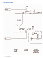
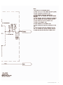
GE Healthcare
GrandStand System
Instructional Manual
GrandStand Modular
Membrane Systems
28-9335-29 AA
Important user information
Users must read this entire manual to fully understand the safe
use of GrandStand™ modular membrane systems.
Terms and conditions of sale
Unless otherwise agreed to in writing, all goods and services are
sold subject to the terms and conditions of sale of the company
within the GE Healthcare group that supplies them. You can
request a copy of these terms and conditions from GE Healthcare.
Should you have any comments on this product, please notify:
GE Healthcare
Björkgatan 30
751 84 Uppsala
Sweden
2
User Manual 28-9335-29 AA
Table of contents
Chapter 1—System Documentation and Safety
About this user guide
Audience
Where to find more information
System documentation
Material compliance
Safety compliance and design standards
Safety
Warning flags
Warning symbols
Safety warnings
5
5
5
5
5
5
5
6
6
6
Chapter 2—System Description
Introduction
Electrical system
Chemical compatibility
Hardware high pressure shut-off
Weights and dimensions
8
8
9
9
9
Chapter 3—Photographic System Tour
GrandStand system modular accessories
Data acquisition enclosure
Cable connection key
Flow meter
Temperature sensor
Pressure indicators
Feed line pressure indicator
Conductivity sensor
UV sensor
Permeate pump
SIP kit
Four position HF expansion kit
Kvick flow cassette kits
21
22
22
23
23
24
24
25
26
26
27
27
28
Chapter 4—Using the Membrane System
Introduction
Data aquisition operating system
Workflow
29
29
29
Chapter 5—System Preparation
General
Checking pump oil
System installation
Stating the system
Cartridge installation
New cartridge rinsing procedures
Clean water flux determination
Pressure hold and integrity tests
Processing
30
30
30
31
31
31
32
32
33
User Manual 28-9335-29 AA
3
Chapter 6—System Cleaning and Storing
Cleaning
Short-term storage
Long-term storage
Storage conditions
34
34
34
34
Chapter 7—Troubleshooting
Troubleshooting guide
35
Chapter 8—Maintenance
Parts
Inspection
Maintenance
General
Cleaning before maintenance/service
Component maintenance
Replacement of fuses
Instrumentation calibration
Voiding of warranty
Disassembly and assembly
Periodic maintenance
36
36
36
36
36
36
36
37
37
37
37
Chapter 9—Service and Training
Service
Training
38
38
Appendix
Membrane system label
Membrane system warning labels
Health and Safety Declaration/Liability Form
4
User Manual 28-9335-29 AA
39
39
39
Chapter 1
System Documentation and Safety
About this user guide
This user guide describes how to use GE Healthcare GrandStand™
membrane systems safely. The systems described in this guide
include GrandStand Modular systems (models 450 and 550)
Hereafter, this user guide refers to these systems as the membrane
system.
Audience
This user guide addresses the needs of scientists, process
engineers, and technicians who operate pilot-scale and
production-scale cross flow systems. The level of information
in this guide assumes the user possesses basic laboratory
and technical skills. The user should have the knowledge and
documentation to operate safely any user-supplied equipment
connected to the membrane system. If you need assistance
with the instructions in this guide, contact GE Healthcare for
more information.
Where to find more information
In the USA, you can contact our customer and technical support
teams by calling 1-800-526-3593. Outside of the USA, you can
contact your local GE Healthcare representative using the
telephone numbers listed at the back of this user guide. You
can also receive customer and technical support by emailing
us at these addresses:
Technical Support: [email protected]
System documentation
In addition to this user guide, you receive binders containing
specific documentation for the membrane system such as:
general specification, equipment list, P&ID, spare parts list,
inspection and test plan, inspection reports, functional test
report, installation test report, calibration and performance
certificates, panel layout, electrical schematics, I/O list and
material specifications.
Safety compliance and design
standards
GE Healthcare designed the system for electrical installation in
accordance with the prevailing standards in the country of
destination. CE marked membrane systems (standard and custom
systems) comply with EU directives and standards described in
the system documentation. The compliance with the directive is
valid under the condition that you install‚ operate and maintain
the membrane system according to the system documentation
and this user guide. To maintain compliance‚ use only spare parts
approved or supplied by your local GE Healthcare representative.
Safety
Anyone who works with the membrane system should read,
understand, and follow the instructions in this user guide
before using the system. If any operator does not understand
an instruction, they should stop working with the membrane
system and contact GE Healthcare for guidance. You should
save these instructions and make them available to all users of
the membrane system.
GE Healthcare designed the membrane system for pilot- and
production-scale filtration of biological solutions under the
conditions stated in this user guide. If you use the membrane
system in a manner not specified by GE Healthcare, you may
impair the protection provided by the unit.
When using cross flow equipment, the potential exists for
personal injury unless you follow established safety procedures.
When using GE Healthcare products, you should follow OSHA1,
federal, state, and/or local safety regulations for equipment
installation and operation. You should follow your company’s
safety regulations. You should follow the specific safety instructions
provided in this user guide and any original equipment manufacturer
user guides provided with your system.
Only qualified personnel with training, who understand the
operating instructions, should install, operate, maintain, and
inspect the membrane system.
Material compliance
The system documentation describes the design and materials
of construction of the membrane system. The wetted materials of
construction in the membrane system are recognized as safe for
use in food and drug-handling equipment as described for Good
Manufacturing Practice by the U.S. Food and Drug Administration.
You should review the system documentation to ensure the
system is suitable for your needs and specific application.
1
In the United States, OSHA is the Occupational, Safety, and Health Administration.
User Manual 28-9335-29 AA
5
Risk assessment
GE Healthcare designed and manufactured this system to
provide a high level of personal safety. The level of risk, however,
is dependent on the application and environment in which the
membrane system operates. To ensure safe use, you should
perform a risk assessment. The risk assessment should examine
your specific application and use environment. The assessment
should result in user-generated safety instructions—over and
above those provided by GE Healthcare—for installation,
operation, and maintenance.
Warning flags
This user guide uses a warning symbol and blocks of text to provide
safety warnings:
® Safety
WARNING: A safety warning flag describes conditions
or actions that can cause bodily harm and describes
how to avoid the risk. You must follow the warning
statement for safe operation of the membrane system.
Warning symbols
The membrane hardware uses warning symbols to warn operators
of potentially harmful conditions or actions. The appendix includes
examples and descriptions of the equipment warning symbols
used on the membrane system.
Safety warnings
WARNING
The maximum operating pressure of the system’s process
equipment and process lines is 4.1 barg (60 psig). If this pressure
is exceeded during integrity testing, equipment failure and bodily
injury can result. To ensure proper operation, and to prevent
equipment failure and bodily injury, do not exceed an air inlet
pressure 6 barg (90 psig) to the process lines during integrity
testing.
For the membrane system, the maximum operating pressure is
4.1 barg (60 psig). Wear the appropriate personal protection
devices when testing the system.
If a cross flow system leaks, it can release potentially hazardous
process fluids or cleaning fluids, causing bodily harm. To prevent
leaks and the release of potentially hazardous fluids, limit feed
pressure to 4.1 barg (60 psig) for membrane systems. Isolate and
depressurize the system before disassembling it. Periodically
inspect the system’s gaskets, seals, and connections for wear and
damage. Wear the appropriate personal protection devices and
clothing when operating and cleaning the system.
6
User Manual 28-9335-29 AA
WARNING
Membrane systems accept membrane cassettes or hollow fiber
cartridges depending on the model. Using cassettes or cartridges
without opening the packing properly can expose you to potentially
hazardous solutions. Read the safety instructions provided with
your membrane cassette or hollow fiber cartridge and follow the
instructions when opening the package.
WARNING
Using tap water to flush or rinse your membrane system can plug
the pores of the membrane with the relatively large particulates
(rust, dirt, minerals, bacteria, etc.) found in tap water. To prevent
plugging the pores of the membrane, always use 0.2-Ìm filtered or
water-for-injection (WFI) when rinsing or flushing the membrane
system, or when making up cleaning solutions or adding dilution
water to process fluids. In this user guide, the term clean water
means 0.2-Ìm filtered water or WFI.
WARNING
Data Logging accessories do not offer automatic process control.
Hence many users normally establish pump curves for the system
configuration they plan to use. By establishing a pump curve, they
can quickly and accurately set the pump speed to achieve the
recommended flow rate during processing. To determine the flow
rate without a pump curve, you would have to disconnect the
retentate line and measure the flow rate using a graduated cylinder
and stopwatch. If you need help in developing a pump curve,
contact GE Healthcare technical support team.
WARNING
Placing objects or fingers into valves‚ rotating pumps‚ fans or
other moving parts, can damage the equipment and cause bodily
harm. Do not place objects or fingers into valves‚ rotating pumps‚
fans or other moving parts. See the original equipment user guide
if you must work on or adjust these components.
WARNING
Moving a system without observing safety procedures can result
in the system tipping over and causing bodily injury and death.
Before moving the system, clean it, shut it down, and disconnect
all process and utility lines. If present on the system, observe the
warning labels concerning system moving and stability. See the
appendix for examples and descriptions of the warning labels
used on the membrane system.
WARNING
If you are exposed to infectious liquids originating from the system,
bodily harm can result. To prevent illness or any other effect from
infectious liquids‚ always maintain a safe distance from the system
during drainage or other activities that may involve splashing.
Also use appropriate personal protective equipment as described
in your company’s safety procedures.
WARNING
WARNING
Some membrane systems outfitted with the SIP accessory
module can be steam sterilized. If you touch piping and other
system components during steaming, burns can result. Do not
touch the system until you are sure that it can be done without
risk‚ when all components in the system have reached the normal
working temperature range. Special attention should be given to
the parts that are marked as hot or cold with signs described in
the appendix.
If cabinet doors, equipment covers, and safety guards are not
closed during operation, equipment damage and bodily harm can
result. To prevent equipment damage and bodily harm, properly
close cabinet doors, equipment covers, and safety guards before
starting the membrane system.
WARNING
If you are exposed to excessively high noise levels, bodily
harm can result. Check for warning signs in your work area,
and warning symbols on the membrane system indicating you
need to wear hearing protection. Wear hearing protection if
required to avoid bodily harm.
User Manual 28-9335-29 AA
7
Chapter 2
System Description
Introduction
GE Healthcare manufactures standard GrandStand Modular
systems. Standard GrandStand systems include these:
Ordering information
Code number
Catalog number
Description
Base System
28-4005-31
28-4005-32
28-4004-48
28-4004-49
28-4004-53
28-4004-54
GSMRLP550SYS1
GSMRLP450SYS1
GSMRLP550380V1
GSMRLP450380V1
GSMRLP550440V1
GSMRLP450440V1
GrandStand 550 Mod Sys 220VAC
GrandStand 450 Mod Sys 220VAC
GrandStand 550 Mod Sys 380VAC
GrandStand 450 Mod Sys 380VAC
GrandStand 550 Mod Sys 440VAC
GrandStand 450 Mod Sys 440VAC
Includes one set of documentation. Additional sets of documents can be supplied at an additional cost.
These systems include membrane cassette and hollow fiber
cartridge versions.
The membrane systems enable users to separate, concentrate,
and/or diafilter biological solutions with precision.
These systems come configured for membrane cassettes or
hollow fiber cartridges. By using conversion kits and rearranging
components, GE Healthcare representatives can convert some
standard membrane systems from a cassette system to a hollow
fiber system or vice versa.
System types
The data aquisition accessories do not automatically monitor
and regulate the membrane process control equipment. The
operator must manually operate the pumps and valves and
monitor the process conditions. The data aquisition accessories
do collect process data for later analysis and display when
exported to a computer with Microsoft® Excel.
Electrical system
Main power supply
The system label on the membrane system provides the
power requirements and consumption information. The
power consumption on the system label states the maximum
amperage consumption during full load of the equipment.
The system documentation also provides additional power
requirement information for proper operation of the system.
When replacing a damaged power cable, use a replacement
cable of the same type and dimensions.
8
User Manual 28-9335-29 AA
® Safety
WARNING: If the power supply you use is not grounded to
earth, equipment damage and bodily injury can result. To
avoid equipment damage and bodily injury, always connect
the system to a grounded (protected earth) power supply.
Review local electrical code details to ensure that the type of
power cable and other features are compliant.
Fuses
The membrane system main power supply is equipped with a
circuit breaker inside the cabinet. The system documentation
and the original equipment user guides supply information on
internal power supply and instrument fuses.
Power failure and back-up
If the control system loses electrical power, the membrane system
pumps stop. But the system may remain pressurized. The data
collected during the run is saved up to the last autosave, which
by default occurs every five minutes.
You should use an uninterrupted power supply (UPS) for the
computer system used to log data to avoid the loss of data
during a power failure.
® Safety
WARNING: During a power failure, or if the emergency stop
button is pressed, the system may remain pressurized.
Opening a line or vessel at this point could result in the
release of potential hazardous process or cleaning fluid,
and cause bodily harm. When recovering from a power
failure or emergency shutdown, ensure all lines and vessels
are depressurized before opening them up.
Emergency stop
GrandStand™ 450 system specifications
The membrane systems are equipped with one red emergency
stop button. Pushing the red emergency stop button cuts power
to all electrically-powered equipment and stops the system. You
can also use the main switch‚ to quickly stop the system. If there
is no risk of personal injury, use the normal shut down procedure
to shut the system down.
Base system
GrandStand 450
Weight (approximate)
1576 lbs (715 kg)
Chemical compatibility
All wetted parts have specific chemical resistances. See the system
documentation for additional information. You must ensure the
suitability of the process chemicals you use. You must consider
the compatibility of the wetted parts and your process chemicals
so that no negative interaction takes place, and so that your
process chemicals do not damage the system components,
compromising the safety of the system. Contact your local
GE Healthcare representative if you are not sure of the
compatibility of your chemicals.
Materials of Construction
Frame
304 stainless steel
Fluid path
316 L stainless steel
Fluid path surface finish
< 20 Ra μ in. (0.5 Ra μm)
Kvick Flow holder surface finish
Front and back plate
< 25 Ra μ in. (0.6 Ra μm)
Feed, retentate, permeate ports
CIP tank
15 gal. Polypropylene (56.7 L)
Pump Type
Rotary lobe
Max Pump Flow rate
120 L/min@ 30 psig (2.07 bar)
O-rings, gaskets, valve diaphragms
EPDM
System dead volume*
9.5 L (2.5 gal)
Power requirements
GSMRLP450 SYS
220 VAC 3 Phase 50/60 Hz
® Safety
WARNING: If you use chemicals that are not compatible with
the wetted parts of your system, equipment and product
damage can result. Equipment failure leading to leaks and
bodily injury can result. To avoid equipment damage and bodily
injury, do not use incompatible chemicals in the membrane
system. All wetted parts have specific chemical resistances.
See the system documentation for additional information.
Hardware high pressure shut-off
system
< 20 Ra μ in. (0.5 Ra μm)
GSMRLP450 380V
380 VAC 3 Phase 50/60 Hz
GSMRLP450 440V
440 VAC 3 Phase 50/60 Hz
GrandStand™ 550 system specifications
Base system
GrandStand 550
Weight (approximate)
1876 lbs (851 kg)
® Safety
Materials of Construction
WARNING: If you disconnect the system’s hardware-driven,
high-pressure shut-off safety system, overpressurization can
lead to equipment damage, or the unexpected release of pressure
or process and cleaning fluids, leading to bodily injury. To
avoid equipment damage or bodily injury, do not disconnect
the system’s hardware high pressure shut-off system.
Frame
304 stainless steel
Fluid path
316 L stainless steel
Fluid path surface finish
< 20 Ra μ in. (0.5 Ra μm)
Kvick Flow holder surface finish
Front and back plate
< 25 Ra μ in. (0.6 Ra μm)
When the pressure exceeds the limit of the system, the hardware
safety device will shut down the pumps and valves directly (not
via the control system.) Factory setting is 45 psig (3.06 barg).
Before restarting the system, determine the cause of overpressurization. This is usually a result of a flow restriction in
the retentate line or an increase in the recirculation pump speed.
Make an appropriate adjustment in the system controls to avoid
over-pressurization.
Filter matrix/spool combinations
Use of a broad range of HF filters is enabled through a
combination of swing elbows and piping spools. See filter
housing/pipe spools table and HF filters/piping spools drawing
for elbow orientation and spool piece/filter combination for the
HF filter selected.
Feed, retentate, permeate ports
< 20 Ra μ in. (0.5 Ra μm)
CIP tank
30 gal. Polypropylene (113.5 L)
Pump Type
Rotary lobe
Max Pump Flow rate
400 L/min@ 30 psig (2.07 bar)
O-rings, gaskets, valve diaphragms
EPDM
System dead volume*
18.9 L (5 gal)
Power requirements
GSMRLP550 SYS
220 VAC 3 Phase 50/60 Hz
GSMRLP550 380V
380 VAC 3 Phase 50/60 Hz
GSMRLP550 440V
440 VAC 3 Phase 50/60 Hz
*Approximate base system without tank or filter cartridge
Note: To determine minimum working volume, add volume of filter holder,
tank working volume to system dead volume.
User Manual 28-9335-29 AA
9
GrandStand 550 System
7' 0"
2134 mm
2' 5 1/2"
749 mm
6' 10 3/16"
2088 mm
10
User Manual 28-9335-29 AA
User Manual 28-9335-29 AA
11
GrandStand 450 System
6' 3"
1905 mm
2' 4 1/2"
724 mm
6' 6 1/2"
1993 mm
12
User Manual 28-9335-29 AA
User Manual 28-9335-29 AA
13
GrandStand 550 System
14
User Manual 28-9335-29 AA
User Manual 28-9335-29 AA
15
GrandStand 450 System
16
User Manual 28-9335-29 AA
User Manual 28-9335-29 AA
17
GrandStand 450 system housing and pipe spools dimensions
Dimensions
housing
Length
(in (cm))
Diameter
(in (cm))
Permeate
ports (in (cm))
Feed/Retentate
ports (in (cm))
Drain
port (SIP)
Vent
Cartridge
port (SIP) size (in (cm))
2 2”x1 1/2”
reducers
Total length
with reducers
45
35
35 SMO-DP
45 SMO-DP
35 STM
65
65 MSM-DP
152 M
55
55 SMO-DP
35 (2 in series)
35 SMO-DP
19.8 (50.3)
14.0 (35.6)
14.7 (37.3)
20.8 (52.8)
17.1 (43.4)
28.8 (73.2)
29.8 (75.7)
32.0 (81.3)
26.5 (67.3)
27.3 (69.3)
28.0 (71.1)
29.4 (74.7)
4.24 (10.8)
3.0 (7.6)
3.6 (9.1)
4.5 (11.4)
3.6 (9.1)
4.25 (10.8)
4.5 (11.4)
6.63 (16.8)
3.0 (7.6)
3.6 (9.1)
3.0 (7.6)
3.6 (9.1)
1.5 (3.8)
1.5 (3.8)
1.5 (3.8)
1.5 (3.8)
1.5 (3.8)
1.5 (3.8)
1.5 (3.8)
1.5 (3.8)
1.5 (3.8)
1.5 (3.8)
1.5 (3.8)
1.5 (3.8)
2.0 (5.1)
1.5 (3.8)
1.5 (3.8)
2.0 (5.1)
1.5 (3.8)
2.0 (5.1)
2.0 (5.1)
2.0 (5.1)
1.5 (3.8)
1.5 (3.8)
1.5 (3.8)
1.5 (3.8)
X-X-X
X-X-X
0.5
0.5
0.5
X-X-X
0.5
X-X-X
X-X-X
0.5
X-X-X
0.5
X-X-X
X-X-X
X-X-X
X-X-X
0.5
X-X-X
X-X-X
X-X-X
X-X-X
X-X-X
X-X-X
X-X-X
19.8 (50.3)
14.0 (35.6)
14.7 (37.3)
20.8 (52.8)
17.1 (43.4)
28.8 (73.2)
29.8 (75.7)
32.0 (81.3)
26.5 (67.3)
27.3 (69.3)
28.0 (71.1)
29.4 (74.7)
6
6
6
6
6
6
6
19.8 (50.3)
14.0 (35.6)
14.7 (37.3)
20.8 (52.8)
17.1 (43.4)
28.8 (73.2)
29.8 (75.7)
32.0 (81.3)
26.5 (67.3)
27.3 (69.3)
28.0 (71.1)
29.4 (74.7)
29.6 (75.2)
39.6 (100.6)
34.2 (86.9)
3.6 (9.1)
4.24 (10.8)
3.6 (9.1)
1.5 (3.8)
1.5 (3.8)
1.5 (3.8)
1.5 (3.8)
2.0 (5.1)
1.5 (3.8)
0.5
X-X-X
0.5
0.5
X-X-X
0.5
29.6 (75.2)
39.6 (100.6)
34.2 (86.9)
6
6
29.6 (75.2)
39.6 (100.6)
34.2 (86.9)
41.6 (105.7)
4.5 (11.4)
1.5 (3.8)
2.0 (5.1)
0.5
X-X-X
41.6 (105.7)
-
41.6 (105.7)
44.5 (113.0)
51.5 (130.8)
52.7 (133.9)
54.8 (139.2)
3.0 (7.6)
4.25 (10.8)
4.5 (11.4)
6.63 (16.8)
1.5 (3.8)
1.5 (3.8)
1.5 (3.8)
1.5 (3.8)
1.5 (3.8)
2.0 (5.1)
2.0 (5.1)
2.0 (5.1)
X-X-X
X-X-X
0.5
X-X-X
X-X-X
X-X-X
X-X-X
X-X-X
44.5 (113.0)
51.5 (130.8)
52.7 (133.9)
54.8 (139.2)
6
-
44.5 (113.0)
51.5 (130.8)
52.7 (133.9)
54.8 (139.2)
(2 in series)
55 STM
45 (2 in series)
35 STM
(2 in series)
45 MSM-DP
(2 in series)
75
85
85 MSM-DP
154 m
GrandStand 450 system housing and pipe spools dimensions continued
Dimensions
housing
Not pipe spool
required (in (cm))
Pipe spool
6.5” (in (cm))
Pipe spool
13.5” (in (cm))
Using both
spools (in (cm))
Center to center
swing elbows (in (cm))
Angle
45
35
35 SMO-DP
45 SMO-DP
35 STM
65
65 MSM-DP
152 M
55
55 SMO-DP
35 (2 in series)
35 SMO-DP
-
40.5 (102.9)
41.9 (106.4)
42.3 (107.4)
43.3 (110.0)
45.5 (115.6)
46.0 (116.8)
46.8 (118.9)
-
39.8 (101.1)
40.0 (103.4)
40.0 (103.4)
40.8 (103.6)
43.1 (109.5)
-
15.0 (38.1)
14.8 (37.6)
14.1 (35.8)
14.0 (35.6)
11.7 (29.7)
12.5 (31.8)
11.5 (29.1)
9.3 (23.6)
8.8 (22.4)
8.0 (20.3)
14.3 (36.3)
12.9 (32.8)
20.36
22.33
28.21
28.96
43.01
38.62
44.05
54.46
56.63
60.00
28.65
36.27
-
42.1 (106.9)
46.1 (117.1)
46.7 (118.6)
-
-
12.7 (32.3)
8.7 (22.1)
8.1 (20.6)
37.46
57.06
59.59
41.6 (105.7)
-
-
-
13.2 (33.5)
34.41
75
85
85 MSM-DP
44.5 (128.3)
51.5 (130.8)
52.7 (133.9)
-
-
-
4.3 (10.9)
3.3 (8.4)
2.1 (5.3)
154 m
54.8 (139.2)
-
-
-
0
74.41
78.10
Don’t use
swing elbows
Don’t use
swing elbows
(2 in series)
55 STM
45 (2 in series)
35 STM
(2 in series)
45 MSM-DP
(2 in series)
18
User Manual 28-9335-29 AA
GrandStand 550 system housing and pipe spools dimensions
Dimensions
housing
Length
(in (cm))
Diameter
(in (cm))
Permeate
ports (in (cm))
Feed/Retentate
ports (in (cm))
Drain
port (SIP)
Vent
Cartridge
port (SIP) size (in (cm))
2 2”x1 1/2”
reducers
Total length
with reducers
45
35
35 SMO-DP
45 SMO-DP
35 STM
65
65 MSM-DP
152 M
55
55 SMO-DP
35 (2 in series)
35 SMO-DP
19.8 (50.3)
14.0 (35.6)
14.7 (37.3)
20.8 (52.8)
17.1 (43.4)
28.8 (73.2)
29.8 (75.7)
32.0 (81.3)
26.5 (67.3)
27.3 (69.3)
28.0 (71.1)
29.4 (74.7)
4.24 (10.8)
3.0 (7.6)
3.6 (9.1)
4.5 (11.4)
3.6 (9.1)
4.25 (10.8)
4.5 (11.4)
6.63 (16.8)
3.0 (7.6)
3.6 (9.1)
3.0 (7.6)
3.6 (9.1)
1.5 (3.8)
1.5 (3.8)
1.5 (3.8)
1.5 (3.8)
1.5 (3.8)
1.5 (3.8)
1.5 (3.8)
1.5 (3.8)
1.5 (3.8)
1.5 (3.8)
1.5 (3.8)
1.5 (3.8)
2.0 (5.1)
1.5 (3.8)
1.5 (3.8)
2.0 (5.1)
1.5 (3.8)
2.0 (5.1)
2.0 (5.1)
2.0 (5.1)
1.5 (3.8)
1.5 (3.8)
1.5 (3.8)
1.5 (3.8)
X-X-X
X-X-X
0.5
0.5
0.5
X-X-X
0.5
X-X-X
X-X-X
0.5
X-X-X
0.5
X-X-X
X-X-X
X-X-X
X-X-X
0.5
X-X-X
X-X-X
X-X-X
X-X-X
X-X-X
X-X-X
X-X-X
19.8 (50.3)
14.0 (35.6)
14.7 (37.3)
20.8 (52.8)
17.1 (43.4)
28.8 (73.2)
29.8 (75.7)
32.0 (81.3)
26.5 (67.3)
27.3 (69.3)
28.0 (71.1)
29.4 (74.7)
6
6
6
6
6
6
6
19.8 (50.3)
14.0 (35.6)
14.7 (37.3)
20.8 (52.8)
17.1 (43.4)
28.8 (73.2)
29.8 (75.7)
32.0 (81.3)
26.5 (67.3)
27.3 (69.3)
28.0 (71.1)
29.4 (74.7)
29.6 (75.2)
39.6 (100.6)
34.2 (86.9)
3.6 (9.1)
4.24 (10.8)
3.6 (9.1)
1.5 (3.8)
1.5 (3.8)
1.5 (3.8)
1.5 (3.8)
2.0 (5.1)
1.5 (3.8)
0.5
X-X-X
0.5
0.5
X-X-X
0.5
29.6 (75.2)
39.6 (100.6)
34.2 (86.9)
6
6
29.6 (75.2)
39.6 (100.6)
34.2 (86.9)
41.6 (105.7)
4.5 (11.4)
1.5 (3.8)
2.0 (5.1)
0.5
X-X-X
41.6 (105.7)
-
41.6 (105.7)
44.5 (113.0)
51.5 (130.8)
52.7 (133.9)
54.8 (139.2)
3.0 (7.6)
4.25 (10.8)
4.5 (11.4)
6.63 (16.8)
1.5 (3.8)
1.5 (3.8)
1.5 (3.8)
1.5 (3.8)
1.5 (3.8)
2.0 (5.1)
2.0 (5.1)
2.0 (5.1)
X-X-X
X-X-X
0.5
X-X-X
X-X-X
X-X-X
X-X-X
X-X-X
44.5 (113.0)
51.5 (130.8)
52.7 (133.9)
54.8 (139.2)
6
-
44.5 (113.0)
51.5 (130.8)
52.7 (133.9)
54.8 (139.2)
(2 in series)
55 STM
45 (2 in series)
35 STM
(2 in series)
45 MSM-DP
(2 in series)
75
85
85 MSM-DP
154 m
GrandStand 550 system housing and pipe spools dimensions continued
Dimensions
housing
Not pipe spool
required (in (cm))
Pipe spool
6.5” (in (cm))
Pipe spool
13.5” (in (cm))
Using both
spools (in (cm))
Center to center
swing elbows (in (cm))
Angle
45
35
35 SMO-DP
45 SMO-DP
35 STM
65
65 MSM-DP
152 M
55
55 SMO-DP
35 (2 in series)
35 SMO-DP
-
40.5 (102.9)
41.9 (106.4)
42.3 (107.4)
43.3 (110.0)
45.5 (115.6)
46.0 (116.8)
46.8 (118.9)
-
39.8 (101.1)
40.0 (103.4)
40.0 (103.4)
40.8 (103.6)
43.1 (109.5)
-
15.0 (38.1)
14.8 (37.6)
14.1 (35.8)
14.0 (35.6)
11.7 (29.7)
12.5 (31.8)
11.5 (29.1)
9.3 (23.6)
8.8 (22.4)
8.0 (20.3)
14.3 (36.3)
12.9 (32.8)
20.36
22.33
28.21
28.96
43.01
38.62
44.05
54.46
56.63
60.00
28.65
36.27
-
42.1 (106.9)
46.1 (117.1)
46.7 (118.6)
-
-
12.7 (32.3)
8.7 (22.1)
8.1 (20.6)
37.46
57.06
59.59
41.6 (105.7)
-
-
-
13.2 (33.5)
34.41
75
85
85 MSM-DP
44.5 (128.3)
51.5 (130.8)
52.7 (133.9)
-
-
-
4.3 (10.9)
3.3 (8.4)
2.1 (5.3)
154 m
54.8 (139.2)
-
-
-
0
74.41
78.10
Don’t use
swing elbows
Don’t use
swing elbows
(2 in series)
55 STM
45 (2 in series)
35 STM
(2 in series)
45 MSM-DP
(2 in series)
User Manual 28-9335-29 AA
19
20
User Manual 28-9335-29 AA
Chapter 3
Photographic System Tour
GrandStand™ system modular
accessories
Front
B
C
E
A. Data Acquisition Enclosure
B. Flow Meter (requires A)
C. Pressure Sensor (requires A)
D. Temperature Sensor (requires A)
E. Conductivity Sensor (requires A)
F. UV Sensor (requires A)
G. Permeate Pump
H. SIP Kit
I. 4 Position HF Kit
J. Kvick Flow Cassette Kit (replaces HF filters)
Display
A
C
D
H
G
Back
C
E
F
I
J
Fig 4. General arrangement of accessory options.
The GS550 is shown. GS450 is similar (except for
4 position option). Permeate side tubing removed
for simplicity.
User Manual 28-9335-29 AA
21
Data acquisition enclosure
Facing the front of the GrandStand system (side where motor
and VFD are located), mount the data acquisition enclosure to
the horizontal frame using the threaded studs and nuts provided on the system. Ref item A location in the system
schematic. The enclosure is plugged directly into a wall outlet.
The enclosure provides 24VDC power to the data acquisition
modules. See data acquisition connectology diagram for
power and data collection positions for each of the modules.
Cable connection diagram
Cable connection key
Yellow cables are power cables
A is for enclosure power cord
B is for permeate pump power cord
C is for conductivity meter power
D is for UV sensor power
E is for retentate flow meter power
Purple cables are data transmission cables
J1 is for feed temperature sensor
J2 is a spare
J3 is for feed pressure indicator
J4 is for retentate flow meter readout
J5 is for retentate pressure indicator
J6 is for permeate pressure indicator
J7 is for UV sensor
J8 is for conductivity sensor
22
User Manual 28-9335-29 AA
Flow meter
Temperature sensor
The retentate flow meter is mounted on the retentate line
where indicated on the installation guide. Locate the piping
spool piece, remove the tri-clover clamps and gaskets and
spool piece. Replace the spool piece with the flow meter
positioning the flow meter readout below the retentate line
and facing the back of the system. Reassemble the tri-clover
clamps and gaskets and tighten sufficiently to seal the
process piping. Connect power and data transmission
cables. Position the cables along the system frame from the
flow meter to the data acquisition enclosure and secure with
cable ties.
The temperature sensor is mounted vertically on the feed line
where indicated on the installation guide. Locate the piping
end cap, remove the tri-clover clamps and gasket. Replace
the end cap with the temperature sensor. Reassemble the
tri-clover clamps and gaskets and tighten sufficiently to seal
the process piping. Connect data transmission cable. Position
the cable along the system frame from the sensor to the data
acquisition enclosure and secure with cable ties.
User Manual 28-9335-29 AA
23
Pressure indicators
The pressure indicators are mounted on the feed, retentate
and permeate lines (as purchased) where indicated on the
installation guide. For the feed line, the pressure indicator
replaces the pressure gauge. Remove the tri-clover clamp,
gasket and pressure gauge. Replace the pressure gauge
with the pressure indicator and reassemble with the clamp
and gasket.
Feed line pressure indicator
For the retentate line, the pressure indicator is placed at the
end of the retentate piping to facilitate local readout viewing.
Remove the tri-clover clamp, end cap and gasket. Replace
the end cap with the pressure indicator and reassemble with
the clamp and gasket. The end cap may be is used to
replace the pressure gauge on the retentate line above the
filter positions. The permeate pressure indicator is assembled
within the permeate line when the system includes a
permeate pump kit or may be assembled in a customer
supplied permeate line if properly supported. When
reassembling tri-clover clamps and gaskets, tighten
sufficiently to seal the process piping. Connect data
transmission cables as indicated in the connection key
above. Position the cable along the system frame from
the sensor to the data acquisition enclosure and secure
with cable ties.
24
User Manual 28-9335-29 AA
Conductivity sensor
The conductivity sensor is mounted on the permeate line
supplied as part of the kit where indicated on the installation
guide. The readout is mounted on the frame in position
E adjacent to the data acquisition enclosure using frame
mounted studs and nuts. Connect the power and data
transmission cables as indicated in the cable connection
diagram above. Position the cables along the system frame
from the sensor to the data acquisition enclosure and secure
with cable ties.
User Manual 28-9335-29 AA
25
UV sensor
Permeate pump
The UV sensor is mounted on the permeate line supplied as
part of the kit where indicated on the installation guide.
Connect the data transmission cables as indicated in the
cable connection diagram above. Position the cables along
the system frame from the sensor to the data acquisition
enclosure and secure with cable ties.
The permeate pump is mounted on the frame where
indicated on the installation guide position G, below the
CIP tank. Secure the kit plate with the studs and nuts found
on the frame. The pump selected rests on the plate and
connects to the data acquisition enclosure as indicated in
the connection diagram. Position the cable along the system
frame from the pump to the data acquisition enclosure and
secure with cable ties.
The permeate pump is typically used to restrain the flow
from microfiltration cartridges to a preset level. When
cartridges are arranged in parallel, the top permeate lines
can be manifolded to a single tube passing through the
pumphead. When cartridges are arranged in series, the
flows must be segregated using multiple heads on the
permeate pump. Consult GE Healthcare Technical Support
for specific recommendations.
26
User Manual 28-9335-29 AA
SIP kit
Four position HF expansion kit
The SIP kit is installed in position H of the installation guide
diagram. Loosen and remove the tri-clover clamp, gasket and
drain valve from the end of the feed line. Position the steam
trap between the drain valve and the feed line low point.
Install the steam trap and drain valve using the tri-clover
clamps and gaskets. When reassembling tri-clover clamps
and gaskets, tighten sufficiently to seal the process piping.
The four position HF expansion kit is mounted to the feed
and retentate lines to the left of the 2 filter positions already
installed as indicated in the installation guide diagram. Each
filter position includes inlet and outlet valves and piping spool
pieces. Assemble each position to the feed and retentate lines
using tri-clover clamps and gaskets, using this photo as a
guide. Each position has at the retentate side a set of two
180° elbows and one 90° elbow. The elbow assemblies are
configured as indicated in the housing and pipe spool
matrix on page 19 of this manual. When assembling triclover clamps and gaskets, tighten sufficiently to seal the
process piping.
Note: Second set of valves and steam traps are required for the
permeate side of the stainless steel housing(s) and SIP cartridge
intended for your process. Stainless steel housing and permeate
side connections must be purchased separately. Refer to the
Steam Sterilization Handbook (18-1174-71 AA) for more details
on proper installation and operation of SIP hollow fiber cartridges.
User Manual 28-9335-29 AA
27
Kvick flow cassette kits
The Kvick Flow cassette kits are installed in position K as
indicated on the installation guide diagram. In order to install
the Kvick Flow kits, the hollow fiber cartridge position spool
pieces are removed. The frame structural components of the
kit are installed using the studs and nuts provided on the
frame. GrandStand 450 is limited to one set of 2 Kvick
Flow holders and therefore can accommodate one (1) kit.
Grandstand 550 allows for 2, 4 or 6 holders therefore
accommodate one (1), two (2) or three (3) kits. Be sure to
secure the kits to the base and to the horizontal frame
component at the appropriate heights for the number of
kits installed.
The Kvick flow manual holder is mounted to the horizontal
plate for each kit.
Kvick Flow holder ports are connected to the system feed and
retentate lines using the manifold provided as part of the kit.
These are connected to the system such that the manifold is
positioned between the Kvick Flow holders, which face each
other. (see graphics below).
Fig 5. 450 Installation Diagram.
Fig 6. 550 Installation Diagram.
28
User Manual 28-9335-29 AA
Chapter 4
Using the Membrane System
Introduction
Systems with data acquisition accessories installed use software installed on a nonintegrated computer: the software
only provides data collection and data display functions.
Data acquisition operating
environment
Enclosure transfers data to computers under Microsoft
Windows NT 4.00, Windows 2000 or Windows XP, using the
English keyboard settings. Connect cable to RS232 port
according to instructions in documentation package.
Work flow
For data logging systems, you control the run manually. After
completing the run, you can transfer the data to a Microsoft
Excel spreadsheet.
User Manual 28-9335-29 AA
29
Chapter 5
System Preparation
General
System installation
This chapter describes the initial start-up and testing
procedures for membrane systems. The procedures below
assume you have installed the system in accordance with
the installation instructions in this guide and that the
personnel performing these tasks have the appropriate
knowledge of the system and the application.
The GrandStand™ System as shipped requires minor on-site
assembly and minimal effort to initiate operation. It is the
customer’s responsibility to follow all National and Local
codes pertaining to both plumbing and electrical connections.
GE Healthcare engineers test all membrane systems before
shipping. The system documentation contains the results of
the system tests.
1. Unpackage the system carefully. Some components,
such as the pressure gauges, are easily damaged if
handled roughly.
2. Install the pressure gauges with a gasket and tri-clamp
to the inlet and outlet manifolds.
Checking pump oil
3. Install any modular accessory kits that were purchased.
Read the pump user guide to ensure you understand its
operation and maintenance before using the system.
Ensure that the pump transmission is filled with lubricant.
4. Install the customer-supplied retentate and permeate
piping.
30
User Manual 28-9335-29 AA
5. Connect the AC inverter into local electrical power main
supply following all electrical codes and referring to AC
inverter manual. Failure to properly connect the inverter
can severely damage the inverter and/or motor. A qualified
electrician should perform this work and make sure the
pump is rotating properly.
Starting the system
New cartridge rinsing procedures
Ensure these items are complete before starting the system:
The following Quick Flush is more than adequate for glycerin
removal under most situations. Refer to page 5 of the GE
Healthcare Bio-Sciences Operating Guide for general
information about flushing glycerin from cartridges.
1. Connect main pump power supply according to section
“Electrical System Main Power Supply” on page 8.
2. Install any modular accessories according to the
instructions supplied with each kit.
3. Install your membrane cassette or hollow fiber cartridge
according to the instructions supplied with the cassette
or cartridge holder.
4. Turn the main switch to the ON position (refer to P&ID and
electrical drawings).
5. Power up computer if connected to data aquisition
enclosure after membrane system is on.
1. Close all valves.
2. Fill the clean-in-place (CIP) tank with 10,000 NMWC
ultrafiltered water or better. (GrandStand 550=30 gallon
(113 liters), GrandStand 450=15 gallons (56 liters)).
3. Open CIP feed valve 100% to flood the pump suction side.
4. Be sure that the permeate and retentate lines are directed
back to the CIP tank and secured. Permeate side valves
should be set in “open” position.
Cartridge installation
5. Open the retentate valve (s) 100% until all the air has
escaped from the system, then adjust to 20% open
(approximately 1 turn).
1. Place the cartridge on the outlet piping of the bottom
manifold, making sure that a tri-clamp gasket is
seated properly.
6. Push the FWD key on the AC Inverter.
2. Place a tri-clamp gasket on the top (retentate) port of
the cartridge.
3. Maintaining a firm grip on the cartridge, lower the top
manifold until the tri-clamp gasket is seated properly.
4. Still keeping a firm grip on the cartridge, clamp the inlet
and outlet of the cartridge with the supplied tri-clamps.
5. Install the permeate hoses, keeping in mind that the
permeate ports are not intended to support heavy valves,
flowmeters, or piping, as the resulting stress could damage
the cartridge housing. (Gaskets, tri-clamps, and adapters to
flexible tubing are supplied with the system; permeate
hoses are customer supplied).
WARNING
Before connecting power compare this system's specs with your
power supply main voltage, power phase and cycles per second.
7. Push the up arrow on the AC Inverter until the inlet pressure
reaches approximately 8 psig (0.55 barg).
8. Adjust the pump speed and retentate valve together until
inlet pressure (Pin) is 10 psig (0.69 barg) and outlet pressure
(Pout) is 6 psig (0.41 barg) for microfiltration cartridges. For
ultrafiltration cartridges use Pin of 15 psig (1.03 barg) and
Pout of 11 psig (0.76 barg). After 5 minutes reduce pressure
on microfiltration cartridge to Pin of 3 (0.21 barg), Pout of 2
(0.14 barg). Flow rates will depend on installed cartridges.
For example, two size 45 cartridges with 1.0 mm ID fibers
at 500 lpm flow will be approximately Pin of 10 psig (0.69
barg) and Pout of 6 psig (0.41 barg).
NOTE: The amount the retentate valve needs to be opened or how high the RPM
needs to be set will depend on cartridge and fiber configuration, larger diameter
fiber will require the valves to be more and a higher RPM.
9. Continue rinsing for at least 10 minutes.
10. Push the STOP key on the AC Inverter.
11. Close all the valves and allow the cartridge to soak for
at least 30 minutes.
12. Drain the system using the drain valve.
13. Repeat steps 2-11.
14. Drain the system using drain valve, keeping retentate
valve (s) open to allow air into the system.
User Manual 28-9335-29 AA
31
Clean water flux determination
Pressure hold and integrity tests
In order to evaluate cleaning processes, a baseline clean
water flux measurement should be established. Once
established, comparing water flux before and after process
runs will provide an idea of the effectiveness of the cleaning
procedure. Refer to Page 6 of the GE Healthcare Operating
Guide for sample water flux calculations.
Before using the system, check the filters (cassette and holder
or hollow fiber cartridges) for proper installation. Finally, check
the tightness of all sanitary clamps.
Microfiltration membranes are so highly permeable that
water flux testing requires low pressure operation and very
sensitive pressure monitoring. Consult GE Healthcare
Technical Support for recommendations.
1. Close all valves.
2. Fill the clean-in-place (CIP) tank with 10,000 NMWC
ultrafiltered water or better.
3. Open CIP feed valve 100% to flood the pump suction side.
4. Be sure that the permeate and retentate lines are directed
back to the CIP tank and secured.
Users normally check their cross flow systems for leaks by
pressurizing the system with water and observing any
leakage from process connections.
Users also check the integrity of membrane filters before
using them by pressurizing the system and measuring the
diffusion of air through the filters. If the diffusion rate meets
acceptance criteria, then the user is assured that the
membrane filters do not contain pinholes and are securely
mounted in the system.
GE Healthcare recommends that you complete air integrity
tests on the system filters before use.
Note: All GE Healthcare filter devices are tested for integrity
before shipment. It is prudent to test integrity before and
after each process cycle.
5. Open the retentate valve (s) 100% until all the air has
escaped from the system, then adjust to 20% open
(approximately 1 turn).
6. Push the FWD key on the AC Inverter.
7. Push the up arrow on the AC Inverter until the inlet
pressure reaches approximately 8 psig (0.55 barg).
8. Adjust the pump speed and retentate valve until Pin ~
10 psig (0.67 barg) and Pout ~ 6 psig (0.41 barg) for
microfiltration cartridges (15 psig (1.03 barg) in and
11 psig (0.76 barg) out for ultrafiltration cartridges).
NOTE: The amount the retentate valve needs to be opened or how high the RPM needs to
be set will depend on cartridge and fiber configuration, larger diameter fiber will require the
valves to be more and a higher RPM.
9. Record Pin, Pout, temperature, and the permeate flow rate.
(Permeate flow can be measured with a stopwatch and
graduate cylinder).
10. Push the STOP key on the AC Inverter.
11. Drain the system using drain valve.
32
User Manual 28-9335-29 AA
Processing
Since all feed streams behave differently, it is difficult to
specify exactly how to run the system. This section will
provide a starting point from which the path to successful
processing can be developed. Refer to page 7 of the GE
Healthcare Operating Guide for operating considerations.
It is a good idea to test the system using water (10,000
NMWC ultrafiltered or better) before processing valuable
feed solution.
1. Close all valves.
2. Be sure that there is ample feed solution to process in the
feed tank (customer supplied).
3. Open feed valve 100% to flood the pump suction side.
4. Be sure that the permeate and retentate lines are directed
to the appropriate destinations.
5. Open the retentate valve (s) 100% until all the air has
escaped from the system, then adjust 20% open (approximately 1 turn).
6. Push the FWD key on the AC Inverter.
7. Push the up arrow on the AC Inverter until the inlet pressure
reaches approximately 8 psig (0.55 barg).
8. Adjust feed flow and transmembrane pressure to suit
your process requirements. If performing a microfiltration
process, TMP will be governed by permeate flow
control options.
NOTE: The amount the retentate valve needs to be opened or how high the RPM
needs to be set will depend on cartridge and fiber configuration, larger diameter
fiber will require the valves to be more and a higher RPM.
9. Record Pin, Pout, temperature, and the permeate flow rate as
a function of time. (Permeate flow can be measured with a
stopwatch and graduate cylinder).
10. Push the STOP key on the AC Inverter.
11. Drain the system using drain valve.
12. With microfiltration cartridges it is common to restrict the
permeate flow to a pre-set level. Permeate flow control
can be regulated by a valve or peristaltic pump. This
practice promotes increased throughputs and
improved processing.
User Manual 28-9335-29 AA
33
Chapter 6
System Cleaning and Storing
Cleaning
To ensure that the membrane filtration system performs
properly —and to extend its service life—clean and store the
system as described below:
Cleaning the membrane filters—Membrane filters require
cleaning using specific cleaning solutions and procedures.
The membrane cassettes and hollow fiber cartridges are
normally cleaned while installed on the system. Recirculate
cleaning solutions through the membrane filters and either
leave them in the system for short-term storage or removed
them for long-term storage. To learn how to clean membrane
filters consult either the Hollow Fiber Operating Handbook
(18-1165-30 AB) or the Kvick Lab and Kvick Flow Cassettes
User Manual (18-1171-69 AG). These documents can be
requested from GE Technical Services.
WARNING
Do not drain system. Do not allow membranes to become
dried out during storage.
Long-term storage
To store the system more than 10 days, perform the cleaning
procedures summarized in the Cleaning section on page 34;
then follow these steps:
1. Fill the system with 0.5M NaOH and circulate for 10 to
15 minutes.
2. End the cycle and completely drain the system.
3. Disconnect all process lines from the system and blank-off
the connection points using sanitary end caps, gasket and
clamp. Remove flex tubing on permeate side.
Cleaning the exterior of the membrane system—After each
run, clean the exterior of the system to remove contaminates.
Wipe the exterior of the system down with clean water to
remove any buildup of process and cleaning solutions. Dry
the exterior components with a lint-free cloth.
4. Remove the membrane cassettes or hollow fiber cartridges
and store them according to their instructions.
Cleaning individual components—Some of the
components such as conductivity probes have special
cleaning requirements. Refer to the original manufacturer’s
user guides located in the system documentation to learn
about cleaning these components.
7. Disconnect all utility lines from the system.
Short-term storage
5. Shut down the computer system.
6. Switch the system’s main power switch to the OFF position.
8. System is now ready for storage.
9. After long-term storage, system may require several
cleaning cycles before use. Perform a calibration of all
monitors and perform a leakage test before putting the
system into production.
For short-term storage (less than ten days), perform the
cleaning procedures summarized above (Cleaning section on
page 34); then follow these steps:
Storage conditions
1. Fill the system with 0.1M NaOH and circulate for 10 to 15
minutes. The NaOH will prevent any bacterial growth inside
the system.
Temperature: -10 to 50°C
Relative humidity: 0 to 100%‚ non-condensing
2. End the cycle and shut down the computer system.
3. Switch the system’s main power switch to OFF.
4. Release back pressure valves.
34
User Manual 28-9335-29 AA
Storage requirements include these:
Chapter 7
Troubleshooting
Troubleshooting guide
If the membrane system does not work properly, consult the
troubleshooting guide (Table 1).
Table 1. Membrane system troubleshooting guide.
Symptom
Possible Cause
Solution
Process solution leaks from sanitary
connections
Sanitary connection gasket missing, worn,
damaged, improperly mounted, or wrong size
Replace worn, damaged, or improperly
sized gaskets
Sanitary clamp loose
Tighten sanitary clamp
Membrane filter is fouled
Clean the membrane filter
Obstruction in feed line or retentate line
Inspect lines for obstruction
Feed inlet in the membrane filter plugged
Switch feed and retentate lines to reverse
flow, and rinse with deionized water or WFI
Pump speed setting too high
Either open retentate valve to allow more
flow or reduce pump speed
Improperly seated or damaged gasket at
sanitary fitting
Locate leaking area by feeling air leak
with hand, or by applying soapy water and
looking for bubbles. Remove, inspect, and
reinstall sanitary fitting gaskets.
Faulty valve
Check integrity of valves and replace
as needed.
Feed pressure is too high
System leaks during integrity testing
User Manual 28-9335-29 AA
35
Chapter 8
Maintenance
® Safety
WARNING: Inspecting and maintaining the membrane
system without shutting it down, depressurizing it,
and disconnecting all utilities can result in bodily
injury from the accidental start-up of the pump or
unexpected release of pressure. To prevent bodily
injury, shut down the system, depressurize it, and
disconnect the utilities before inspecting and
maintaining the system.
Parts
The system documentation lists replacement parts and
spare parts.
Inspection
Periodically, based on use and applications, perform the
following inspections and maintenance:
• Inspect process piping and connections for damage
or leaks.
• Inspect electrical connections for proper fit.
• Inspect the sanitary connection gaskets for damage
or wear and replace the gaskets as needed.
• Inspect system components following the recommendations
in the original manufacturers’ user guides.
Membrane systems are designed to require a minimum of
service and maintenance. This chapter describes procedures
for sanitizing and cleaning-in-place for routine component
maintenance.
® Safety
WARNING: Only trained personnel‚ or personnel with
equivalent knowledge of similar equipment‚ should
complete system maintenance or service.
Cleaning before maintenance/service
Clean the system of infectious or aggressive fluids before
service or maintenance. Document the cleanliness by
completing a decontamination report. (You must supply
a decontamination report before a GE Healthcare service
technician can work on the system. The appendix includes
an example of a typical decontamination report entitled,
Heath and Safety Declaration/Liability Form.)
Make sure that the cleaning procedure flushes all possible
flow paths in the system. After cleaning‚ flush the entire
system with water or suitable liquid to remove the CIP
solution. (In some instances, you can use the system
instrumentation to monitor the removal of cleaning solution.)
Component maintenance
Maintenance
The OEM guides in the system documentation provide
preventative maintenance recommendations for each
major system component.
Lubricate and calibrate system components in accordance
with the recommendations in the original manufacturers’
user guides located in the system documentation.
Use only spare parts recommended or supplied by GE
Healthcare to maintain the proper performance of the
membrane system.
GE Healthcare recommends that you purchase preventative
maintenance services from GE Healthcare. Proper maintenance
ensures that the system performs in accordance with
GE Healthcare specifications.
Replacement of fuses
General
For maintenance on specific instruments, read and follow
the instructions in the OEM manuals in the system
documentation.
36
User Manual 28-9335-29 AA
® Safety
WARNING: If you attempt to replace a system fuse
without switching off the main power switch and
disconnecting the system from all electrical power
supplies, bodily injury can result. To prevent bodily
injury, switching off the main power switch and
disconnecting the system from all electrical power
supplies before replacing system fuses.
® Safety
Table 2. Membrane system maintenance recommendations
WARNING: If you replace system fuses with fuses of
a different rating or style, equipment damage or fire
hazards can result. To prevent equipment damage or
potential fire hazards, replace system fuses with the
same type and rating of fuse.
Period
Component
Maintenance
Before
each run
In-Line filters
Clean or replace filter cartridge
UV monitor
Set auto-zero
Test alarm
buzzer
Use instruction in control system
Weekly
Tubing and
connectors
Inspect the system for leaks
Monthly
Tubing,
connectors,
and sensors
Leakage test of the piping
system, and inspection of tubing
and sensors for internal coating,
rust, etc.
Pumps
Check oil level. Inspect for coating,
rust, etc. Refer to the pump
instruction manual in the system
documentation for specific
maintenance requirements
UV monitor
Replace the lamp when low
intensity or lamp failure is
indicated. Refer to the UV
monitor instruction manual in
the system documentation
Pumps
Replace wear components. Refer
to the pump instructions manual
in the system documentation
All components
Replace gaskets, O-rings, and
diaphragms
If a fuse repeatedly blows‚ shutdown the membrane
system main switch and contact your local
GE Healthcare representative.
Instrumentation calibration
For reliable performance‚ calibrate the system instrumentation
according to manufacturer’s recommendation and the
recommendations in Table 2.
Calibration compares the instrument to a known reference.
If instrument adjustments are necessary, GE Healthcare
recommends that you contact the instrument manufacturer
or GE Healthcare for help.
Voiding of warranty
Any warranty provided with the membrane system become
void if instruments are adjusted by anyone other than GE
Healthcare service personnel, the instrument manufacturer’s
service personnel, or personnel authorized by GE Healthcare.
Annually
or as
necessary
Disassembly and assembly
The operator must read and understand the instructions for
system components before removing and installing them.
Contact your local GE Healthcare representative for additional
information or help if needed.
® Safety
WARNING: Disassembling the membrane system
without shutting it down, depressurizing it, and
disconnecting all utilities can result in bodily injury
from the accidental start-up of the pump or unexpected
release of pressure. To prevent bodily injury, shut down
the system, depressurize it, and disconnect the utilities
before disassembling the system.
After assembly‚ you must test the piping system for
leaks at the maximum system pressure for continued
protection against injury risks due to water jets or
burst pipes (refer to leakage test in the system
documentation).
Periodic maintenance
The maintenance recommendations differ depending on
frequency of use. Hence, use the recommendation as a
guideline and develop your own maintenance schedule
based on use and experience (Table 2).
User Manual 28-9335-29 AA
37
Chapter 9
Service and Training
Service
Your local GE Healthcare representative can provide you
with information about system servicing.
Training
GE Healthcare recommends that new operators attend
membrane system training at GE Healthcare. This training
provides the information necessary for inexperienced
operators to safely operate the membrane system.
To arrange training, contact your local GE Healthcare
representative.
38
User Manual 28-9335-29 AA
Appendix
The appendix includes the membrane system label, system
warning labels, and an example of a decontamination report.
Membrane system label
This is a typical system label that provides users with
electrical supply requirements and operating parameters.
This label indicates the maximum operating pressure of the
system’s process lines and process equipment. Exceeding
this pressure can cause bodily harm and equipment failure.
User Manual 28-9335-29 AA
39
Membrane system warning labels
This label indicates the emergency stop switch.
This label indicates hazardous moving parts (Keep hands
away during operation).
WARNING
Keep hands away from moving machine parts.
This label indicates hazardous surface temperature during
operation
WARNING
Hot surface.
40
User Manual 28-9335-29 AA
Health and Safety
Declaration/Liability Form
This document indicates the decontamination procedure
you should follow before servicing the system.
User Manual 28-9335-29 AA
41
Index
A
G
GrandStand system specifications, 9
Appendix, 39, 40, 41, 42, 43
GrandStand system, 10, 11, 12, 13, 14, 15, 16, 17
Audience for user guide, 5
GrandStand system housing and pipe spools dimensions, 18, 19
C
GrandStand modular accessories, 21
Cable connection key, 22
I
Calibration of instruments, 37
Inspection of system, 36
Cartridge installation, 31
Installation, 30
Caution flags, 8
Installing the system, 30
Chemical compatibility, 9
K
Clean water flux determination, 32
Kits
SIP, 27
Cleaning, 34
Four position HF expansion, 27
Cleaning before maintenance, 36
Kvick flow cassette, 28
Component maintenance, 36
Conductivity sensor, 25
M
Maintenance, 36, 37
Contact addresses, 2
cleaning before, 36
Contact information, 5
components, 36
Customer support, 5
disassembly, 37
D
fuse replacement, 36
Data acquisition enclosure, 22
instrumentation calibration, 37
Disassembly and assembly, 37
periodic, 37
Documentation, 5
Material compliance, 5
E
Electrical system, 8
Membrane system labels, 39, 40
Email address, 5
O
Emergency stop, 9
Operating environment, 29
Operation work flow, 29
F
Feed line pressure indicator, 24
Operator qualifications, 5
Filter matrix, 9
P
Flow meter, 23
Four position HF expansion kit, 27
Fuse replacement, 36
Fuses, 8
Parts, 36
Periodic maintenance, 32
Permeate pump, 26
Photographic system tour, 21
Power failure and back-up, 8
H
Hardware high pressure shut-off, 9
Power supply, 8
High pressure shut-off, 9
Preparing the sytem for use, 30
Health and safety declaration/liability form, 41
Pressure hold and integrity tests, 32
Pressure indicators, 24
Processing, 33
Pump oil, 30
42
User Manual 28-9335-29 AA
R
T
Risk assessment, 6
Technical documentation, 6
Rinsing procedures, 31
Technical support, 5
S
Temperature sensor, 23
Safety, 5, 6, 7
Terms and conditions of sale, 2
risk assessment, 6
Safety compliance and design
standard, 5
Training, 38
Troubleshooting, 35
Troubleshooting chart, 35
Safety warnings, 6, 7
U
Service, 38
Unpacking the system, 30
SIP kit, 27
User guide introduction, 5
Software modules, 23
User manuals, 5
Starting the system, 21
Using the system, 29
Storage, 34
UV sensor, 26
long-term, 34
V
short-term, 34
Voiding of warranty, 37
Storage conditions, 34
W
Safety warnings, 6
System
Warning flags, 6
cleaning, 34, 36
Warning symbols, 6
description, 8
Warranty, 37
documentation, 5
inspection, 29
installation, 30, 31
maintenance, 36, 37
networks, 23
processing, 33
rinsing, 31
service, 38
startup, 31
storage, 34
training, 38
troubleshooting, 35
types, 8
work flow, 29
User Manual 28-9335-29 AA
43
For contact information for your local office,
please visit: www.gelifesciences.com/contact
GE Healthcare Bio-Sciences AB
Björkgatan 30
751 84 Uppsala
Sweden
www.gelifesciences.com
GE, imagination at work and GE monogram are trademarks of General Electric Company.
GrandStand is a trademark of GE Healthcare companies.
All third party trademarks are the property of their respective owners.
© 2007 General Electric Company - All rights reserved.
All goods and services are sold subject to the terms and conditions of sale of the
company within GE Healthcare which supplies them. A copy of these terms and
conditions is available on request. Contact your local GE Healthcare representative
for the most current information.Contact your local GE Healthcare representative for
the most current information.
GE Healthcare Bio-Sciences AB, Björkgatan 30, 751 84 Uppsala, Sweden
GE Healthcare Bio-Sciences Corp., 800 Centennial Avenue, P.O. Box 1327, Piscataway,
NJ 08855-1327 USA
GE Healthcare Europe, GmbH, Munzinger Strasse 5, D-79111 Freiburg, Germany
GE Healthcare Bio-Sciences KK, Sanken Bldg., 3-25-1, Hyakunincho, Shinjuku-ku, Tokyo
169-0073 Japan
28-9335-29 AA 12/2007