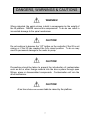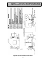
1
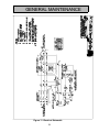
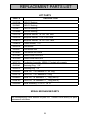
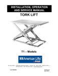
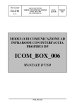
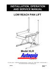
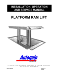
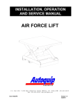
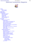
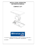
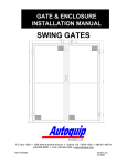
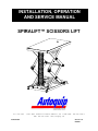
INSTALLATION, OPERATION
AND SERVICE MANUAL
SPIRALIFT™ SCISSORS LIFT
P.O. Box 1058
Item #830SL
• 1058 West Industrial Avenue Guthrie,
•
OK 73044-1058
•
FAX: 405-282-8105 • www.autoquip.com
405-282-5200 •
Version 1.0
07/2001
TABLE OF CONTENTS
Identification and Inspection
3
Dangers, Warnings, and Cautions
4
Label Identification
8
Specifications
11
Lift Blocking Instructions
12
Installation Instructions
14
Operating Instructions
18
Routine Maintenance
19
General Maintenance
21
Replacement Parts List
26
Troubleshooting Analysis
27
IMPORTANT
Please read and understand this manual prior to installation or operation of this lift.
Failure to do so could lead to property damage and/or serious personal injury. If any
questions arise, call a local representative or Autoquip Corporation at 1-888-811-9876
or 405-282-5200.
PLANNED MAINTENANCE PROGRAM
A local Autoquip representative provides a Planned Maintenance Program (PMP) for
this equipment using factory-trained personnel. Call a local representative or Autoquip
Corporation at 1-888-811-9876 or 405-282-5200 for more information.
2
IDENTIFICATION & INSPECTION
IDENTIFICATION
When ordering parts or requesting information or service on this lift, PLEASE REFER
TO THE MODEL AND SERIAL NUMBER. This information is on a nameplate attached
to the leg assembly. Replacement parts are available from a local Autoquip distributor.
INSPECTION
Immediately upon receipt of the lift, a visual inspection should be made to determine
that it has not been damaged in transit. Any damage found must be noted on the
delivery receipt. In addition to this preliminary inspection, the lift should be carefully
inspected for concealed damage. Any concealed damage found that was not noted on
the delivery receipt should be reported in writing to the delivering carrier within 48 hours.
The following is a checklist that will aid you in the inspection of this lift:
1. Examine entire unit for any signs of mishandling. Pay special attention to the drive
mechanism, limit switches, and pushbuttons.
2. Thoroughly examine all connections, making sure they have not vibrated loose
during transit, and inspect wiring for any signs of damage.
3. After installation, raise the lift and inspect the base frame, platform, scissors
assembly, and spiral mechanism connections.
3
DANGERS, WARNINGS & CAUTIONS
SAFETY ALERTS (Required Reading!)
The following SAFETY ALERTS are intended to create awareness of owners,
operators, and maintenance personnel of the potential safety hazards and the steps that
must be taken to avoid accidents. These same alerts are inserted throughout this
manual to identify specific hazards that may endanger uninformed personnel.
Identification of every conceivable hazardous situation is impossible. Therefore, all
personnel have the responsibility to diligently exercise safe practices whenever exposed
to this equipment.
____________________________________________________________
DANGER!
Identifies a hazardous situation that presents the imminent probability of
death or of severe personal injury!!
_____________________________________________________________
WARNING!
Identifies a hazardous situation that has the potential of causing death or
serious personal injury.
CAUTION!
Identifies a hazardous situation that could lead to the possibility of personal
injury of death, and/or may result in equipment damage.
_____________________________________________________________
4
DANGERS, WARNINGS & CAUTIONS
Read and understand this manual and all labels prior to operating or
servicing the scissors lift. All labels are provided in accordance with
ANSI Z535.4.
DANGER!
Do not work under lift without Maintenance Device! To avoid personal
injury, NEVER go under the lift platform until the load is removed and the
scissors mechanism is securely blocked in the open position. See "Lift
Blocking Instructions" section.
DANGER!
To avoid personal injury, stand clear of scissors mechanism while the lift is
in motion.
DANGER!
Do not install the lift in a pit unless it has a bevel toe guard or other
approved toe protection. A shear point can exist which can cause severe
injury to the foot.
DANGER!
HIGH VOLTAGE!! Disconnect and/or lock out the electrical supply to the
power unit prior to any maintenance being performed.
5
DANGERS, WARNINGS & CAUTIONS
DANGER!
Scissors lifts are designed individually for a specific load and application.
To avoid personal injury, do not change the load or application from the
original design.
WARNING!
NEVER stand, sit or ride on the lift!
WARNING!
All warning and information decals should be in place as outlined in the
“Label Identification” section. If decals are missing or damaged, they
should be replaced with new ones. Contact Autoquip for replacements.
WARNING!
Do not attempt to remove the drive mechanism or drive belt until the
maintenance locks securely support the empty lift. Failure to do so could
results in personal injury or death!
WARNING!
Lift platforms traveling below floor levels my create openings, and the
shape of the load and how the load is arranged on the lift may create a toe
hazard as the load passes the top edge of the pit. Both situations may
require guarding in accordance with Federal Regulations. Any such
guarding must be installed prior to operating the lift.
.
6
DANGERS, WARNINGS & CAUTIONS
WARNING!
When extended, the spiral column is held in compression by the weight of
the lift platform. NEVER remove this compression! To do so can result in
irreversible damage to the spiral mechanism.
CAUTION!
Do not continue to depress the “UP” button on the controller if the lift is not
raising or if the lift has reached the fully raised position. To do so may
result in permanent damage to the motor or pump.
CAUTION!
Precautions should be taken to prevent the introduction of contaminates
such as dirt or other foreign material into the drive system through open
fittings, pipes or disassembled components. Contamination will ruin the
drive mechanism.
CAUTION!
At no time should the scissor table be raised by the platform.
7
LABEL IDENTIFICATION
Figure 1 Label Placement
Spiralift™ Scissors Lift
Item No.
Qty
Description
Part No.
1
2
Caution – Familiarize Yourself With Operators Manual
36401487
2
4
Danger – Do Not Put Hands or Feet . . .
36430050
3
1
Autoquip Serial Number Nameplate
36401511
4
2
Capacity
36401586
5
1
Danger – Do Not Disassemble Motor & Gearbox
36405110
6
2
Warning – Never Apply Side Load to Spiral Column
36403890
8
LABEL IDENTIFICATION
Note: Labels shown here are not actual size.
Figure 2 Label 36401487
Figure 3 Label 36430050
Figure 4 Label 36401511
9
LABEL IDENTIFICATION
Figure 5 Label 36401586
Figure 6 Label 36405110
Figure 7 Label 36403890
10
SPECIFICATIONS
Model
Number
Capacity
(Pounds)
Travel
(In.)
Lowered
Height
(Inches)
Raised
Height
(Inches)
Max
End
Load
(lbs)
Max
Side
Load
(lbs)
Standard
Platform
& Base
Frame
(Inches)
Maximum
Allowable
Platform
Size
Stan.
Raise
Time
(sec)
Optional
Raise
Time
(sec)
Sh
Wt
36SL25
2,500
36
9 1/2
45 1/2
2500
2500
24 x 56
48 x 80
18
12
70
36SL40
4,000
36
9 1/2
45 1/2
3000
3000
24 x 56
48 x 80
18
12
72
36SL60
6,000
36
9 1/2
45 1/2
3000
3000
24 x 56
48 x 80
24
12
75
48SL25
2,500
48
10 1/4
58 1/4
2500
2500
24 x 72
48 x 104
24
16
77
48SL40
4,000
48
10 1/4
58 1/4
2500
2500
24 x 72
48 x 104
24
16
80
48SL60
6,000
48
10 1/4
58 1/4
2500
2500
24 x 72
48 x 104
32
16
82
LOAD CAPACITY
The load capacity rating is stamped on a metal plate attached to one side of the lift.
This figure is a net capacity rating for a lift furnished with the standard platform. Where
gravity roll-sections, special tops, etc, are installed on the lift after leaving the plant,
deduct the weight of these from the load rating to obtain the net capacity. Lifts should
not be overloaded beyond the established capacity as damage and/or personal
injury may result.
UNBALANCED LOADING
The stabilization provided is basically for balanced loads. If special attachments extend
beyond the length and/or width dimensions of the platform, the end and/or side load
capacity is reduced 2% for each one-inch extension from the center. If the load is
rolling onto the platform (in any but the fully-lowered position) the end and/or side load
capacity is reduced by a 50% impact factor (i.e., divide the rated end/side load by 1.50
to establish an available “axle” load).
11
LIFT BLOCKING INSTRUCTIONS
1. Remove all load from the platform. Never block the lift when loaded.
2. Raise the platform sufficiently for the base rollers to rollback past the flip-over
maintenance locks, located on the base frame of the lift.
3. Engage both maintenance locks by flipping them over (see Figure 8).
4. Lower the platform until the base rollers come into contact with and rest against the
maintenance locks. Always hold the “DOWN” switch a few seconds more until all
pressure is gone and the platform is supported entirely and safely by the
maintenance locks.
5. Always shut off the main electrical switch, when blocked, to prevent someone from
turning it on.
DANGER!
To avoid personal injury, NEVER go under the platform until the load is
removed and the lift is securely blocked in the open position.
6. To remove the maintenance locks, raise the platform by activating the “UP” switch to
provide sufficient clearance for the removal of the maintenance locks.
DANGER!
Maintenance locks that are bent, damaged, or non-functional must be
replaced immediately to avoid personal injury. Contact the Autoquip
Service Department for replacement parts and installation instructions.
12
LIFT BLOCKING INSTRUCTIONS
FLIP-OVER MAINTENANCE
LOCKS SHOWN IN PLACE ON
BOTH SIDES OF BASE FRAME
Figure 8 Maintenance Locks
13
INSTALLATION INSTRUCTIONS
FLOOR INSTALLATION
DANGER!
Do not work under the lift without the maintenance device! To avoid
personal injury, NEVER go under the lift platform until the load is removed
and the scissors mechanism is securely blocked in the open position. See
“Lift Blocking Instructions” section.
1. Make sure installation area is clean before starting.
2. If the permanent electrical work is not complete, some means of temporary lines with
an on-off device for the power supply should be set up for testing purposes.
3. Place the lift in the installation area.
CAUTION!
When moving the lift, do not attempt to pick it up by the platform; it is
hinged and could be damaged. Pick up the lift from under the base frame
ONLY using lifting eyes or a strap sling.
4. Remove the shipping straps (the lift is shipped in a slightly raised position for
checking rotation).
5. Check wiring connections to the motor for proper rotation of the spiral mechanism.
6. Make temporary electrical connections. Raise the lift just high enough to engage the
safety locks. Once the “UP” limit switch is functional, raise the lift to the top of its
travel. Make positioning adjustments and check for the proper height. If needed,
shim to the desired height. DO NOT “Spot” shim. Shim the full length of the base
frame. This will prevent the frame from sagging under an exceptionally heavy load.
14
INSTALLATION INSTRUCTIONS
CAUTION!
Over-travel of the spiral mechanism could cause permanent damage to the
mechanism. Ensure that the “UP” limit switch is operational before raising
the lift to a fully raised position.
7.
The base frame of the lift has pre-drilled holes for lagging the lift securely to the
floor. Mark the holes, drill, and install with anchors. Lifts with oversize platforms
have minimum pullout requirements of 2,000 lbs. for each anchor.
8.
Make permanent electrical connections and operate the lift through a few cycles.
9.
Apply all warning labels in the correct location. See “Label Identification” section.
10. Clean up any debris from the area. A clean installation makes a good impression
and creates a much safer environment.
PIT INSTALLATION -- MODELS WITH BEVEL TOE GUARDS
DANGER!
Do not install the lift in a pit unless it has a bevel toe guard or other
approved toe protection. A shear point can exist which can cause severe
injury to the foot.
1.
Check the pit dimensions. Length and width should be 2" minimum longer and
wider than the lift platform. Depth should include _” allowance for shims or grout.
2.
Check the chase entrance into the pit. The diameter should be 3". If the
permanent electrical work is not complete, some means of temporary lines with an
on-off device for the motor should be set up for testing purposes.
3.
Lower the lift into the pit and check for proper height. The lift should be solid and
flush with the pit angle framing. If needed, shim to the desired height. DO NOT
“spot” shim. Shim the full length of the base frame. This will prevent the frame
from sagging under an exceptionally heavy load.
15
INSTALLATION INSTRUCTIONS
CAUTION!
When moving the lift, do not attempt to pick it up by the platform; it is
hinged and could be damaged. Pick up the lift from under the base frame
ONLY using lifting eyes or a strap sling.
4.
Remove the shipping straps (the lift is shipped in a slightly raised position for
checking rotation).
5.
Check wiring connections to the motor for proper rotation of the spiral mechanism.
6.
Make temporary electrical connections. Raise and lower the lift to make
positioning adjustments and align the platform in the pit with a proper clearance of
3/4” minimum around the edges from the platform to the pit angle.
DANGER!
Do not work under lift without Maintenance Device! To avoid personal
injury, NEVER go under the lift platform until the load is removed and the
scissors mechanism is securely blocked in the open position. See "Lift
Blocking Instructions" section.
7.
The base frame of the lift has pre-drilled holes for lagging the lift securely to the
floor. Mark hoes, drill, and install with anchors. Lifts with oversize platforms have
minimum pull out requirements of 2,000 lbs. for each anchor.
8.
Make the permanent electrical connections and operate the lift through a few
cycles.
9.
Apply all warning labels in the correct location. See “Label Identification” section.
10. Clean up any debris from the area. A clean installation makes a good impression
and creates a much safer environment!
16
INSTALLATION INSTRUCTIONS
Figure 9 Top Plate Assembly & Limit Switch
17
OPERATING INSTRUCTIONS
It is mandatory that all authorized maintenance and installation personnel become
completely familiar with the contents of this manual before working on the Spiralift™.
The following instructions were written to ensure safe and reliable operation of the lift. If
the Spiralift™ is not maintained according to the instructions given in this manual, the
warranty may become void by Autoquip.
The Spiralift™ power unit is a very durable and dependable precision mechanism. It
will give many years of trouble-free service if taken care of properly. It should be
treated the same as any precision instrument.
The upward and downward movement of the platform must not be restricted during
operation of the Spiralift™ scissor table. The spiral mechanism is designed to “stack”
under compression. If this compressive force is not maintained, the spiral may
“unstack” and cause immediate and irreversible damage to the spiral mechanism.
WARNING!
When extended, the spiral column is held in compression by the weight of
the lift platform. NEVER remove this compression! To do so can result in
irreversible damage to the spiral mechanism.
When the “UP” button is pressed, the coil of the motor starter will close the line contact
permitting 3-phase electrical power to be applied to the motor. The rotating motor shaft
is mechanically coupled to a gear reducer. The gear reducer has an output shaft with a
belt drive system tied to the spiral mechanism. As the motor rotates, the spiral
mechanism turns and “builds” a spiral column that raises the lift platform from beneath
until the power is shut off by either releasing the “DOWN” button or until the lift makes
contact with the “UP” limit switch. .
Pressing the “DOWN” button will cause the reversing motor starter to engage and start
the motor. The gear reducer and belt drive system now turn the spiral mechanism in
the opposite direction, thereby “un-building” the spiral column causing the lift platform to
lower until the power is shut off by releasing the “DOWN” button or until the lift makes
contact with the “DOWN” limit switch.
WARNING!
NEVER stand, sit or ride on the lift!
18
ROUTINE MAINTENANCE
Normally scissors lifts will require very little maintenance. However, a routine
maintenance program could prevent costly replacement of parts and/or downtime.
WARNING!
To avoid personal injury, NEVER go under the lift platform or perform any
maintenance on the lift until the load is removed and the scissors
mechanism is securely blocked in the open position. See "Lift Blocking
Instructions" section.
MONTHLY INSPECTION
1. Lubricate the spiral mechanism (see recommendations in this section).
2. Check any unusual noise when it occurs. Determine the source and correct as
necessary.
3. Check the snap rings at all rollers, if not in place, and/or secure, replace or repair
immediately.
4. Check all rollers for signs of wear. Replace as necessary.
5. Do not grease roller or axles; they have lifetime-lubricated bearings.
6. Check all wiring for looseness or wear. Repair at once.
7. Check for metal particles or filings around the base of the spiral mechanism.
19
ROUTINE MAINTENANCE
LUBRICATION CHART – SPIRAL MECHANISM
Lubrication
Or Solvent
(Type/Specification)
Manufacturer
(see note)
Ep Grease
EP 2
Gear Oil
API – GL1
or
API – GL2
Mechanical parts cleaning
solvent
Various,
except paint
thinner
Equipment or
Component
(When supplied)
Pillow blocks, Zerk
fittings
Method of
Application
Use hand grease gun
Vertical and
horizontal bands
Squirt with no excess on
bands as they roll up to form
the column
Bearings, other
bearing surfaces
Squirt with no excess
Drive, synchronizing
chains
Brush or wipe on sparingly
Clean mechanical
parts only (not for
use on electrical
parts)
As required, wipe dry
**Industry approved equivalents may be used except where manufacturer specifies otherwise.
Failure to comply with the manufacturer’s specification could void the warranty.
20
GENERAL MAINTENANCE
CAUTION!
At no time should the scissor table be raised by the platform.
Item
Maintenance
Task
Corrective Action
Spiralift™ drive
chains
Spiralift™
gearbox
Check for excess
slack and alignment
Check the oil level
of the gearbox
3
Drive belts
4
Check condition
and tightness
Check lubrication of
the gears
Driving pinion of
the gearbox and
ring gear on the
Spiralift™
Vertical band and Check for rust or
horizontal band
accumulation of dirt
of the Spiralift™
on the bands
Retighten or realign;
re-lubricate.
Remove the top and
side oil plug; add oil in
the top opening until
oil starts to flow from
the side opening. Reinstall plugs.
Retighten or replace
as required.
Clean and re-lubricate
both gears.
1
2
5
Description
6
Inserting system
7
Vertical band
magazine
Check for loose
screws on the
vertical band
inserting system
and on the vertical
band retainer.
Make sure
magazine is
spinning freely with
no friction due to
dirt in the bearing.
O/C
D
M
S
X
X
X
X
X
X
Clean and wipe the
bands and spray gear
oil on the bands, with
no excess, as they roll
up into the column
structure.
Tighten if required.
Caution: All fasteners
are assembled with
“loctite”.
X
X
X
X
Clean and lubricate
magazine ball bearing
system.
X
X
Legend: O/C = On condition (when item becomes unserviceable; D = Daily; M = Monthly;
S = Semi-annually; A = Annually. If over one year, maintenance interval will be specified.
21
A
GENERAL MAINTENANCE
REPLACING THE SPIRAL MECHANISM
1.
Raise the scissors table three to four feet and block it securely (see “Lift Blocking
Instructions”).
2.
Remove the spiral mechanism by disabling the security switch and then
disconnecting the top plate from the scissors table. Allow the mechanism to unbuild back into the storage canister.
3.
Install the new motor on the base plate. Install the pulleys on the motor and the
gearbox drive shafts.
4.
Position the Spiralift™ on its base plate in the scissors lift table. Make sure that
the center of the Spiralift™ and center of the nesting are aligned to ensure the
Spiralift™ is plumb properly during its travel.
5.
Level the Spiralift™.
6.
Turn the Spiralift™ manually by inserting a _” diameter bar in the holes of the
head. Move the top plate two turns up.
7.
Install the “V” belts on the motor and gearbox pulleys
8.
Connect the motor to a power source and jog the control push buttons to check the
rotation of the Spiralift™.
9.
Manually lower the platform of the scissors lift table onto the Spiralift™ top plate
making sure it is properly inserted into the nesting.
10. Raise the platform two feet.
11. Carefully inspect the extended column of the Spiralift™ to ensure that the vertical
band is properly seated in the groove of the horizontal band throughout.
12. Run the Spiralift™ through several cycles making sure that to stay at least four
inches away from the upper and lower end of the travel of the Spiralift™. If it does
not run fully plumb, level the Spiralift™ and/or move the base plate in line with the
nesting.
22
GENERAL MAINTENANCE
13. Readjust the upper and lower limit switch. This will stop the electric motor. The
lifting unit has a mechanical stop at each end of the travel. This is done so the
Spiralift™ will not be driven out of the travel limits for which it was designed, thus
avoiding serous damage.
14. Enable the security switch on the scissors lift to detect the loss of contact between
the Spiralift™ to plate and the lift tabletop plate. This security switch will stop the
Spiralift™ until if the contact is lost (see Figure 9).
23
GENERAL MAINTENANCE
Figure 11 Electrical Schematic
24
REPLACEMENT PARTS LIST
LIFT PARTS
PART #
DESCRIPTION
20022158
14DU12 Bushing
20022851
18DU12 Bushing
20022877
18DU16 Bushing
20023966
24DU24 Bushing
24001018
MolyKote Washer, 7/8” id x 1/64” thick
24002016
MolyKote Washer, 1 1/8” x 1/64” thick
24008013
MolyKote Washer, 7/8” ID x 1/32” thick
24094518
Plastic Washer, 1 1/2”
34000018
Limit Switch
34000257
Limit Switch Arm
35103380
Foot Switch and Guard
35107980
Control Panel 230V/3PH
35107990
Control Panel 460V/3PH
36201730
Pushbutton Assembly, NEMA-4, Pendant with magnets
45400082
Retaining Ring, 1 1/8”
45400215
Retaining ring, .7/8”
52500253
Roller Pin, 1 1/8” diameter x 1 3/4” long
52502705
Clevis Pin, 1 1/8” diameter x 2” long
52504630
Roller Pin, 7/8” diameter x 1 _” long (36S15)
52504780
Clevis Pin, 7/8” diameter x 1 _” long (36S15)
52600269
Roller Assembly, 3” OD x 1 1/8” ID
SPIRAL MECHANISM PARTS
See accompanying GALA Manual for parts list. Contact GALA directly for parts
replacement assistance.
25
TROUBLESHOOTING ANALYSIS
DANGER!
To avoid personal injury, NEVER go under the lift platform until the load is
removed and the scissors mechanism is securely blocked in the open position.
See "Lift Blocking Instructions" section.
PROBLEM
Platform jams during downward
stroke. Stop the lift immediately
if it has not already stopped
automatically.
POSSIBLE CAUSE AND SOLUTION
• If the top plate of the column is still in its pocket
under the top platform and the vertical band is
still in the groove of the horizontal band, the lift
may be jogged up until the column bears the
weight of the table. Remove the load from the
platform and remove the source of the
obstruction. Carefully inspect the extended
column of the lift to ensure that the vertical band
is properly seated in the groove of the horizontal
band throughout. Lower and raise the table
once with no load.
• The top plate of the column has come out of the
pocket of the top platform and the column has
rotated so that the top plate is no longer aligned
with the pocket, but the vertical band is properly
seated in the groove of the horizontal band.
Block the platform in its position and verify that
the platform won’t move. Remove the load.
Rotate the column from the top plate, by hand,
maintaining a downward pressure until the top
plate is aligned with the pocket on the underside
of the platform. It is advisable to use some
weight (50 pounds) over the top of the column to
perform this operation until it is brought close to
the top platform. Jog the lift drive upward until
the top plate enters the pocket and bears the
weight of the load. Proceed with the corrective
measures described above.
26
TROUBLESHOOTING ANALYSIS
PROBLEM
POSSIBLE CAUSE AND SOLUTION
Platform jams during downward
stroke. Stop the lift immediately if
it has not already stopped
automatically (continued from
previous page).
• The column has lost its integrity (i.e., the
vertical band has come out of the grove in the
horizontal band.) Block the platform in its
position. Remove the load. Feed the two
bands back into their respective storage
position by rotating the head of the column. If
this is difficult, remove the retaining screws at
the top end of the vertical band and then feed
the two bands back down individually. When
the horizontal band and the head assembly are
at the bottom and the vertical band is in the
magazine, re-attach the vertical band to the
head assembly and reinsert the retaining
screws. Rotate the column assembly up, by
hand, by rotating the top plate slowly. Proceed
with the corrective measures described above.
One of the driving belts on the
drive unit is broken.
• If at any time one of the driving belts breaks
loose, the platform movement will stop
automatically. A proximity switch senses the
broken belt and the platform will not move until
this belt is replaced. Block the platform in its
position. Remove the load. Verify that the
platform won’t move. Remove the belt guard
and replace both belts. If the column has been
lowered away from the top platform, re-insert
the top plate of the column into its pocket
according to previous steps described.
27