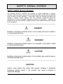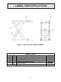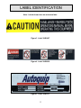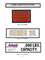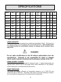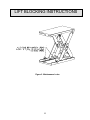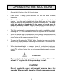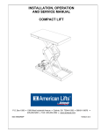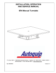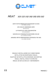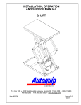
1
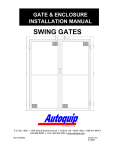
INSTALLATION, OPERATION AND SERVICE MANUAL SERIES 35 “ROVER” 12VDC PORTABLE LIFT P.O. Box 1058 1058 West Industrial Avenue Guthrie, OK 73044-1058 405-282-5200 FAX: 405-282-8105 www.autoquip.com Item #830SRV Version 2.0 06/2011 TABLE OF CONTENTS Identification and Inspection 3 Responsibility of Users/Owners 4 Safety Signal Words 5 Safety Practices 6 Label Identification 9 Specifications 13 Lift Blocking Instructions 14 Installation Instructions 17 Operating Instructions 22 Routine Maintenance 23 General Maintenance 25 Replacement Parts List 35 Troubleshooting Analysis 37 Warranty 41 IMPORTANT Please read and understand this manual prior to installation or operation of this lift. Failure to do so could lead to property damage and/or serious personal injury. If any questions arise, call a local representative or Autoquip Corporation at 1-888-811-9876 or 405-282-5200. PLANNED MAINTENANCE PROGRAM A local Autoquip representative provides a Planned Maintenance Program (PMP) for this equipment using factory-trained personnel. Call a local representative or Autoquip Corporation at 1-888-811-9876 or 405-282-5200 for more information. 2 IDENTIFICATION & INSPECTION IDENTIFICATION When ordering parts or requesting information or service on this lift, PLEASE REFER TO THE MODEL AND SERIAL NUMBER. This information is on a nameplate attached to the leg assembly. Replacement parts are available from a local Autoquip distributor. INSPECTION Immediately upon receipt of the lift, a visual inspection should be made to determine that it has not been damaged in transit. Any damage found must be noted on the delivery receipt. In addition to this preliminary inspection, the lift should be carefully inspected for concealed damage. Any concealed damage found that was not noted on the delivery receipt should be reported in writing to the delivering carrier within 48 hours. The following is a checklist that will aid you in the inspection of this lift: 1. Examine entire unit for any signs of mishandling. Pay special attention to the power unit and pushbuttons. 2. Thoroughly examine all connections, making sure they have not vibrated loose during transit, and inspect wiring for any signs of damage. 3. After installation, raise the lift and inspect the base frame, platform, scissors assembly, and cylinder plumbing connections. 3 RESPONSIBILTY OF OWNERS/USERS DEFLECTION It is the responsibility of the user/purchaser to advise the manufacturer where deflection may be critical to the application. INSPECTION & MAINTENANCE The lift shall be inspected & maintained in proper working order in accordance with Autoquip’s operating/maintenance (O&M) manual and with other applicable safe operating practices. REMOVAL FROM SERVICE Any lift not in safe operating condition such as, but not limited to, excessive leakage, missing rollers, pins, or fasteners, any bent or cracked structural members, cut or frayed electric, hydraulic, or pneumatic lines, damaged or malfunctioning controls or safety devices, etc. shall be removed from service until it is repaired to the original manufacturer’s standards. REPAIRS All repairs shall be made by qualified personnel in conformance with Autoquip’s instructions. OPERATORS Only trained personnel and authorized personnel shall be permitted to operate the lift. BEFORE OPERATION Before using the lift, the operator shall have: Read and/or had explained, and understood, the manufacturer’s operating instructions and safety rules. Inspected the lift for proper operation and condition. Any suspect item shall be carefully examined and a determination made by a qualified person as to whether it constitutes a hazard. All items not in conformance with Autoquip’s specification shall be corrected before further use of the lift. DURING OPERATION The lift shall only be used in accordance with Autoquip’s O&M manual. Do not overload the lift. Ensure that all safety devices are operational and in place. MODIFICATIONS OR ALTERATIONS Modifications or alterations to industrial lifting equipment shall be made only with written permission of Autoquip. Autoquip does not foresee and does not anticipate unauthorized modifications, and these changes or alterations are grounds for voiding all warranties. 4 SAFETY SIGNAL WORDS SAFETY ALERTS (Required Reading!) The following SAFETY ALERTS are intended to create awareness of owners, operators, and maintenance personnel of the potential safety hazards and the steps that must be taken to avoid accidents. These same alerts are inserted throughout this manual to identify specific hazards that may endanger uninformed personnel. Identification of every conceivable hazardous situation is impossible. Therefore, all personnel have the responsibility to diligently exercise safe practices whenever exposed to this equipment. ____________________________________________________________ DANGER! Identifies a hazardous situation which, if not avoided, will result in death or or severe personal injury. _____________________________________________________________ WARNING! Identifies a hazardous situation which, if not avoided, could result in death or serious personal injury. CAUTION! Identifies a hazardous situation which, if not avoided, may result in minor or moderate personal injury. _____________________________________________________________ CAUTION! Caution used without the safety alert symbol indicates a potentially hazardous situation which, if not avoided, may result in property or equipment damage. ____________________________________________________________ 5 SAFETY PRACTICES Read and understand this manual and all labels prior to operating or servicing the scissors lift. All labels are provided in accordance with ANSI Z535.4. DANGER! Do not work under lift without Maintenance Device! To avoid personal injury, NEVER go under the lift platform until the load is removed and the scissors mechanism is securely blocked in the open position. See "Lift Blocking Instructions" section. DANGER! To avoid personal injury, stand clear of scissors mechanism while the lift is in motion. DANGER! HIGH VOLTAGE!! Disconnect and/or lock out the electrical supply to the power unit prior to any maintenance being performed. DANGER! Scissors lifts are designed individually for a specific load and application. To avoid personal injury, do not change the load or application from the original design. 6 SAFETY PRACTICES WARNING! NEVER stand, sit or ride on the lift! WARNING! All warning and information decals should be in place as outlined in the “Label Identification” section. If decals are missing or damaged, they should be replaced with new ones. Contact Autoquip for replacements. WARNING! Do not attempt to remove the velocity fuse until the maintenance block securely supports the lift and all hydraulic pressure has been removed from the lifting cylinders and hydraulic hoses. Failure to do so could results in personal injury or death! WARNING! To avoid injury, use the floor lock when the unit is in use. Failure to use the floor lock may cause the unit to roll when it is in use. CAUTION! Do not continue to depress the “UP” button on the controller if the lift is not raising or if the lift has reached the fully raised position. To do so may result in permanent damage to the motor or pump. 7 SAFETY PRACTICES CAUTION! Never run the pump for more than a couple of seconds without pumping oil. This applies to low oil conditions, improper motor rotation, running the pump against the relief pressure after the lift is fully raised against the physical stops, running overloaded beyond capacity, or running at reduced speed because of pinched or obstructed hydraulic lines. CAUTION! Do not operate the power unit on relief for more than a few seconds. When on relief, the valve will make a squealing sound. CAUTION! Precautions should be taken to prevent the introduction of contaminates such as dirt or other foreign material into the system through open fittings, pipes or disassembled components. Contamination will ruin the hydraulic system. CAUTION! Use only approved oils in the lift. See “Specifications” section. 8 LABEL IDENTIFICATION Figure 1 Label Placement - Oversized Platform Series 35 Rover Item No. 1 2 3 4 5 6 Qty 2 4 1 1 2 2 Description Caution – Familiarize Yourself With Operators Manual Danger – Do Not Put Hands or Feet . . . Autoquip Serial Number Nameplate Fill with Recommended Oils Only Series 35 Label Capacity 9 Part No. 36401487 36430050 36401511 36400661 36402980 36401586 LABEL IDENTIFICATION Figure 2 Label Placement - Standard Platform Series 35 Rover Item No. 1 2 3 4 5 6 Qty 2 2 1 1 2 2 Description Caution – Familiarize Yourself With Operators Manual Danger – Do Not Put Hands or Feet . . . Autoquip Serial Number Nameplate Fill with Recommended Oils Only Series 35 Label Capacity 10 Part No. 36401487 36430050 36401511 36400661 36402980 36401586 LABEL IDENTIFICATION Note: Labels shown here are not actual size. Figure 3 Label 36401487 Figure 4 Label 36430050 Figure 5 Label 36401511 11 LABEL IDENTIFICATION Figure 6 Label 36400661 Figure 7 Label 36402980 Figure 8 Label 36401586 12 SPECIFICATIONS Series 35 Model Capacity (lbs) Travel (In.) Lowered Height (Inches) Raised Height (Inches) Max End Load (lbs) Max Side Load (lbs) Standard Platform (Inches) Raise Time (sec) No of Cyl Ship Wt (lbs) 24SRV25 2500 24 14 38 2500 1500 24 x 36 8* 1 910 24SRV40 4000 24 14 38 3000 1500 24 x 36 11* 1 950 24SRV60 6000 24 14 38 3500 1500 24 x 36 16* 2 1000 36SRV25 2500 36 14 50 2500 1500 24 x 48 12* 1 1000 36SRV40 4000 36 14 50 3000 1500 24 x 48 17* 1 1050 36SRV60 6000 36 14 50 3500 1500 24 x 48 25* 2 1100 48SRV25 2500 48 14 62 2500 1500 24 x 64 16* 1 1200 48SRV40 4000 48 14 62 3000 1500 24 x 64 22* 1 1250 48SRV60 6000 48 14 62 3500 1500 24 x 64 33* 2 1300 * Varies depending on amp draw in battery LOAD CAPACITY The load capacity rating is stamped on a metal plate attached to the lift. This figure is a net capacity rating for a lift furnished with the standard platform. Lifts should not be overloaded beyond the established capacity as damage and/or personal injury may result. DANGER! Do not make modifications to the lift without authorization from the manufacturer. Autoquip is not responsible for injury or damage which results from the unauthorized & unforeseen misuse of the lift. UNBALANCED LOADING The stabilization provided is basically for balanced loads. If special attachments are required which extend beyond the length and/or width dimensions of the platform, contact Autoquip for a recommended & safe solution. PUMP PRESSURE The pump can operate efficiently at intermittent pressures up to 3200 PSI and continuous duty to 2500 PSI. The safety relief valve in the pump assembly is factoryset to stay within the parameters of the pump and lift requirements. 13 LIFT BLOCKING INSTRUCTIONS WARNING ! Only authorized personnel should perform inspection or maintenance and service procedures. Unauthorized personnel attempting these procedures do so at the risk of personal injury or death. DANGER ! Failure to properly adhere to lift blocking procedures is to risk the sudden and uncontrolled descent of the lift during maintenance or inspection. A falling lift can cause severe injury or death. This procedure describes the only factory-approved method of working under a lift. Follow these instructions EVERY time you plan to reach or crawl beneath the lift to perform service or maintenance – no matter how momentary that might be. If the factory-provided maintenance devices are damaged or missing, stop immediately and consult the factory for assistance. The manufacturer is not liable for your failure to use the approved maintenance devices and procedures that have been provided. 1. All load must be removed from the lift prior to engaging the maintenance devices. These devices are designed to support an unloaded lift only. Failure to remove the load from the lift prior to blocking could cause the failure of the maintenance devices and allow the lift to fall unexpectedly. This can result in personal injury or death, or permanent damage to the maintenance devices and/or the lift. 2. Raise the lift to its fully raised position. If you do not, the maintenance devices may not be able to be placed properly in their designed blocking position. 3. Locate both hinged maintenance locks permanently welded outside the base frame on the roller end of the lift base legs. Both locks must be flipped over and resting inside the base frame and thus in the roller path of the lift (See Figure 9). 4. Lower the lift platform until the leg rollers make contact with both maintenance locks. Re-check to ensure that both devices are fully and properly engaged with the leg rollers. If both left and right maintenance locks are not fully engaged the lift could fall unexpectedly, resulting in permanent damage to the devices or the lift. 14 LIFT BLOCKING INSTRUCTIONS Figure 9 Maintenance Locks 15 LIFT BLOCKING INSTRUCTIONS DANGER ! If for any reason you are unable to lower the lift completely onto the maintenance device(s), stop immediately and consult the factory. Failure to properly use the factory approved maintenance device(s) could result in severe injury or death. 5. Once the maintenance devices are properly and securely engaged, continue to press the down button, valve or switch for an additional 5-10 seconds to relieve all pressure in the hydraulic system (it could take longer in a pneumatic system). WARNING ! Failure to relieve operating system pressure could result in the sudden and unexpected release of high pressure fluids (or air) during maintenance and/or repair of the lift and result in severe injury or death. 6. Follow OSHA electrical lock-out/tag-out procedures. Disconnect and tag all electrical and/or other power sources to prevent an unplanned or unexpected actuation of the lift. 7. Once inspection or work is complete, reverse the performance of the steps above to raise the lift off the maintenance devices and flip the devices back into their designated storage positions outside the base frame. DANGER ! HIGH VOLTAGE!! – Disconnect and/or lock out the electrical supply to the power unit per OSHA regulations prior to any installation or maintenance being performed. 16 INSTALLATION INSTRUCTIONS OIL The Rover is shipped with oil in the power unit. There is no need to fill it. STANDARD DC UNIT WARNING! Read and understand all of the instructions carefully before proceeding with the installation process. 1. The area where the Rover is to be used must be level, solid, and smooth. The unit should roll around freely without obstruction. DANGER! To avoid personal injury, NEVER use the unit in or around water or where flammable gasses may be present. 2. Remove the material the lift was shipped in. Remove the banding and the pallet from under the unit. 3. Connect the red positive battery cable. It may be necessary to charge the battery before the lift can be used. If the unit was purchased with the optional battery charger, it may be placed next to the battery. 4. Test the operation of the lift by pressing the “UP” button. Then push the “DOWN” button to lower the platform. If the lift does not work, see the “Troubleshooting” section in this manual. WARNING! All warning and information decals should be in place as outlined in the “Label Identification” section. If decals are missing or damaged, they should be replaced with new ones. Contact Autoquip for replacements. 17 INSTALLATION INSTRUCTIONS OPTIONAL 115/60 AC UNIT WARNING! Read and understand all of the instructions carefully before proceeding with the installation process. 1. The area where the Rover is to be used must be level, solid, and smooth. The unit should roll around freely without obstruction. DANGER! To avoid personal injury, NEVER use the unit in or around water or where flammable gasses may be present. 2. Remove the material the lift was shipped in. Remove the banding and the pallet from under the unit. 3. Plug the power cord into a suitable 20 amp grounded 115/60 receptacle. 4. Test the operation of the lift by pressing the “UP” button. Then push the “DOWN” button to lower the platform. If the lift does not work, see the “Troubleshooting” section in this manual. WARNING! All warning and information decals should be in place as outlined in the “Label Identification” section. If decals are missing or damaged, they should be replaced with new ones. Contact Autoquip for replacements. 18 INSTALLATION INSTRUCTIONS OPTIONAL AIR POWER UNIT UNIT WARNING! Read and understand all of the instructions carefully before proceeding with the installation process. 1. The area where the Rover is to be used must be level, solid, and smooth. The unit should roll around freely without obstruction. DANGER! To avoid personal injury, NEVER use the unit in or around water or where flammable gasses may be present. 2. Remove the material the lift was shipped in. Remove the banding and the pallet from under the unit. 3. Connect the power unit to the air supply. Make sure that the minimum working pressure is 80 psi @ 110 cfm. 4. Test the operation of the lift by moving the lever in the “UP” position. Then move the lever to the “DOWN” position to lower the platform. If the lift does not work, see the “Troubleshooting” section in this manual. WARNING! All warning and information decals should be in place as outlined in the “Label Identification” section. If decals are missing or damaged, they should be replaced with new ones. Contact Autoquip for replacements. 19 INSTALLATION INSTRUCTIONS PROCEDURE FOR A LIFT ORDERED WITH AN ACCORDION SKIRT 1. Position the platform in the raised position. Install the maintenance locks (see “Lift Blocking Instructions” section). Position the accordion with the weight rod pocket at the bottom and the mounting collar at the top. The breathable material when provided must be positioned at the top of the skirt with the mounting collar. 2. Slip the skirt over the end of the platform. Turn the skirt as required to slide over the other end of the platform and leg assembly. The skirt should be in position under the platform while enveloping the base assembly. 3. See the drawing below and select the correct mounting configuration (Figure 1, 2, or 3 from the drawing). Figure #1: Mounting an Accordion Skirt Onto the Platform Side Raise one side of the skirt along with a skirt -mounting bar (1/8” x 1”) to (1) side of the platform. When possible, center the skirt-mounting collar and skirtmounting bar (1/8” x 1”) on the platform side. Align the pre-drilled holes in the side of the platform with the skirt-mounting bar holes and punch holes in the skirtmounting collar. Push a nylon drive rivet through each hole in the skirt-mounting bar. Hammer the aluminum pin into the rivet until flush with the rivet head. Repeat mounting process for the remaining sides of the accordion skirt. Figure #2: Mounting an Accordion Skirt Underneath the Platform Raise one side of the skirt along with a skirt-mounting bar (1/8" x 1") to the underside of the platform skirt support bar. When possible, center the skirt mounting collar and the skirt-mounting bar (1/8” x 1”) on the platform support bar. Align the pre-drilled holes in the skirt support bar (picture frame) with the skirt mounting bar holes and punch holes in the skirt-mounting collar. Push a nylon drive rivet through each hole in the skirt-mounting bar. Hammer the aluminum pin into the rivet until flush with the rivet head. Repeat mounting process for the remaining sides of the accordion skirt. Figure #3: Mounting an Accordion Skirt Onto the Bevel Toe Guard Raise one side of the skirt along with a skirt-mounting bar (1/8” x 1”) to the side of the bevel toe guard. When possible, center the skirt mounting collar and the skirt-mounting bar (1/8” x1”) on the platform bevel toe guard. Align the pre-drilled holes in the bevel toe guard with the skirt-mounting bar holes and punch holes in the skirt-mounting collar. Push a nylon drive rivet through each hole in the skirtmounting bar. Hammer the aluminum pin into the rivet until flush with the rivet head. Repeat mounting process for the remaining sides of the accordion skirt. 4. Install weight rods into the weight rod pockets at the bottom of the accordion skirt. Install the spring tempered wire rods into the pocket of black convolutions. 20 INSTALLATION INSTRUCTIONS Figure 10 Skirt Installation 21 OPERATING INSTRUCTIONS 1. Operate this lift only on a firm, flat & level surface. 2. Place the lift in loading position and lock the floor lock when not being transported. 3. Scissors lifts have maximum lifting capacity ratings (See the “Specifications” section). The safety relief valve has been factory set to open at a point slightly above the rated load and allows the oil to bypass into the reservoir. The safety relief valve should not be adjusted for any reason as it could cause the motor to prematurely burn out. Applying loads exceeding the rated capacity of the lift may result in excessive wear and damage to the lift. 4. This lift is furnished with a constant pressure foot switch or pushbutton controls. Actuating the "UP" button will cause oil to enter the cylinders and the lift will rise. 5. When the desired height or upward travel of the platform is attained, removing the operator’s hand from the switch deactivates the “UP” circuit button. The oil stops flowing and the upward movement will stop. 6. To lower the lift, activate the "DOWN" button. Opening the down control valve allows the oil in the cylinders to flow through the down valve at a controlled rate and return oil to the reservoir. 7. When the desired height or downward travel of the platform is attained, removing the operator’s foot or hand from the switch deactivates the “DOWN” circuit. The oil stops flowing from the cylinders and the downward movement will stop. CAUTION ! Personnel should always maintain a safe operating distance of at least 36” any time the lift is operated up or down. CAUTION! Do not operate the power unit on relief for more than a few seconds. When on relief, the valve will make a squealing sound. 22 ROUTINE MAINTENANCE WARNING! Before installing lift, read & follow the recommended safety practices in the Safety Practices section. Failure to follow these safety practices could result in death or serious injury. Normally scissors lifts will require very little maintenance. However, a routine maintenance program could prevent costly replacement of parts and/or downtime. WARNING! Do not work under lift without Maintenance Device! To avoid personal injury, NEVER go under the lift platform until the load is removed and the scissors mechanism is securely blocked in the open position and the appropriate OSHA lock-out/tag-out procedure is followed . See "Lift Blocking Instructions" section. MONTHLY INSPECTION 1. Check oil level and add oil as necessary (see recommendations this section). 2. Check for any visible leaks. Correct as necessary. 3. Check any unusual noise when it occurs, take any necessary corrective action. 4. Check snap rings at all rollers. If missing or loose, replace/repair at once. 5. Check all rollers for signs of wear. Replace as necessary. 6. Do not grease roller or axles; they have lifetime-lubricated bearings. 7. Check all wiring for looseness or wear. Repair at once. 8. Check the set screws which capture cylinder trunnion pins. Tighten as needed. OIL REQUIREMENTS Change oil yearly, or more frequently if it darkens materially or feels gummy or gritty. Do not use hydraulic-jack oil, hydraulic fluids, brake fluids, or automatic transmission fluid. 23 ROUTINE MAINTENANCE Oil Viscosity Recommendations Environment Recommended Oil (Ambient Temperatures) Indoor location, variable 10W30 or 10W40 temperatures (30 - 100° F) Multiviscosity motor oil Indoor location, consistent SAE-20W motor oil Temperatures (70° F) Outdoor location, (-10 - 100° F) SAE 5W30 Multiviscosity motor oil Cold-storage warehouse 5W30 Multiviscosity (10 - 40° F) motor oil Freezer (-40° F to 0° F) Consult Factory OIL CAPACITY Standard polyethylene tank capacity is approximately five quarts. POWER UNIT Battery (DC) Standard 12 volt battery operated Internal power unit Electric (AC) 115/60 single phase ¾ hp “super-torque” motor Full load AMP draw - 16.6 Fuse size – 45 AMPs Circuit breaker – 40 AMPs Pneumatic Internal air power unit Minimum working pressure 80 psi @ 110 cfm 24 GENERAL MAINTENANCE WARNING! Before installing lift, read & follow the recommended safety practices in the Safety Practices section. Failure to follow these safety practices could result in death or serious injury. CYLINDER REMOVAL AND REPACKING 1. Raise the lift to its full height and block securely. See “Lift Blocking Instructions”. 2. Cut off the electricity to the power unit (lock out-tag out). 3. Disconnect the cylinder hose at the power unit end and insert it into the oil-fill hole of reservoir. 4. Loosen the setscrew in the cylinder upper clevis. 5. Remove the cylinder pin from the upper clevis. 6. Lift the cylinder out of the leg assembly. 7. Push the piston rod into the cylinder to eject as much oil as possible into a container. 8. Insert a Spanner wrench and turn the upper bearing assembly clockwise until the tip of the retainer appears in the slot. Place a small screwdriver under the retainer and turn it until the retainer is completely removed. 9. Be sure the hose port is open to allow air into the cylinder. Pull the piston rod out to remove the upper bearing. 10. After all of the internal components have been removed, use a bright light to inspect the inner walls of the barrel. Use a cylinder hone to remove any apparent nicks or scratches. Clean and flush the barrel after honing. 11. Remove the piston head nut from the rod. The upper clevis and pin may be used to prevent rotation of the rod while loosening. Remove the old piston. 12. Inspect the groove for nicks or scratches that could affect the seal or barrel walls; remove as necessary. 13. Install the new piston, seals, and rod wiper. 25 GENERAL MAINTENANCE 14. Check the piston head nut for tightness and torque to 600-650 ft. lbs on 3 ½” bore cylinders or 850-950 ft. lbs. on 4” bore cylinders. The upper clevis and pin may be used to prevent the rotation of the rod while tightening. 15. Liberally lubricate the piston and seal with CLEAN grease or oil. 16. Reinsert the piston into the barrel, taking care not to pinch or nick the new seal. 17. Slip the bearing assembly into place and align the retainer hole with the slot in the barrel. 18. Turn the bearing with the Spanner wrench until the retainer is reinserted completely. 19. Pull up the rod and reinstall the upper clevis pin and setscrew. 20. Reconnect the cylinder hose. 21. Check that the lag bolts are secure after checking all pins and other mechanical and hydraulic components. 22. Restore the oil level (see oil recommendations in the “Routine Maintenance” section. 23. Turn on the electrical power and press the “UP” button. It may take a few seconds to fill the empty cylinders. Raise the tilter approximately one inch and remove the maintenance block. 24. Lower the lift completely and hold the “DOWN” button for 60 seconds to allow air in the cylinders to bleed back into the tank. 25. Raise the lift to 25 – 50% of its full travel, then lower fully holding the “DOWN” button for an additional 60 seconds. Repeat this step 8 – 10 times. 26. Check the oil level (see oil requirements). 27. Clean the oil fill breather cap. PIPE THREAD SEALANT Loctite PST #567 pipe thread sealant or equivalent is recommended. Do not use Teflon tape. Tape fragments can cause malfunctioning of the hydraulic system. 26 GENERAL MAINTENANCE VELOCITY FUSE REPLACEMENT DANGER! Do not attempt to remove the velocity fuse until the lift is securely supported with the maintenance locking devices and all hydraulic pressure has been removed from the lifting cylinders and hydraulic hoses. Failure to follow these instructions could result in personal injury or death! Never attempt to take a velocity fuse apart and repair it. These are precision devices that are factory assembled under exacting conditions. Velocity fuses should always be replaced. 1. The arrow on the exterior surface of the velocity fuse shows the direction of the restriction to the oil flow. The arrow should always point away from the cylinder. 2. Do not use Teflon tape on the threaded connections of a velocity fuse. Tape fragments can cause malfunctioning of the fuse. 3. Check all fitting connections for hydraulic leaks and tighten as necessary. HOSE ORIENTATION To prevent damage to the cylinder hose and possible failure of lift, it is necessary to establish a correct hose shape and pattern of movement as follows: 1. Raise the lift to its full height and block securely. See “Lift Blocking Instructions”. 2. Install one end of the new hose to the cylinder elbow fitting. 3. Since the hose is fixed at both ends, it is possible to put a twist in the hose that will allow it to describe the same pattern each time the lift is operated. This twist will allow the hose to travel about half way between the cylinder on the right side and the inner leg on the right side. 4. Lower the lift carefully and check to see that the hose is free and clear of the cylinder and the inner leg assembly. If not, twist the hose in the direction necessary to clear it of any obstruction and then lock the swivel fitting securely. 27 M 28 SUCTION LINE FILTER P.F. RESERVOIR RELIEF VALVE CHECK VALVE DOWN SOL. VALVE PUMP ASSEMBLY PROVIDES THE FUNCTIONS OF CHECK, RELIEF, AND SOLENOID LOWERING VALVE. DOWN FLOW CONTROL VELOCITY FUSE LIFT CYLINDER GENERAL MAINTENANCE Figure 11 Hydraulic Schematic GENERAL MAINTENANCE WIRING AUTOQUIP "SUPER TORQUE' MOTORS Because Autoquip "Super-Torque" motors actually deliver substantially more horsepower than their nameplate rating, they must always be wired for heavier currentdraw than standard motors of the same nameplate rating. However, because of the "Super-Torque" motor’s starting efficiency and superior running characteristics, circuit components do not have to be as large as for standard motors of equal delivered horsepower. The following chart should be observed in connecting these motors to power sources, remembering that, where 115-Volt operation is contemplated, the current-draw is too heavy for plugging into ordinary lighting circuits. Heavy wire must be used all the way to the power-source. HP and Source ½ HP / 115 V/60 CY/1 PH Fuse Size 45 A Circuit Breaker 40 A ¾ HP / 115 V/60 CY/1 PH 45 A 40 A ¾ HP / 230 V/60 CY/1 PH 25 A 20 A 1½ HP / 208-230 V/60 CY/3 PH 15 A 10 A 1½ HP / 460 V/60 CY/ 3 PH 7.5 A 5A NOTE: For larger horsepower motors, consult factory. MOTOR CONNECTION DIAGRAMS 29 PUMP / MOTOR ASSEMBLY DOWN SOLENOID M UP DOWN + - DC MOTOR GENERAL MAINTENANCE Figure 12 Electric Schematic; 12VDC 30 31 90 P.S.I 110 C.F.M (MIN. FREE AIR) REQUIRED FILTERED AIR SUPPLY Figure 13 Air Schematic EXHAUST TO ATMOSPHERE REGULATOR (BY OTHERS). P A B AIR CONTROL VALVE (GENERIC VALVE LUBRICATOR AIR HOSE AIR LIMIT VALVE (WHEN USED) AIR HOSE. SUCTION LINE FILTER MOTOR PUMP MUFFLER DOWN VALVE AIR OPERATED AIR / HYDRAULIC SCHEMATIC RESERVOIR RELIEF VALVE CHECK VALVE HYDRAULIC VALVE PROVIDES COMPLETE, THE FUNCTION OF CHECK VALVE, RELIEF VALVE, AIR OPERATED DOWN VALVE. PRESSURE HOSE. (BY OTHERS) DOWN FLOW CONTROL VALVE QUANTITY OF CYLINDER / RAMS AND VELOCITY FUSES DEPENDS ON THE MODEL OF LIFT USED. VELOCITY FUSE LIFTING CYLINDER OR RAM GENERAL MAINTENANCE Figure 14 Electric Schematic; 115V/1Ph 32 OPTIONAL FOOTSWITCH W/ GUARD (NEMA 1) SHIPPED LOOSE WHEN ORDERED. TO BE INSTALLED AND WIRED (BY OTHERS) 3. TYPICAL PILOT CONTROLS ONLY ELECTRICAL SCHEMATIC TRANSFORMER PRIMARY CONNECTION DIAGRAMS ARE LOCATED ON INSIDE OF FRONT COVER. (RED) (GRN) L1 (WHEN USED) (BLACK) (GRN.) (WHITE) (BLACK) "UP" LIMIT SWITCH (XF) 2. PUSHBUTTON (WHITE) 2.5 AMP FUSE MOTOR STARTER, CONTROL TRANSFORMER, OVERLOADS, AND FUSES TO BE MOUNTED IN NEMA 1 ENCLOSURE, PRE-WIRED, AND MOUNTED TO POWER UNIT. L2 1. FOOT SWITCH SEE NOTE #3 (GRN) 115 VOLT 60 CYCLE 1 PHASE L1 FUSED DISCONNECT (BY OTHERS) TRANSFORMER (ORANGE) T3 L3 T1 T2 O.L. L2 DN. SOL. (BLUE) O.L. RELAY CONTACT MOTOR STARTER L2 CONTACTOR COIL 24V. 115V. L2 L1 MOTOR STARTER CONTACTS L1 CONNECTION No. ON DEVICE. STANDARD PUSHBUTTON COLOR CODE ELECTRICAL LEAD (PIG TAIL) IDENTIFICATIONS BLACK - MOTOR WHITE - MOTOR ORANGE - DOWN SOLENOID RED - DOWN SOLENOID GREEN - EQUIPMENT GROUND (WHITE) (BLACK) MOTOR: 3/4 HORSEPOWER 115 VOLT 60 CYCLE 1 PHASE GENERAL MAINTENANCE GENERAL MAINTENANCE Figure 15 Guarded Footswitch Assembly 33 GENERAL MAINTENANCE Figure 16 Limit Switch Wiring Diagram 34 REPLACEMENT PARTS LIST PART # DESCRIPTION 20046320 20046314 20079430 22688154 MECHANICAL Swivel Caster with 5” Dia. Wheel Rigid Caster with 5” Dia. Wheel Floor Lock (Must have mounting bracket on base) Cylinder Pin Set Screw 24002016 24094518 45400082 MolyKote Washer, 1 1/8” x 1/64” thick Plastic Washer, 1 1/2” Retaining Ring, 1 1/8” 52500253 52502705 52503141 52600269 60950003 Roller Pin, 1 1/8” diameter x 1 3/4” long Clevis Pin, 1 1/8” diameter x 2” long Cylinder Pin, 1 1/8” diameter x 6 ¼” long Roller Assembly, 3” OD x 1 1/8” ID “T” Handle Assembly 37200242 37200220 37200320 POWER UNITS - DC Internal 12V DC Power Unit Complete (For 36” & 48” Travel) With Pendent Pushbutton Internal 12V DC Power Unit Complete (For 36” & 48” Travel) With Foot Switch Battery Charger, 115VAC to 12V DC Battery, 12V DC Battery ‘Hold Down’ Cross Bar 37200330 37200310 36202150 35103380 30400310 37200219 35000579 Bolt, for Cross Bar Battery Cable, Red Pendent Pushbutton UP-DOWN’ on Straight Cord Foot switch with Foot Guard 12V DC Motor & Pump for above Power Unit Battery Cable- 1/0 Ga. (per foot) Electrical Junction Box 64309400 64309405 POWER UNITS - AIR 20019006 28003234 40800013 40900029 41400755 Air Mite Cylinder Pneumatic Lubricator Air Motor with Muffler Muffler 4-Way Valve, Lever Operated 35 REPLACEMENT PARTS LIST PART # DESCRIPTION POWER UNITS - AC 20001137 32701290 35105130 41050139 41501776 30000020 Tongue & Groove Coupling Down Solenoid Coil, 24 VAC Pump, 1.4 GPM/3450 RPM with 24VAC coil Suction Strainer Flow Control Motor, ¾ HP/1 PH 30300016 33000680 34000018 34000257 35103380 35107910 36201730 Motor, 1 ½ HP/3 PH Transformer Limit Switch Limit Switch Arm Foot Switch and Guard Control Assembly 115V/1PH Pushbutton Assembly, NEMA-4, Pendant with magnets CYLINDERS & COMPONENTS 41800566 41800681 Velocity Fuse, 2 cylinder models Velocity Fuse, 1 cylinder models 42700741 42700751 42700761 42800861 42800871 42800881 Cylinder Assembly, Models 24S25, 24S60; 3 ½” Bore x 4 ¼” Stroke Cylinder Assembly, Models 36S25, 36S60; 3 ½” Bore x 7” Stroke Cylinder Assembly, Models 48S25, 48S60; 3 ½” Bore x 9” Stroke Cylinder Assembly, Models 24S40; 4” Bore x 4 ¼” Stroke Cylinder Assembly, Models 36S40; 4” Bore x 7” Stroke Cylinder Assembly, Models 48S40; 4” Bore x 9” Stroke 45503080 45503150 47900006 Packing Kit, 3 ½” Bore Cylinder Packing Kit, 4” Bore Cylinder Vent Plug 36 TROUBLESHOOTING ANALYSIS DANGER! To avoid personal injury, NEVER go under the lift platform until the load is removed and the scissors mechanism is securely blocked in the open position. See "Lift Blocking Instructions" section. PROBLEM Lift raises, then lowers back slowly. POSSIBLE CAUSE AND SOLUTION The "Down" solenoid may not be seating. Remove the solenoid coil and check again. If the lift does not hold with the solenoid coil removed, the down valve cartridge should be removed and cleaned or replaced as necessary. The oil line, hose, or fitting may be leaking. Check and repair if necessary. The “check valve” in the pump assembly may not be seating. This is indicated by the pump shaft and motor turning backward on their own with no power applied. Generally, this condition can be heard. Replace the pump assembly. The battery may not be charged. battery. The down-solenoid is not operating properly due to dirt or damage. Check for pinched tubing or hose. Where pipe is used, check for obstruction in the line. The oil is extremely viscous due to low ambient temperatures. Add or replace with lower weight oil that stays thinner in cold conditions (5W-15, etc.) Lift lowers very slowly. 37 Charge TROUBLESHOOTING ANALYSIS PROBLEM POSSIBLE CAUSE AND SOLUTION Lift does not raise. The battery may not be charged. Charge battery. Check for a line or hose leak. Check for oil shortage in the reservoir. Add oil as necessary (See Oil Requirements in the “Routine Maintenance” section.) The load may exceed the rating. (See the “Specifications” section.) Remove the excess load. The suction screen may be clogged, starving the pump. Remove and clean the screen. Drain and replace the oil. The suction line may be leaking air due to a loose fitting. Tighten as needed. The breather holes in the reservoir fill plug may be clogged. Remove and clean. The voltage at the motor terminals may be too low to run the pump with the existing load. Check by measuring the voltage at the motor terminals, or as near as possible, while the pump is running under load. Reading the source voltage or pump-idling voltage is meaningless. Inadequate or incorrect wiring can starve the motor when the source voltage is ample. Correct as necessary. The "Down" valve may be energized by faulty wiring or stuck open. Remove the solenoid and check. The motor may be single phasing. Check wiring, fuses, etc. The pump may be seized if motor is humming or blowing fuses on overload protection devices. Remove the pump. The pump should be able to be rotated by hand. Check for cracks in the housing. The down solenoid valve stem may be bent, causing the valve to be stuck open. Replace the down solenoid valve. 38 TROUBLESHOOTING ANALYSIS PROBLEM Lift won’t lower. POSSIBLE CAUSE AND SOLUTION The solenoid coil may be incorrectly wired, burned out, not rated for the voltage, or the line voltage may be excessively low. Check voltage near the coil. The velocity fuse may be locked. Do not attempt to remove the velocity fuse. The following steps should be followed: 1. Remove the load from the lift. Inspect all fittings, hoses, and other hydraulic components for leads or damage. 2. If no leak or damage is noticed, attempt to pressurize the lifting cylinder by depressing the “UP” button on the controller for a few seconds. Immediately up releasing the “UP” button, depress the “DOWN” button. If the lift starts to lower, continue pressing the “DOWN” button until the lift is in the fully lowered position. 3. If the lift does not lower after trying Step 2, wait approximately 10 – 15 minutes for the pressure in the hydraulic system to equalize. Then, depress the “DOWN” button until the lift is in the fully lowered position. 4. Once the lift is in the fully lowered position, bleed the air from the hydraulic system by depressing the “DOWN” button. Hold the “DOWN” button for approximately 60 seconds. This step may need to be repeated several times to fully remove the air in the system by raising the lift to 50% of its travel and lowering. Should the above steps not correct the problem, contact Autoquip to obtain instruction for further action. 39 TROUBLESHOOTING ANALYSIS PROBLEM Lift seems bouncy during operation. Motor labors or heats excessively. POSSIBLE CAUSE AND SOLUTION Battery connections connections. Lower the lift to collapsed position and continue to hold “DOWN” button an additional 10-30 seconds to bleed air from the cylinder. Do not confuse spongy or jerky operation with small surges that may occur when operating on rough or uneven floors Check for oil starvation. The voltage may be low. Check at the motor terminals while the pump is running loaded, not at the line source or while the pump is idling. Inadequate wiring can starve the motor even when the source voltage is ample. Most of Autoquip’s standard motors are rated for intermittent duty (two minute run times with two minute rests). If a single-phase motor is being run more than 15 – 20 motor starts per hour, or a 3phase motor more than 200 starts per hour, the problem may be motor over-heating. Running against relief pressure unnecessarily due to over loaded lift or hitting physical stops. Failure to observe wiring diagram on nameplate for proper voltage connections. The pump may be binding from oil starvation, which develops high internal heat. Check for low oil level or closed breather holes in the reservoir fill plug. The pump can be irreparably damaged by oil starvation and may have to be replaced. 40 may be loose. Check LIMITED WARRANTY The user is solely responsible for using this equipment in a safe manner and observing all of the safety guidelines provided in the Owner’s Manual and on the warning labels provided with the lift. If you are unable to locate either the manual or the warning labels, please contact Autoquip or access www.autoquip.com for replacement downloads or information. Autoquip Corporation expressly warrants that this product will be free from defects in material and workmanship under normal, intended use for a period of Two (2) Years for Labor and all electrical, mechanical, and hydraulic components, parts or devices, and warrants the structure of the lift against breakage or failure for a period of Five (5) years. The warranty period begins from the date of shipment. When making a claim, immediately send your dealer or Autoquip notice of your claim. All claims must be received by Autoquip within the warranty time period. The maximum liability of Autoquip, under this Limited Warranty, is limited to the replacement of the equipment. This warranty shall not apply to any Autoquip lift or parts of Autoquip lift that have been damaged or broken in transit/shipping, or due directly or indirectly to misuse, abuse, vehicle impact, negligence, faulty installation, fire, floods, acts of God, accidents, or that have been used in a manner contrary to the manufacturer’s limitations or recommendations as stated in the manual, or that have been repaired, altered or modified in any manner outside of Autoquip Corp’s manufacturing facility or which have not been expressly authorized by Autoquip. Autoquip Corporation makes no warranty or representation with respect to the compliance of any equipment with state or local safety or product standard codes, and any failure to comply with such codes shall not be considered a defect of material or workmanship under this warranty. Autoquip Corporation shall not be liable for any direct or consequential damages resulting from such noncompliance. Autoquip Corporation’s obligation under this warranty is limited to the replacement or repair of defective components at its factory or another location at Autoquip Corp’s discretion at no cost to the owner. This is owner’s sole remedy. Replacement parts (with exception of electrical components) will be warranted for a period of ninety (90) days. Except as stated herein, Autoquip Corporation will not be liable for any loss, injury, or damage to persons or property, nor for direct, indirect, or consequential damage of any kind, resulting from failure or defective operation of said equipment. All parts used to replace defective material must be genuine Autoquip parts in order to be covered by this Limited Warranty. . AUTOQUIP CORP P.O. Box 1058, Guthrie, OK 73044-1058 Telephone: (888) 811-9876 · (405) 282-5200 Fax: (405) 282-8105 www.autoquip.com 41