1
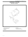
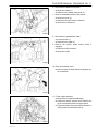
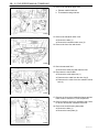
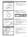
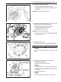
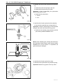
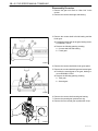
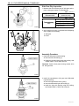
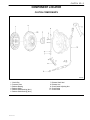
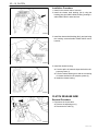
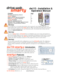
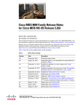
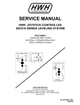
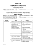
SECTION 5B
FIVE-SPEED MANUAL TRANSAXLE
CAUTION: Disconnect the negative battery cable before removing or installing any electrical unit or when a
tool or equipment could easily come in contact with exposed electrical terminals. Disconnecting this cable
will help prevent personal injury and damage to the vehicle. The ignition must also be in B unless otherwise
noted.
TABLE OF CONTENTS
Description and Operation . . . . . . . . . . . . . . . . . .
Five-Speed Manual Transaxle . . . . . . . . . . . . . . .
Reverse Gear Misshift Preventing
Mechanism . . . . . . . . . . . . . . . . . . . . . . . . . . . . .
Differential . . . . . . . . . . . . . . . . . . . . . . . . . . . . . . . .
5B-2
5B-2
Component Locators . . . . . . . . . . . . . . . . . . . . . . .
Gear Shift Control . . . . . . . . . . . . . . . . . . . . . . . . .
Input Shaft and Counter Shaft Gear . . . . . . . . . .
Gear Shift Fork . . . . . . . . . . . . . . . . . . . . . . . . . . .
5B-3
5B-3
5B-4
5B-6
Differential and Case . . . . . . . . . . . . . . . . . . . . . . .
Diagnostic Information and Procedure . . . . . . .
General Diagnosis . . . . . . . . . . . . . . . . . . . . . . . . .
Checking Fluid Level . . . . . . . . . . . . . . . . . . . . . . .
5B-7
5B-8
5B-8
5B-9
5B-2
5B-2
Changing Fluid . . . . . . . . . . . . . . . . . . . . . . . . . . . . 5B-9
Checking Transaxle Noise . . . . . . . . . . . . . . . . . . 5B-9
Checking Bearing Noise . . . . . . . . . . . . . . . . . . . . 5B-9
Repair Instruction . . . . . . . . . . . . . . . . . . . . . . . . . 5B-10
DAEWOO M-150 BL2
On-Vehicle Service . . . . . . . . . . . . . . . . . . . . . . . . .
Manual Transaxle Assembly . . . . . . . . . . . . . . .
Gear Shift Control Case Assembly . . . . . . . . . .
Speedometer Driven Gear and Cable . . . . . . .
5B-10
5B-10
5B-17
5B-19
Gear Shift Control Cable . . . . . . . . . . . . . . . . . .
Gear Shift Control Lever . . . . . . . . . . . . . . . . . . .
Unit Repair . . . . . . . . . . . . . . . . . . . . . . . . . . . . . . . .
Gear Unit . . . . . . . . . . . . . . . . . . . . . . . . . . . . . . .
5B-21
5B-23
5B-24
5B-24
Input Shaft . . . . . . . . . . . . . . . . . . . . . . . . . . . . . . 5B-36
Counter Shaft . . . . . . . . . . . . . . . . . . . . . . . . . . . . 5B-41
Gear Shift Fork . . . . . . . . . . . . . . . . . . . . . . . . . . 5B-46
Differential . . . . . . . . . . . . . . . . . . . . . . . . . . . . . . .
Specifications . . . . . . . . . . . . . . . . . . . . . . . . . . . .
General Specifications . . . . . . . . . . . . . . . . . . . .
Fastener Tightening Specifications . . . . . . . . . .
5B-48
5B-52
5B-52
5B-53
Special Tools . . . . . . . . . . . . . . . . . . . . . . . . . . . . . 5B-54
Special Tools Table . . . . . . . . . . . . . . . . . . . . . . . 5B-54
5B – 2 FIVE-SPEED MANUAL TRANSAXLE
DESCRIPTION AND OPERATION
FIVE-SPEED MANUAL TRANSAXLE
This five-speed transaxle assembly adopts the synchronized mesh type of 5 forward speed. The reverse speed
gear is driven by sliding idle gear without synchronizer.
REVERSE GEAR MISSHIFT
PREVENTING MECHANISM
It prevents the gear from directly being shifted from 5th
to reverse when shifting to reverse from 5th. Shift to the
reverse in neutral position to prevent the shift cam from
being interfered to the shift guide bolt.
D103B002
When shifting to reverse from neutral position between
5th and reverse, shift cam rotates to left and shifting is
possible.
D103B001
In case of shifting to 5th gear, shift and select shaft rotates to right that shift cam aparts from guide bolt and
moves upwards by returning spring. Therefore, shifting
to reverse in this condition is impossible because of interference of guide bolt.
D103B003
DIFFERENTIAL
Differential is integrated with transmission case and
installed on chassis together with engine. It changes the
direction of power and increase torque by reducing
speed.
Reduction gear is installed parallel to counter shaft and
is helical gear type. Differential gear is bevel gear type
and is integrated with reduction gear.
DAEWOO M-150 BL2
FIVE-SPEED MANUAL TRANSAXLE 5B – 3
COMPONENT LOCATORS
GEAR SHIFT CONTROL
D13B4011
1
2
3
4
Gear Shift Control Lever Knob
Gear Shift Cable Bracket
Select Cable
Shift Cable
DAEWOO M-150 BL2
5 Select Arm
6 Gear Shift Control Lever
7 Gear Shift Control Lever Guide
5B – 4 FIVE-SPEED MANUAL TRANSAXLE
INPUT SHAFT AND COUNTER SHAFT GEAR
D13B4031
DAEWOO M-150 BL2
FIVE-SPEED MANUAL TRANSAXLE 5B – 5
1 Input Shaft Circlip
2 5th Gear Synchronizer Plate
3 5th Gear Synchronizer Sleeve
4 5th Gear Synchronizer Spring
5 5th Gear Synchronizer Key
6 5th Gear Synchronizer Hub
7 5th Gear Synchronizer Ring
7-1 Wave Spring
8 Input Shaft 5th Gear
9 Input Shaft 5th Gear Bearing
10 Input Shaft 5th Gear Spacer
11 Input Shaft Bearing(Left)
12 Input Shaft 4th Gear
13 4th Gear Synchronizer Ring
13-1 Wave Spring
14 Input Shaft 4th Gear Bearing
15 3rd-4th Gear Synchronizer Sleeve
16 3rd-4th Gear Synchronizer Spring
17 3rd-4th Gear Synchronizer Key
18 3rd-4th Gear Synchronizer Hub
19 3rd Gear Synchronizer Ring
20 Input Shaft 3rd Gear
21 Input Shaft 3rd Gear Bearing
22 Input Shaft
23 Input Shaft Bearing(Right)
DAEWOO M-150 BL2
24
25
26
27
28
29
30
31
32
33
34
35
36
37
38
39
40
41
42
43
44
45
46
47
Input Shaft Oil Seal
Reverse Gear Shaft Bolt
Reverse Gear Shaft
Reverse Idle Gear
Counter Shaft Nut
Counter Shaft 5th Gear
Counter Shaft Bearing Shim
Counter Shaft Bearing(Left)
Counter Shaft 4th Gear
Counter Shaft 3rd-4th Gear Spacer
Counter Shaft 3rd Gear
Counter Shaft 2nd Gear
2nd Gear Synchronizer Ring
Counter Shaft 2nd Gear Bearing
1st-2nd Gear Synchronizer Circlip
1st-2nd Gear Synchronizer Sleeve
1st-2nd Gear Synchronizer Spring
1st-2nd Gear Synchronizer Key
1st-2nd Gear Synchronizer Hub
1st Gear Synchronizer Ring
Counter Shaft 1st Gear
Counter Shaft 1st Gear Bearing
Counter Shaft
Counter Shaft Bearing(Right)
5B – 6 FIVE-SPEED MANUAL TRANSAXLE
GEAR SHIFT FORK
D13B4021
1
2
3
4
5
6
7
8
9
10
11
12
13
Shift and Select Shaft
Shift Interlock Bolt
Shift Lever
Select Lever
Shift and Select Shaft Boot
Gearshift Control Case
Shift Guide Bolt
Gearshift Control Case Guide Plate
Gearshift Control Case Gasket
Low Speed Shift Fork
Low Speed Shift Shaft
Low Speed Shift Shaft Spring/Ball
Low Speed Shift York
14
15
16
17
18
19
20
21
22
23
24
25
26
High Speed Shift York
High Speed Shaft Spring/Ball
High Speed Shift Shaft
High Speed Shift Fork
Reverse Shift Arm
5th/Reverse Shift Ball
5th/Reverse Shift Shaft Spring/Ball
Reverse Shift Shaft Guide Spring/Ball
5th/Reverse Shift Shaft
5th/Reverse Shift York
5th/Shift Fork Guide Ball
5th/Shift Fork
Reverse Shift Lever
DAEWOO M-150 BL2
FIVE-SPEED MANUAL TRANSAXLE 5B – 7
DIFFERENTIAL AND CASE
D13B4041
1
2
3
4
5
6
7
8
9
10
11
12
13
Speedometer Driven Gear
Oil Level Plug
Case Cap O–ring(Left)
Case Cap(Left)
Back Up Light Switch
Transaxle Case(Right)
Oil Plate
Transaxle Case(Left)
Oil Drain Plug
Oil Gutter
Side Cover Plate
Side Cover
Differential Ring Gear
DAEWOO M-150 BL2
14
15
16
17
18
19
20
21
22
23
24
25
Differential Oil Seal(Left)
Differential Bearing(Left)
Differential Case
Speedometer Drive Gear
Differential Bearing(Right)
Differential Oil Seal(Right)
Differential Pinion Gear Shaft Pin
Differential Side Gear Adjust Shim
Differential Side Gear
Differential Pinion Gear Shaft
Differential Pinion Gear
Differential Pinion Gear Washer
5B – 8 FIVE-SPEED MANUAL TRANSAXLE
DIAGNOSTIC INFORMATION AND PROCEDURE
GENERAL DIAGNOSIS
Condition
Gear Slipping Out of Mesh
Gear Catching
Hard Shifting
Noise in the Neutral Gear
Noise in the All Gears
Noise in the Peculiar Gear
Leak of Lubricant
Probable Cause
Correction
D Worn shift fork.
D Replace shift fork.
D Worn synchronizer sleeve or gear.
D Replace sleeve or gear.
D Worn bearings on input shaft or
counter shaft.
D Replace bearing.
D Weakened or damaged location
spring.
D Replace spring.
D Loose or damaged synchronizer
spring.
D Replace synchronizer spring.
D Excessive back-lash of gear.
D Adjust back-lash of gear.
D Bent or distorted shift shaft or shift
fork.
D Replace shift shaft or shift fork.
D Weakened or damaged
synchronizer spring.
D Replace spring.
D Worn synchronizer ring.
D Replace synchronizer ring.
D Worn synchronizer sleeve or gear.
D Replace sleeve or gear.
D Bent or distorted shift shaft.
D Replace shift shaft.
D Excessive free travel of all gears
in axial direction.
D Replace gear.
D Worn bearings on input shaft or
counter shaft.
D Replace bearing.
D Poor adjustment of clutch cable.
D Adjust clutch cable.
D Distorted or broken clutch disc.
D Replace clutch disc.
D Damaged pressure plate.
D Replace pressure plate.
D Insufficient lubricant.
D Supply lubricant.
D Worn input shaft gear.
D Replace gear.
D Worn bearings on the input shaft
gears.
D Replace bearing.
D Worn clutch release bearing.
D Replace clutch release bearing.
D Insufficient lubricant.
D Supply lubricant.
D Worn bearings on input shaft or
counter shaft.
D Replace bearing.
D Worn input shaft or counter shaft
gear.
D Replace gear.
D Worn or damaged synchronizer
ring.
D Replace synchronizer ring.
D Worn or damaged synchronizer
sleeve.
D Replace synchronizer sleeve.
D Worn differential gear or bearing.
D Replace gear or bearing.
D Worn or damaged synchronizer
ring in the peculiar gear.
D Replace synchronizer ring.
D Worn or damaged gear in the
peculiar gear.
D Replace gear.
D Worn or damaged bearing in the
peculiar gear.
D Replace bearing.
D Damaged gasket, oil seal or
O-ring.
D Replace gasket, oil seal or O-ing.
DAEWOO M-150 BL2
FIVE-SPEED MANUAL TRANSAXLE 5B – 9
CHECKING FLUID LEVEL
Fluid Specification
Check for a leak in the area of transaxle case and sealing and then check fluid level and condition after removing oil level plug.
1. Operate the engine until it comes to normal operating
temperature(Coolant temperature : 80~90°C (176~
194°F)).
2. Stall the engine and raise the vehicle.
3. Remove the oil level plug and check the fluid level.
Fluid Capacity
2.1L(2.21qt)
Service interval
Refer to Owner’s Manual
4. The fluid should slightly flow out from the oil level plug
hole.
5. If the level is low, add the recommended fluid through
the oil level plug hole until the fluid begins to run out.
6. If the fluid is contaminated or discolored, replace it
with the recommended fluid.
7. Reinstall the oil level plug and tighten it securely.
D103B301
75W-85(GL-4)
CHECKING TRANSAXLE NOISE
Many noises that appear to come from the transaxle
may actually originate with other sources such as tires,
road surfaces, wheel bearings, or engine and exhaust
system.
Identify the cause of any noise before attempting to repair the clutch, the transaxle, or their related linkages.
To verify suspected transaxle noises,
1. Select a smooth, level asphalt road to reduce tyre
and resonant body noise.
2. Drive the vehicle far enough to warm up all the lubricants thoroughly.
3. Record the speed and the gear range of the transaxle
when the noise occurs.
4. Check for noises with the vehicle stopped, but with
the engine running.
5. Determine if the noise occurs while the vehicle operates in.
D Drive – Under a light acceleration or a heavy pull.
D Float – Maintaining a constant speed with a light
throttle on a level road.
D Coast – With the transaxle in gear and the throttle
partly or fully closed.
D All of the above.
CHANGING FLUID
CHECKING BEARING NOISE
1. Operate the engine until it comes to normal operating
temperature(Coolant temperature : 80~90°C (176~
194°F)).
Differential Side Bearing Noise
2. Stall the engine and raise the vehicle.
3. Drain the fluid after removing the drain plug.
4. Reinstall the drain plug and tighten it securely after
coating sealant.
5. Remove the oil level plug and replenish the fluid until
it begins to run out.
a. Oil drain plug.
b. Oil level plug.
6. Reinstall the oil level plug and tighten it securely.
DAEWOO M-150 BL2
Differential side bearing noise and wheel bearing noise
can be confused easily. Since side bearings are preloaded, a differential side bearing noise should not diminish much when the differential/transaxle is run with
the wheels off the ground.
Wheel Bearing Noise
Wheel bearings produce a rough growl or grating sound
that will continue when the vehicle is coasting and the
transaxle is in NEUTRAL. Since wheel bearings are not
pre-loaded, a wheel bearing noise should diminish considerably when the wheels are off the ground.
5B – 10 FIVE-SPEED MANUAL TRANSAXLE
REPAIR INSTRUCTION
ON–VEHICLE SERVICE
MANUAL TRANSAXLE ASSEMBLY
Tools Required
DW110–021 Engine Support Fixture
DW220–031 Transaxle Remove/Install Support
Removal Procedure
1. Remove the air cleaner assembly. Refer to Section
1B, SOHC Engine Mechanical.
2. Remove the battery and battery tray. Refer to Section
1E, Engine Electrical.
3. Disconnect the select and the shift cable.
D103B501
D Remove the cable pins (1).
D Remove the washers (2).
D Disconnect the select and the shift cable (3).
D Remove the cable E–rings (4).
D Disconnect the cables from the cable bracket.
4. Remove the engine wiring harness bending strap.
5. Disconnect the ground wire and the backup lamp
switch connector.
D Remove the ground wire bolt (1).
D Disconnect the ground wire (2).
D Disconnect the backup lamp switch connector (3).
D103B502
DAEWOO M-150 BL2
FIVE-SPEED MANUAL TRANSAXLE 5B – 11
6. Disconnect the radiator lower hose.
D Remove the bolts (1).
D Disconnect the radiator lower hose (2).
7. Remove crankshaft position (CKP) sensor.
D Remove the bolt (3).
D Disconnect the CKP sensor connector
D Remove the CKP sensor.
D13B5031
8. Disconnect the speedometer cable.
D Loosen the nut (1).
D Disconnect the cable (2).
9. Remove the vehicle speed sensor (VSS) if
equipped.
D Disconnect VSS connector.
D Remove the VSS.
D103B507
10. Remove the starter motor.
D Remove upper two bolts that securing starter motor to transaxle.
D102E502
11. Fix the engine assembly.
D Remove the cowl panel weatherstrip.
D Position the engine support fixture DW110–021
on the cowl panel and the front upper panel.
D Tighten the engine fixture joint with a bolt after removing exhaust manifold bolt (No.4).
D13B5041
DAEWOO M-150 BL2
5B – 12 FIVE-SPEED MANUAL TRANSAXLE
12. Remove the transaxle upper bolts.
a. Exhaust manifold side bolt.
b. Thermostat housing side bolt.
D103B510
13. Remove the transaxle under cover.
D Remove the bolts (1).
D Remove the transaxle under cover (2).
14. Remove the front tires and wheels.
D103B505
15. Drain the transaxle fluid.
D Remove the drain plug and drain the fluid.
16. Disconnect the clutch cable.
D Remove the cable adjust nut (1).
D Disconnect the cable from the wire clip (2).
D Disconnect the cable from the transaxle mount
hole (3).
D103B506
17. Remove the front under longitudinal frames and stabilizer. Refer to Section 2C, Front Suspension.
18. Remove the drive axle (only transaxle side). Refer
to Section 3B, Manual Transaxle Drive Axle.
19. Remove the clutch housing lower plate.
D Remove the bolts (1).
D Remove the lower plate (2).
D103B509
DAEWOO M-150 BL2
FIVE-SPEED MANUAL TRANSAXLE 5B – 13
20. Remove the front exhaust pipe.
D Remove the front exhaust pipe nuts (exhaust
manifold side) (1).
D Remove the gasket and separate exhaust manifold pipe (2).
D Make free the front exhaust pipe.
D12B5731
21. Support the transaxle with the transaxle remove/
install support DW220–030N.
D Position the support on the jack (a).
D Support the transaxle case and mount using a
jack and the transaxle remove/install support.
D13B5111
22. Remove the transaxle lower bolt and nut.
a. Lower bolt.
b. Lower nut.
D103B512
23. Remove the transaxle mount bolts.
D13B5131
DAEWOO M-150 BL2
5B – 14 FIVE-SPEED MANUAL TRANSAXLE
24. Position the manual transaxle assembly in tilting.
D To remove the manual transaxle side cover without the interference with the front under longitudinal panel (Left), tilt the engine/manual transaxle by
loosening the engine support fixture DW110– 021
joint with the wrench.
D13B5141
25. Remove the manual transaxle assembly.
D Lower the transaxle assembly slowly by adjusting
jack.
a. Jack.
b. Transaxle assembly.
D Tilt the transaxle assembly by adjusting jack.
D Remove the transaxle assembly by pulling and
lowering it slowly.
D13B5151
26. Support the engine to normal position using the engine support fixture DW110–021.
Notice: The abnormal position of the engine may damage to the related parts or interfere with them. You have
to support the engine to normal position when removing
the transaxle.
Important: If it is impossible to use the special tool, support the engine to normal position with the auto jack.
D103B516
Installation Procedure
1. Install in the reverse order of removal.
2. Install the transaxle mounting bolts.
Tighten
Tighten the transaxle mounting bolts (body side) to
45–55 NSm (33–41 lb-ft).
D13B5171
DAEWOO M-150 BL2
FIVE-SPEED MANUAL TRANSAXLE 5B – 15
3. Install the transaxle lower bolt, nut.
Tighten
Tighten the bolt and nut to 55–65 NSm (41–48 lb-ft).
a. Lower bolt.
b. Lower nut.
D13B518A
4. Tighten the front exhaust pipe nuts.
Tighten
D Tighten the front exhaust pipe nuts (exhaust manifold side) to 25–35 NSm (18–25 lb-ft).
D13B5472
5. Install the transaxle upper bolts.
Tighten
Tighten the bolts to 55–65 NSm (41–48 lb-ft).
a. Exhaust manifold side bolt.
b. Thermostat housing side bolt.
D13B519A
6. Install the starter motor.
Tighten
Tighten the starter motor bolts to 18–28 NSm (13–21
lb-ft).
7. Connect all electric connectors.
D13B548A
DAEWOO M-150 BL2
5B – 16 FIVE-SPEED MANUAL TRANSAXLE
8. Install the radiator lower hose and crank position
(CKP) sensor.
Tighten
Tighten the radiator lower hose bolt to 8–15 NSm
(70–132 lb-in).
Tighten the CKP sensor bolt to 5–8 NSm (44–70 lbin).
D13B5032
9. Refill the transaxle fluid.
D Tighten the drain plug to 25–30 NSm (18–22 lb-ft)
(a).
D Remove the oil level plug (1).
D Refill recommended fluid to the proper level.
ÁÁÁÁÁÁÁÁÁ
ÁÁÁÁÁÁÁÁÁ
ÁÁÁÁÁÁÁÁÁ
ÁÁÁÁÁÁÁÁÁ
ÁÁÁÁÁÁÁÁÁ
Classification
75W – 85 (GL–4)
Capacity
2.1L (2.21 qt)
D Tighten the oil level plug to 36–54 NSm (26–40 lb-ft)
(b).
D13B520A
10. Adjust the clutch cable. Refer to Section 5C, Clutch.
D Adjust the clutch cable by the clutch cable adjust
nut.
11. Install the transaxle under cover.
Tighten
Tighten the transaxle under cover bolts to 35–55
NSm (25–41 lb-ft).
D13B521A
GEAR SHIFT CONTROL CASE
ASSEMBLY
Removal Procedure
D103B501
1. Remove the air hose (air cleaner to throttle body).
Refer to Section 1B, SOHC Engine Mechanical.
2. Remove the battery.
3. Disconnect the select and the shift control cable.
D Remove the cable pins (1).
D Remove the washers (2).
D Disconnect the select and the shift control cable
(3).
D Remove the cable E–rings (4).
D Disconnect the cables from the cable bracket.
DAEWOO M-150 BL2
FIVE-SPEED MANUAL TRANSAXLE 5B – 17
4. Remove the select lever.
D Remove the bolts (1).
D Remove the select lever (2).
D103B522
5. Remove the shift interlock bolt.
Important: Certainly remove the shift interlock bolt.
Otherwise, the gear shift control case can not be removed.
D103B523
6. Remove the gear shift control case assembly.
D Remove the bolts (1).
Important: Make sure the gear shift lever is in NEUTRAL.
D Remove the gear shift control case assembly (2).
D Remove the gasket (3).
D103B524
7. Remove the shift lever.
D Position the gear shift control case assembly to the
vice with a protector.
D Remove the lever pin with a pin punch and a hammer (1).
D Remove the shift lever (2).
D Remove the boot (3).
D103B525
DAEWOO M-150 BL2
5B – 18 FIVE-SPEED MANUAL TRANSAXLE
8. Remove the select/shift shaft.
D Remove the shift guide bolt (1).
D Remove the select/shift shaft (2).
D103B526
9. Remove the gear shift control case plate.
D Remove the bolts (1).
D Remove the Plate from the case (2).
D103B527
Inspection Procedure
1. Inspect for worn or damaged the fifth/reverse shift
cam (1).
2. Inspect for worn or damaged shift interlock plate (2).
3. Inspect for worn or damaged select/shift lever (3).
4. Inspect for bent or damaged select/shift shaft (4).
D103B528
Installation Procedure
1. Install in the reverse order of removal.
2. Install the shift guide bolt.
Tighten
Tighten the shift guide bolt to 18–28 NSm (13–21 lb-ft).
D13B529A
DAEWOO M-150 BL2
FIVE-SPEED MANUAL TRANSAXLE 5B – 19
3. Install the gear shift control case and the select lever.
Tighten
D Tighten the gear shift control case bolts to 18–28
NSm (13–21 lb-ft).
a. Gear shift control case bolt.
D Tighten the select lever bolts to 18–28 NSm (13–21
lb-ft).
b. Select lever bolt.
Important: Make sure a correct bolt. There is length difference between select lever bolts.
D13B530A
4. Install the shift interlock bolt.
Tighten
Tighten the shift interlock bolt to 18–28 NSm (13–21
lb-ft).
D13B531A
SPEEDOMETER DRIVEN GEAR AND
CABLE
(Left–Hand Drive Shown, Right–Hand
Drive Similar)
Removal Procedure
1. Remove the speedometer driven gear assembly.
D
D
D
D
D103B532
Loosen the nut. (1).
Disconnect the cable (2).
Remove the bolt (3).
Remove the speedometer driven gear assembly
(4).
D Disconnect the vehicle speed sensor connector (If
equipped).
a. Vehicle speed sensor connector.
D Disconnect the vehicle speed sensor.
b. Vehicle speed sensor.
Caution: Be careful to prevent personal injury while
the exhaust pipe is hot.
D103B533
DAEWOO M-150 BL2
5B – 20 FIVE-SPEED MANUAL TRANSAXLE
2. Remove the battery. Refer to Section 1E, Engine
Electrical.
3. Disconnect the instrument cluster side cable. Refer to
Section 9E, Instrumentation/Driver Information.
4. Remove the speedometer cable.
D Remove the cable grommet (1).
D Pull out the speedometer cable from the dash panel.
D103B534
Inspection Procedure
1. Remove the O–ring from the speedometer driven
gear housing.
2. Remove the driven gear pin and disconnect the driven gear.
D Check for a damaged or torn O–ring.
D Check for a worn or damaged tooth of driven gear.
a. O–ring.
b. Driven gear pin.
c. Driven gear.
D103B535
Installation Procedure
1. Install in the reverse order of removal.
Important: Install the speedometer driven gear assembly after connecting the speedometer cable with the
speedometer driven gear assembly completely.
D103B536
2. Install the speedometer driven gear assembly to
transaxle housing.
Tighten
Tighten the speedometer driven gear assembly bolt
to 4–7 NSm (35–62 lb-in).
D13B537A
DAEWOO M-150 BL2
FIVE-SPEED MANUAL TRANSAXLE 5B – 21
GEAR SHIFT CONTROL CABLE
Removal Procedure
D103B501
1. Remove the air hose (air cleaner to throttle body).
Refer to Section 1B, SOHC Engine Mechanical.
2. Remove the battery.
3. Disconnect the transaxle side select and shift control
cable.
D Remove the cable pins (1).
D Remove the washers (2).
D Disconnect the select and shift control cable (3).
D Remove the cable E–rings (4).
D Disconnect the cables from the cable bracket.
4. Remove the floor console. Refer to Section 9G, Interior Trim.
D Put aside the floor carpet in order to get the gear
shift cable shown.
D19E573A
5. Disconnect the gear shift lever side select and shift
control cable.
D Remove the select control cable clip (1).
D Ply off the eye ring (2).
D Remove the select control cable E–ring (3).
D
D
D
D
Disconnect the select control cable (4).
Remove the shift control cable pin (5).
Remove the shift control cable E–ring (6).
Ply off the shift control cable (7).
D13B5381
6. Remove the select and shift control cable.
D Remove the nuts (1).
D Pull the cables out in the passenger room.
D13B539A
DAEWOO M-150 BL2
5B – 22 FIVE-SPEED MANUAL TRANSAXLE
Installation Procedure
1. Install in the reverse order of removal.
2. Push the cables toward the engine compartment
through dash panel’s hole slightly.
3. Position the cables on the select and the shift lever.
D103B540
4. Connect the transaxle side select and shift control
cable.
5. Connect the gear shift lever side shift control cable.
6. Connect the gear shift lever side select control cable.
D Insert the select control cable eye ring to the select
arm pin (1).
D Install the selector lever control cable clip (2).
D Install the select control cable to gear shift lever
bracket with E–ring (3).
D13B5411
D Insert a driver to the select arm adjustment hole to
prevent the movement of gear shift lever in NEUTRAL (4).
7. Tighten the adjust nuts.
Tighten
Tighten the select cable adjust nut to 8–12 NSm
(71–106 lb-in).
GEAR SHIFT CONTROL LEVER
Removal Procedure
1. Remove the floor console. Refer to Section 9G, Interior Trim.
2. Disconnect the select and shift control cable. Refer to
“Gear Shift control cable” in this section.
3. Remove the gear shift control lever assembly.
D Remove the bolts (1).
D Remove the gear shift control lever assembly (2).
D Remove the gear shift lever sensor connector.
(If equipped with auto clutch).
D103B543
DAEWOO M-150 BL2
FIVE-SPEED MANUAL TRANSAXLE 5B – 23
Installation Procedure
1. Install in the reverse order of removal.
2. Install the gear shift control lever assembly.
Tighten
Tighten the bolts to 4–7 NSm (35–62 lb-in).
3. Adjust the select cables. Refer to “Gear Shift Control
Cable” in this section.
D13B544A
DAEWOO M-150 BL2
5B – 24 FIVE-SPEED MANUAL TRANSAXLE
MAINTENANCE AND REPAIR
UNIT REPAIR
GEAR UNIT
Tools Required
09913–76010
DW09940–53111
DW09943–78210
DW220–010A
KM519
Bushing, Seal Installer
Gear, Bearing Installer
Bushing, Seal Installer
Transaxle Fixture
Oil Seal Installer
Disassembly Procedure
D13B701A
1. Remove the manual transaxle. Refer to “Manual
Transaxle Assembly” in this section.
2. Position the manual transaxle to a transaxle stand using the transaxle fixture DW220–010.
3. Remove the related clutch parts. Refer to Section 5C,
Clutch.
4. Remove the manual transaxle mounting bracket.
D Remove the bolts (1).
D Remove the nut (2).
D Remove the mounting bracket (3).
D13B7021
5. Disconnect the backup light switch and speedometer
driven gear assembly.
D Remove the nut (1).
D Disconnect the backup light switch (2).
D Remove the bolt (3).
D Remove the speedometer driven gear assembly
(4).
D103B703
DAEWOO M-150 BL2
FIVE-SPEED MANUAL TRANSAXLE 5B – 25
6. Remove the select lever.
D Remove the bolt (1).
D Remove the select lever (2).
D103B704
7. Remove the gear shift control case assembly.
D Remove the bolts (1).
D Remove the shift interlock bolt (2).
Important: Certainly remove the shift interlock bolt.
Otherwise, gear shift control case can not be removed.
D Remove the gear shift control case assembly (3).
D Remove the gasket (4).
D103B705
8. Remove the side cover.
D Remove the bolts (1).
D Remove the side cover using a rubber hammer (2).
D Remove the sealant on the side cover and the
transaxle case.
D103B706
9. Remove the fifth–gear shift fork guide ball, the snap
ring and the input shaft fifth–gear snap ring.
D Remove the fifth–gear shift fork plug (1).
D Remove the guide ball using a magnet.
D Remove the fifth–gear shift fork snap ring (2).
D Remove the fifth–gear snap ring (3).
D Remove the fifth–gear synchronizer plate.
D103B707
DAEWOO M-150 BL2
5B – 26 FIVE-SPEED MANUAL TRANSAXLE
10. Remove the fifth–gear shift fork pin.
D Shift the shift fork to the fifth–gear.
D Remove the fork pin using a pin punch and a
hammer (1).
D103B708
11. Remove the input shaft fifth–gear fork and synchronizer hub assembly.
D Pull and remove the fork and the hub assembly
together (1).
D Remove the sleeve, key and spring from the synchronizer hub assembly.
D103B709
12. Remove the input shaft fifth–gear, the synchronizer
ring and the fifth–gear bearing.
D Pull and remove the fifth–gear, wave spring and
synchronizer ring together (1).
D Remove the fifth–gear bearing.
D103B710
13. Remove the countershaft fifth–gear.
D Shift the shift yoke using a driver to engage the
first–gear and the third–gear or the second–gear
and the fourth–gear (1).
D Remove the caulking and the nut. (2, 3)
D103B711
DAEWOO M-150 BL2
FIVE-SPEED MANUAL TRANSAXLE 5B – 27
D Remove the counter shaft fifth–gear (4).
D103B712
14. Remove the side cover plate and the counter shaft
bearing shim.
D Remove the screws (1).
D Remove the side cover plate (2).
D Remove the counter shaft bearing shim.
D103B713
15. Remove the shift shaft spring and ball.
D Remove the bolt and remove the fifth–reverse
gear shift shaft spring and ball (1).
D Remove the bolt and remove the third–fourth
gear shift shaft spring and ball (2).
D Remove the bolt and remove the first–second
gear shift shaft spring and ball (3).
Important: There is difference between the fifth–reverse gear shift shaft spring and the others. Mark it to
distinguish easily when installing.
D103B714
16. Remove the reverse idle gear shaft bolt.
Important: The case (Left) can not be removed without
removing the reverse idle gear shaft bolt.
D103B715
DAEWOO M-150 BL2
5B – 28 FIVE-SPEED MANUAL TRANSAXLE
17. Remove the transaxle case (Left).
D Remove the bolts from the left side case (1).
D Remove the bolts, stud bolts if equipped with
auto clutch.
D Remove the bolts from the right side of case (2).
D Remove the left side case by hitting with a rubber
hammer lightly.
D Remove the sealant on the case.
D103B716
18. Remove the reverse gear shift lever.
D Remove the bolts (1).
D Remove the reverse gear shift lever (2).
D103B717
19. Remove the reverse idle gear shaft assembly.
D Push the reverse idle gear toward inner case.
D Pulling shaft and remove the reverse idle gear
and shaft (1).
D Remove the reverse idle gear from the shaft.
D103B718
20. Remove the fifth–reverse gear shift shaft.
a. Fifth–reverse gear shift shaft.
D103B719
DAEWOO M-150 BL2
FIVE-SPEED MANUAL TRANSAXLE 5B – 29
21. Remove the gear unit.
D Remove the gear unit and the shift shaft assembly together (1).
Notice: Be careful not to damage teeth of the counter
shaft pinion and the differential ring gear.
D Remove the high and the low speed shift shaft
assembly from the gear unit.
D103B720
22. Remove the differential assembly.
D Insert a wooden stick into the lower side of differential (1).
D Remove the differential assembly by moving it
right and left (2).
D103B721
23. Remove the related parts of the transaxle case (Left
Side).
D
D
D
D
D
Remove the bolt (1).
Remove the oil gutter (2).
Remove the bolts (3).
Remove the oil plate (4).
Remove the differential left side oil seal using a
hammer and a copper chisel (5).
D103B722
D
D
D
D
Remove the bolts (6).
Remove the case cap (Left Side) (7).
Remove the case cap O–ring (Left Side) (8).
Remove the oil level plug (including steel gasket)
(9).
D Remove the counter shaft bearing outer race using a hammer and the gear, bearing installer DW
09940–53111.
D103B723
DAEWOO M-150 BL2
5B – 30 FIVE-SPEED MANUAL TRANSAXLE
24. Remove the related parts of the transaxle case
(Right Side).
D Remove the input shaft oil seal using a screwdriver (1).
D Remove the differential left side oil seal using a
hammer and a copper chisel (2).
D103B724
Synchronizer Sleeve and Shift Fork
Inspection
1. Measure the clearance between synchronizer sleeve
and shift fork and if the clearance exceeds the limit,
replace the shift fork.
Unit : mm (in.)
ÁÁÁÁÁÁÁ
ÁÁÁÁÁÁ
ÁÁÁÁÁÁ
ÁÁÁÁÁÁÁ
ÁÁÁÁÁÁ
ÁÁÁÁÁÁ
ÁÁÁÁÁÁÁ
ÁÁÁÁÁÁÁ
Clearance Between
Sleeve and Shift
Fork
Standard
Limit
0.2 ∼0.6
(0.008∼0.024)
1.0
(0.039)
D103B725
Assembly Procedure
1. Install the related parts of the transaxle case (Right
Side).
D Install the input shaft oil seal using the bushing
seal installer DW09943–78210.
D Install the differential right side oil seal using the
bushing, seal installer 09913–76010.
Important: Use only a new oil seal.
Important: Coat the transaxle inner parts with gear fluid
when installing.
D103B726
2. Install the related parts of the transaxle case (Left
Side).
D Install the oil plate with the bolts.
D Install the oil gutter with the bolt.
D Install the oil level plug (including steel gasket).
a. Oil level plug.
Tighten
Tighten the oil level plug to 36–54 NSm (26–40 lb-ft).
D Install the left side case cap with the bolts (including O–ring) (1).
D13B727A
DAEWOO M-150 BL2
FIVE-SPEED MANUAL TRANSAXLE 5B – 31
Tighten
Tighten the bolt to 8–12 NSm (71–106 lb-in).
b. Case cap retaining bolt.
D Install the differential left side oil seal using the oil,
seal installer KM519.
D13B727A
3. Install the differential assembly to the right side of
transaxle case.
a. Differential assembly.
D When the differential ring gear surface is lower
than the right side of transaxle case surface, it is
installed correctly.
D103B728
4. Install the low and the high speed shift shaft assembly to the gear unit.
5. Install the gear unit.
D Push the gear unit by matching it with the input and
the counter shaft hole (1).
Notice: Be careful not to damage teeth of the counter
shaft pinion and the differential ring gear.
D103B729
6. Install the fifth–reverse gear shift shaft.
7. Install the reverse idle gear shaft assembly and the
reverse gear shift lever.
D Install the reverse idle gear shaft assembly (1).
Important: Match the marking of the reverse idle gear
shaft bolt hole with the protrusion of the transaxle case
(Right Side).
D Install the reverse gear shift lever (2).
Tighten
Tighten the bolts to 18–28 NSm (13–21 lb-ft).
D13B730A
DAEWOO M-150 BL2
5B – 32 FIVE-SPEED MANUAL TRANSAXLE
8. Install the shift shaft ball and spring.
D Install the third–fourth gear shift shaft ball and
spring.
Tighten
Tighten the bolt to 10–16 NSm (7–12 lb-ft) (a).
D Install the fifth–reverse gear shift shaft ball and
spring.
Tighten
Tighten the bolt to 10–16 NSm (7–12 lb-ft) (b).
D13B731A
Important: Install the fifth–reverse gear shift shaft
spring marked when removing.
9. Install the transaxle left side case.
D Coat the transaxle case with recommended sealant.
ÁÁÁÁÁÁÁÁÁ
ÁÁÁÁÁÁÁÁÁ
ÁÁÁÁÁÁÁÁÁ
ÁÁÁÁÁÁÁÁÁ
Transaxle Case Sealant
THREE BOND 1215
D Install the transaxle left side case to the transaxle
right side case.
Tighten
D13B732A
Tighten the bolts to 15–22 NSm (11–16 lb-ft) (a).
D Tighten the bolts (8), stud bolts (3) if equipped with
auto clutch.
Tighten the bolts to 15–22 NSm (11–16 lb-ft) (b).
10. Install the first–second gear shift shaft ball and
spring.
Tighten
Tighten the bolt to10–16 NSm (7–12 lb-ft) (a).
11. Install the reverse idle gear shaft bolt.
Tighten
Tighten the bolt to 18–28 NSm (13–21 lb-ft) (b).
D13B733A
12. Install the counter shaft bearing outer race.
D Install the counter shaft bearing outer race using
the gear, bearing installer DW09940–53111.
a. Bearing outer race.
Important: Check if the bearing and the outer race are
correctly installed by rotating counter shaft.
D103B734
DAEWOO M-150 BL2
FIVE-SPEED MANUAL TRANSAXLE 5B – 33
13. Install the counter shaft bearing shim.
D Measure clearance between the transaxle case
surface and the bearing outer race using a
straight ruler and gauge.
D Select shim in order that clearance is within standard.
Unit : mm (in.)
Measured value (A)
Shim thickness
D13B735A
ÁÁÁÁÁÁÁÁÁÁÁ
ÁÁÁÁÁÁÁ
ÁÁÁÁÁÁÁÁÁÁÁ
ÁÁÁÁÁÁÁ
ÁÁÁÁÁÁÁÁÁÁÁ
ÁÁÁÁÁÁÁ
ÁÁÁÁÁÁÁÁÁÁÁ
ÁÁÁÁÁÁÁ
ÁÁÁÁÁÁÁÁÁÁÁ
ÁÁÁÁÁÁÁ
ÁÁÁÁÁÁÁÁÁÁÁ
ÁÁÁÁÁÁÁ
ÁÁÁÁÁÁÁÁÁÁÁ
ÁÁÁÁÁÁÁ
ÁÁÁÁÁÁÁÁÁÁÁ
ÁÁÁÁÁÁÁ
ÁÁÁÁÁÁÁÁÁÁÁ
ÁÁÁÁÁÁÁ
ÁÁÁÁÁÁÁÁÁÁÁ
ÁÁÁÁÁÁÁ
ÁÁÁÁÁÁÁÁÁÁÁ
ÁÁÁÁÁÁÁ
ÁÁÁÁÁÁÁÁÁÁÁ
ÁÁÁÁÁÁÁ
ÁÁÁÁÁÁÁÁÁÁÁ
ÁÁÁÁÁÁÁ
ÁÁÁÁÁÁÁÁÁÁÁ
ÁÁÁÁÁÁÁ
ÁÁÁÁÁÁÁÁÁÁÁ
ÁÁÁÁÁÁÁ
ÁÁÁÁÁÁÁÁÁÁÁ
ÁÁÁÁÁÁÁ
ÁÁÁÁÁÁÁÁÁÁÁ
ÁÁÁÁÁÁÁ
0.33 − 0.37 (0.0130 – 0.0146)
0.45 (0.0177)
0.38 − 0.42 (0.0147 – 0.0165)
0.50 (0.0197)
0.43 − 0.47 (0.0169 – 0.0185)
0.55 (0.0217)
0.48 − 0.52 (0.0189 – 0.0205)
0.60 (0.0236)
0.53 − 0.57 (0.0209 – 0.0224)
0.65 (0.0256)
0.58 − 0.62 (0.0228 – 0.0244)
0.70 (0.0276)
0.63 − 0.67 (0.0248 – 0.0264)
0.75 (0.0295)
0.68 − 0.72 (0.0268 – 0.0283)
0.80 (0.0315)
0.73 − 0.77 (0.0287 – 0.0303)
0.85 (0.0335)
0.78 − 0.82 (0.0307 – 0.0323)
0.90 (0.0354)
0.83 − 0.87 (0.0327 – 0.0343)
0.95 (0.0374)
0.88 − 0.92 (0.0346 – 0.0362)
1.00 (0.0394)
0.93 − 0.97 (0.0366 – 0.0382)
1.05 (0.0413)
0.98 – 1.02 (0.0386 – 0.0402)
1.10 (0.0433)
1.03 – 1.07 (0.0406 – 0.0421)
1.15 (0.0453)
a. Straight ruler
b. Bearing outer race
c. Case surface
14. Install the side cover plate and the counter shaft fifth
gear.
D Install the side cover plate (1).
Tighten
Tighten the screws to 6–7 N.m (53–62 lb–in).
Important: Use only new screws.
D Install the counter shaft fifth gear (2).
Important: Position the machined boss side toward the
side cover plate.
D13B736A
DAEWOO M-150 BL2
5B – 34 FIVE-SPEED MANUAL TRANSAXLE
15. Install the counter shaft fifth gear nut.
D Shift the shift yoke using a screwdriver to engage
the first–gear and the third–gear or the second–
gear and the fourth–gear (1).
Tighten
Tighten the fifth gear nut to 60–80 NSm (44–59 lb-ft).
D Caulk the nut using a chisel and a hammer (2).
D13B737A
16. Install the input shaft fifth gear bearing and the fifth
gear / synchronizer ring.
D Insert the bearing into the input shaft.
D Install the fifth gear, wave spring and synchronizer ring matching synchronizer’s oil groove and input shaft punched mark (1).
D103B710
17. Install the fifth gear synchronizer hub assembly.
D Install the synchronizer springs to hub (1).
D Install the synchronizer key (2).
Important: In case of assembling synchronizer sleeve
and hub, let A=B.
D Position the longer boss side of hub toward inner
side (3).
D Position the chamfered spline of sleeve toward
inner side and install the hub to the sleeve (4).
D103B738
18. Install the fifth gear fork to the synchronizer hub assembly.
19. Install the fifth gear fork and the synchronizer hub
assembly to the input shaft.
Important: Position the longer boss side of hub toward
inner side and match the synchronizer key and the hub
groove with the input shaft punched mark.
D103B739
DAEWOO M-150 BL2
FIVE-SPEED MANUAL TRANSAXLE 5B – 35
20. Install the fifth gear shift fork pin.
D Push the shift fork toward the fifth gear.
D Install the shift fork pin using a pin punch and a
hammer(1).
Important: Use only new shift fork pin.
D103B740
21. Install the input shaft fifth gear snap ring, the fifth
gear shift fork snap ring and guide ball.
D Install the fifth gear synchronizer plate.
D Install the fifth gear snap ring (1).
D Install the fork snap ring (2).
Important: Use only new snap ring.
D Tighten the fork plug after inserting the guide ball
into the fork hole.
D103B741
22. Install the side cover(1).
D Coat the side cover with recommended sealant.
ÁÁÁÁÁÁÁÁÁ
ÁÁÁÁÁÁÁÁÁ
ÁÁÁÁÁÁÁÁÁ
ÁÁÁÁÁÁÁÁÁ
Side Cover Sealant
THREE BOND 1215
Tighten
Tighten the side cover bolts to 8–12 NSm (71–106
lb-in).
D13B742A
23. Install the gear shift control case assembly.
D Install the case gasket.
D Install the gear shift control case.
Tighten
D Tighten the bolts to 18–28 NSm (13–21 lb-ft) (a).
D Tighten the shift interlock bolt to 18–28 NSm (13–
21 lb-ft) (b).
D Install the select lever.
Tighten
Tighten the bolts to 18–28 NSm (13–21 lb-ft) (c).
D13B743A
DAEWOO M-150 BL2
5B – 36 FIVE-SPEED MANUAL TRANSAXLE
24. Install the backup light switch and the speedometer
driven gear assembly.
D Install the backup light switch (1).
Tighten
Tighten the nut to 15–18 NSm (11–13 lb-ft) (a).
D Install the speedometer driven gear assembly
(2).
Tighten
D13B744A
Tighten the bolt to 4–7 NSm (35–62 lb-in) (b).
D Install the hydraulic pump assembly (If equipped
with auto clutch). Refer to Section 5D, Auto
Clutch.
25. Install the transaxle mount.
D Install the mount (1).
Tighten
D Tighten the bolts to 55–65 NSm (41–48 lb-ft) (a).
D Tighten the nut to 55–65 NSm (41–48 lb-ft) (b).
D13B7452
26. Install the related clutch parts. Refer to Section 5C,
Clutch.
27. Remove the transaxle assembly from transaxle
stand.
D Remove the transaxle assembly using the transaxle fixture DW220–010A.
28. Install the transaxle assembly. Refer to “Manual
Transaxle Assembly” in this section.
D13B701A
INPUT SHAFT
Tools Required
DW09921–57810 Gear, Bearing Remover
DW09925–98221 Gear, Bearing Installer
DW09940–53111 Gear, Bearing Installer
Disassembly Procedure
D103B746
1. Remove the gear unit. Refer to “Gear Unit” in this
section.
2. Remove the input shaft right side bearing.
D Position the bearing to the gear, bearing remover
DW09921–57810.
D Remove the bearing by pressing (1).
DAEWOO M-150 BL2
FIVE-SPEED MANUAL TRANSAXLE 5B – 37
3. Remove the input shaft fifth gear spacer, the left side
bearing and the fourth gear.
D Position the fourth gear to the gear,bearing remover DW09921–57810.
D Remove the following parts.
a. Fifth gear spacer.
b. Left side bearing.
c. Fourth gear
D103B747
4. Remove the fourth gear bearing.
5. Remove the fourth gear synchronizer ring and wave
spring.
D103B748
6. Remove the third–fourth synchronizer circlip.
D103B749
7. Remove the third–fourth synchronizer hub assembly,
the third gear 1 synchronizer ring.
D Position the third gear to the gear, bearing remover
DW09921–57810.
D Remove the following parts.
a. Third–fourth synchronizer hub assembly.
b. Third gear and synchronizer ring.
D103B750
DAEWOO M-150 BL2
5B – 38 FIVE-SPEED MANUAL TRANSAXLE
8. Disassemble the third–fourth synchronizer hub assembly.
D Remove the hub (1).
D Remove the synchronizer sleeve and the key (2).
D Remove the synchronizer springs (3).
D103B751
9. Remove the input shaft third gear bearing (1).
D103B752
Synchronizer Assembly Inspection
1. Inspecting wear of cone area.
D After matching synchronizer ring to gear, measure
as shown in figure. Replace if it is below limit.
Unit : mm (in.)
Standard
Limit
Clearance Between
Gear and Ring
1.0 (0.039)
0.5 (0.020)
ÁÁÁÁÁÁÁ
ÁÁÁÁÁÁ
ÁÁÁÁÁÁ
ÁÁÁÁÁÁ
ÁÁÁÁÁÁ
ÁÁÁÁÁÁÁ
ÁÁÁÁÁÁÁ
D103B753
2. Inspecting cone contact condition.
D When synchronizer mechanism is abnormal in operation, connection between ring inner surface and
gear cone area is considered to be partially defective in spite of correct clearance between gear and
ring. Therefore, cone area and ring inner surface
shall be inspected. In this case, ring inner surface
shall be glossy. Black area is abnormal and if inspection is difficult, check after applying red lead.
Cone area can be worn in wave form.
D103B754
DAEWOO M-150 BL2
FIVE-SPEED MANUAL TRANSAXLE 5B – 39
3. Inspecting key slot width of synchronizer ring.
D Measure key slot width of synchronizer ring. Replace if it exceeds limit.
ÁÁÁÁÁÁÁÁÁÁÁÁÁÁÁÁÁ
ÁÁÁÁÁÁÁ
ÁÁÁÁÁÁ
ÁÁÁÁÁÁ
ÁÁÁÁÁÁ
ÁÁÁÁÁÁ
ÁÁÁÁÁÁÁ
ÁÁÁÁÁÁÁ
ÁÁÁÁÁÁÁ
ÁÁÁÁÁÁÁ
Unit : mm (in.)
Key Slot Width
Standard
Limit
1st gear
8.2 (0.323)
8.6 (0.339)
2nd, 3rd, 4th gear
9.6 (0.378)
10.0 (0.394)
5th gear
9.4 (0.370)
9.8 (0.386)
D103B755
4. Inspecting wear of synchronizer ring.
D Check for worn or damaged synchronizer ring
teeth. Replace it if necessary.
D103B756
5. Inspecting synchronizer key and spring.
D Check for worn synchronizer key (1).
D Check for weak, damaged or broken spring (2).
D103B757
Assembly Procedure
1. Install the third gear bearing, the third gear / synchronizer ring.
a. Third gear / synchronizer ring.
b. Third gear bearing.
Important: Coat the inner parts; gear, bearing, oil seal
etc. with gear fluid.
D103B758
DAEWOO M-150 BL2
5B – 40 FIVE-SPEED MANUAL TRANSAXLE
2. Assemble the third–fourth synchronizer hub assembly.
D Install the synchronizer springs to the hub.
D Install the synchronizer key to the hub.
Important: In case of assembling the synchronizer
sleeve and the hub, let A=B.
D Install the hub to the sleeve.
a. Sleeve.
b. Hub.
D103B759
3. Install the third–fourth synchronizer hub assembly.
D Insert the hub assembly into the input shaft (1).
Important: Position the longer flange of hub toward the
third gear and match the key and the ring groove.
D Install the hub assembly using a hammer and the
gear, bearing installer DW09940–53111.
D103B760
Notice: When installing gear, bearing and hub assembly, install them slowly using the gear, bearing installer
DW09940–53111 and a hammer. If overpressed, the
gear teeth may be damaged.
D13B761A
4. Install the third–fourth synchronizer circlip.
5. Install the fourth synchronizer ring and wave spring.
Important: Match the ring groove to the key of hub.
D103B749
DAEWOO M-150 BL2
FIVE-SPEED MANUAL TRANSAXLE 5B – 41
6. Install the input shaft fourth gear bearing and the
fourth gear.
a. Fourth gear.
b. Fourth gear bearing.
D103B762
7. Install the input shaft left side bearing and the fifth
gear spacer.
D Install the following parts using the gear, bearing
installer DW09925–98221 and a hammer.
a. Fifth gear spacer.
b. Input shaft left side bearing.
D103B763
8. Install the input shaft right side bearing.
D Install the bearing to the input shaft using the gear,
bearing installer DW09925–98221 and a hammer
(1).
9. Install the gear unit. Refer to “Gear Unit” in this section.
D103B764
COUNTER SHAFT
Tools Required
09913–76010
Bushing, Seal Installer
DW09913–80112 Gear, Bearing Installer
D103B765
DAEWOO M-150 BL2
DW09921–57810
DW09925–98221
DW09940–53111
DW220–020–01
Gear, Bearing Remover
Gear, Bearing Installer
Gear,Bearing Installer
Differential Bearing Puller
DW220–020–02
DW220–020–03
KM466–A
Differential Bearing Plate Adapter
Differential Bearing Plate Adapter
Gear, Bearing Remover/Installer
5B – 42 FIVE-SPEED MANUAL TRANSAXLE
Disassembly Procedure
1. Remove the gear unit. Refer to “Gear Unit” in this
section.
2. Remove the counter shaft right side bearing.
3. Remove the counter shaft left side bearing and the
fourth gear.
D Position the fourth gear to the gear, bearing remover DW09921–57810.
D Remove the following parts by pressing.
a. Counter shaft left side bearing.
b. Fourth gear.
D103B766
4. Remove the counter shaft third–fourth gear spacer.
5. Remove the counter shaft third gear and second gear.
D Position the second gear to the gear, bearing remover DW09921–57810.
D Remove the following parts by pressing
a. Third gear.
b. Second gear.
D103B767
6. Remove the counter shaft second gear bearing.
7. Remove the second gear synchronizer ring.
8. Remove the first–second gear synchronizer circlip.
D103B768
DAEWOO M-150 BL2
FIVE-SPEED MANUAL TRANSAXLE 5B – 43
9. Remove the counter shaft first–second gear synchronizer hub assembly, the first gear / the first gear
synchronizer ring.
D Position the first gear to the gear, bearing remover DW09921–57810.
D Remove the following parts by pressing.
a. Synchronizer hub assembly.
b. First gear / First gear synchronizer ring.
D Remove the first gear synchronizer ring from the
first gear.
D103B769
10. Disassemble the first–second gear synchronizer
hub assembly.
D Push the hub from the hub assembly (1).
D Disassemble the synchronizer sleeve and key
(2).
D Disassemble the synchronizer springs (3).
D103B770
11. Remove the counter shaft first gear bearing.
D103B771
Synchronizer Hub and Sleeve Inspection
D Check the sleeve for improper operation after assembling the hub and the sleeve.
D Check the wear of hub and sleeve.
D Replace synchronizer hub or sleeve if necessary.
D103B772
DAEWOO M-150 BL2
5B – 44 FIVE-SPEED MANUAL TRANSAXLE
Assembly Procedure
1. Install the related counter shaft first gear.
D Install the first gear bearing (1).
D Install the first gear (2).
D Install the first gear synchronizer ring (3)
Important: Coat the inner parts; gear, bearing and oil
seal etc. with gear fluid.
Important: Be careful there is the difference of key
groove width between the first synchronizer ring and the
second synchronizer ring.
D103B773
ÁÁÁÁÁÁÁÁÁ
ÁÁÁÁÁÁÁÁÁ
ÁÁÁÁÁÁÁÁÁ
ÁÁÁÁÁÁÁÁÁ
ÁÁÁÁÁÁÁÁÁ
ÁÁÁÁÁÁÁÁÁ
ÁÁÁÁÁÁÁÁÁ
ÁÁÁÁÁÁÁÁÁ
Key Groove Width
Unit : mm (in.)
First synchronizer ring (A)
: 8.2 (0.323)
Second synchronizer ring
(B) : 9.6 (0.378)
D103B774A
2. Assemble the first–second synchronizer hub assembly.
D Install the synchronizer springs to hub.
D Install the synchronizer keys to hub.
Important: Let (A)=(B) when installing the keys.
D Install the hub to the sleeve.
a. Sleeve.
b. Hub.
D103B775
3. Install the first–second synchronizer hub assembly.
D Insert the hub assembly into the counter shaft using the gear, bearing installer DW09940–53111,
the gear bearing remover/installer KM466–A and a
hammer (1).
Important: Position the synchronizer key to the first
gear synchronizer ring groove.
D103B776
DAEWOO M-150 BL2
FIVE-SPEED MANUAL TRANSAXLE 5B – 45
4. Install the second synchronizer ring.
Important: Position the second synchronizer ring groove
to the synchronizer hub key.
5. Install the first–second gear synchronizer circlip.
D103B768
6. Install the related counter shaft second gear.
D Install the second gear bearing (1).
D Install the second gear (2).
D103B777
7. Install the counter shaft third gear and the third–fourth
gear spacer.
D Insert the third gear and the third–fourth gear
spacer into the counter shaft.
D Install the following parts using the gear, bearing
installer DW09913–80112 and a hammer.
a. Third–fourth gear spacer.
b. Third gear.
D103B778
8. Install the counter shaft fourth gear.
D Install the fourth gear to the counter shaft using the
gear, bearing installer DW09925–98221 and a
hammer (1).
D103B779
DAEWOO M-150 BL2
5B – 46 FIVE-SPEED MANUAL TRANSAXLE
9. Install the counter shaft left side bearing.
D Install the left side bearing to the counter shaft using the gear, bearing installer DW09925–98221
and a hammer (1).
D103B780
10. Install the counter shaft right side bearing.
11. Install the gear unit. Refer to “Gear Unit” in this section.
D103B765
GEAR SHIFT FORK
Disassembly Procedure
1. Remove the gear unit. Refer to “Gear Unit” in this
section.
2. Remove the each shift shaft assembly from the gear
unit.
3. Remove the first–second gear shift shaft assembly.
D Fix the shift shaft assembly to a vise with protector.
D103B781
D Remove the first–second gear fork pin using a pin
punch and a hammer (1).
D Remove the first–second gear shift fork (2).
D Remove the first–second gear shift yoke pin using
a pin punch and a hammer (3).
D Remove the first–second gear shift yoke (4).
Important: Mark the place and direction of shift fork and
yoke to install easily before removing them.
D103B783
DAEWOO M-150 BL2
FIVE-SPEED MANUAL TRANSAXLE 5B – 47
4. Disassemble the third–fourth gear shift shaft assembly.
D Fix the third–fourth gear shift shaft assembly to a
vise with protector.
D Remove the third–fourth gear fork pin using a pin
punch and a hammer (1).
D Remove the third–fourth gear fork (2).
D Remove the third–fourth gear shift yoke pin using a
pin punch and a hammer (3).
D Remove the third–fourth gear shift yoke (4).
D103B782
5. Disassemble the fifth–reverse gear shift shaft assembly.
D Remove the shift shaft not installed with yoke by
pushing (1).
D Remove the following parts from the reverse shift
arm.
a. Fifth–reverse gear ball.
b. Reverse shift guide ball and spring.
D Fix the shift shaft assembly to a vise with protector.
D Remove the reverse gear shift arm pin using a pin
punch and a hammer (2).
D103B784
D Remove the reverse gear shift arm (3).
D Remove the fifth gear shift yoke pin using a pin
punch and a hammer (4).
D Remove the fifth gear shift yoke (5).
D103B785
Inspection Procedure – Shift Shaft
1. Check for bent, deformed or damaged shift shaft.
2. Replace shift shaft if necessary.
D103B786
DAEWOO M-150 BL2
5B – 48 FIVE-SPEED MANUAL TRANSAXLE
Inspection Procedure – Shift Fork
1. Measure the end thickness of shift fork and replace if
below limit.
Unit : mm (in.)
Shift fork end
Standard
Limit
thickness (mm)
ÁÁÁÁÁÁÁÁ
ÁÁÁÁÁÁ
ÁÁÁÁÁ
ÁÁÁÁÁÁÁÁ
ÁÁÁÁÁÁ
ÁÁÁÁÁ
ÁÁÁÁÁÁÁÁÁÁÁÁÁÁ
ÁÁÁÁÁ
ÁÁÁÁÁÁÁÁ
ÁÁÁÁÁÁÁÁ
ÁÁÁÁÁÁÁÁ
Low Speed Shift Fork
8.7 (0.343)
8.1 (0.319)
High Speed Shift Fork
7.8 (0.307)
7.2 (0.283)
Fifth Gear Shift Fork
7.8 (0.307)
7.2 (0.283)
D103B787
Assembly Procedure
Low Speed
Shift Shaft
High Speed
Shift Shaft
5th/Reverse
Shift Shaft
1. Install in the reverse order of removal.
Important: Use only new fork fin and yoke pin.
D103B788
DIFFERENTIAL
Disassembly Procedure
1. Remove the differential assembly. Refer to “Gear
Unit” in this section.
2. Remove the differential ring gear.
D Fix the differential assembly to a vise with protector.
D Remove the bolts (1).
D Remove the ring gear (2).
D103B789
3. Remove the pinion gear pin.
D Remove the pin using a pin punch and a hammer
(1).
D103B790
DAEWOO M-150 BL2
FIVE-SPEED MANUAL TRANSAXLE 5B – 49
4. Remove the pinion gear shaft.
D Remove the shaft from the case (1).
D103B791
5. Remove the pinion gears and the side gears.
D Remove the pinion gears and the washers (1).
Important: Remove the pinion gear and the washer by
rotating the side gear.
D Remove the side gears (2).
D Remove the adjust shims from the side gears (3).
D103B792
6. Remove the differential right side bearing and
speedometer drive gear.
D Remove the right side bearing using the differential
bearing puller DW220–020A–01 and the differential bearing plate adapter DW220–020A–02.
D Remove the speedometer drive gear (1).
D13B793A
7. Remove the differential left side bearing.
D Remove the left side bearing using the differential
bearing puller DW220–020A–01 and the differential bearing plate adapter DW220–020A–03.
D13B794A
DAEWOO M-150 BL2
5B – 50 FIVE-SPEED MANUAL TRANSAXLE
Side Gear Play Inspection
1. Measure the axle direction play of side gear and replace a side gear washer if it exceeds limit.
UNIT : mm (in.)
Thrust Free Play of
0.05–0.33
Differential Side
(0.0020–0.0130)
ÁÁÁÁÁÁÁÁÁ
ÁÁÁÁÁÁÁÁÁ
ÁÁÁÁÁÁÁÁÁ
ÁÁÁÁÁÁÁÁÁ
ÁÁÁÁÁÁÁÁÁ
ÁÁÁÁÁÁÁÁÁ
ÁÁÁÁÁÁÁ
ÁÁÁÁÁÁÁÁÁÁ
ÁÁÁÁÁÁÁ
ÁÁÁÁÁÁÁÁÁÁ
ÁÁÁÁÁÁÁÁÁÁÁÁÁÁÁÁÁ
ÁÁÁÁÁÁÁÁÁÁÁÁÁÁÁÁÁ
ÁÁÁÁÁÁÁÁÁÁÁÁÁÁÁÁÁ
UNIT : mm (in.)
0.90 (0.0354) 0.95 (0.0374)
Thrust Adjusting
Shim
1.00 (0.0394) 1.05 (0.0413)
1.10 (0.0433) 1.15 (0.0453)
1.20 (0.0472)
D103B795
2. After checking for worn or scratched thrust adjusting
shim, replace it if necessary.
a. Side gear.
b. Driver.
D103B796
Assembly Procedure
1. Install the differential left side bearing.
D Insert the left side bearing (1).
D Install the left side bearing using the bushing, seal
installer 09913–76010 and a hammer.
Important: Coat the inner parts; bearing, washer, shim
etc. with gear fluid.
D103B797
2. Install the speedometer drive gear and differential
right side bearing.
D Insert the speedometer drive gear(1).
D Insert the differential right side bearing (2).
D Install the right side bearing using the bushing,
seal installer 09913–76010 and a hammer.
D103B798
DAEWOO M-150 BL2
FIVE-SPEED MANUAL TRANSAXLE 5B – 51
3. Install the side gears and the pinion gears.
D Insert the trust adjusting shims to the side gears.
D Install the side gears (1).
D Install the pinion gears and washers (2).
Important: Install the pinion gears and washers simultaneously.
D103B799
4. Install the pinion gear shaft and pin.
D Insert the shaft into the gear pin hole by rotating
(1).
D Press the pin using a pin punch and a hammer (2).
Important: Use only new pin.
D103B800
5. Install the differential ring gear.
D Fix the differential assembly to a vise.
D Install the ring gear with the bolts (1).
Tighten
Tighten the bolts to 80–100 NSm (59–74 lb-ft).
6. Install the differential assembly. Refer to “Gear Unit”
in this section.
D13B801A
DAEWOO M-150 BL2
5B – 52 FIVE-SPEED MANUAL TRANSAXLE
SPECIFICATIONS
GENERAL SPECIFICATIONS
Application
General
Description
Unit
Standard
Limit
Forward gear
–
Synchronized
mesh type
–
Reverse gear
–
Sliding mesh
type
–
1st
–
3.818
–
2nd
–
2.210
–
3rd
–
1.423
–
4th
–
1.029
–
5th
–
0.837
–
Reverse
–
3.583
–
–
4.444
–
L(qt)
2.1 (2.21)
–
–
75W-85 (GL-4)
–
1st gear
mm(in.)
8.2 (0.323)
8.6 (0.339)
2nd, 3rd, 4th gear
mm(in.)
9.6 (0.378)
10.0 (0.394)
5th gear
mm(in.)
9.4 (0.370)
9.8 (0.386)
Low speed shift fork
(1st~2nd)
mm(in.)
8.7 (0.343)
8.1 (0.319)
High speed shift fork
(3rd~4th)
mm(in.)
7.8 (0.307)
7.2 (0.283)
5th gear shift fork
mm(in.)
7.8 (0.307)
7.2 (0.283)
Clearance between gear and synchronizer
ring
mm(in.)
1.0 (0.039)
0.5 (0.020)
Clearance between sleeve and shift fork
mm(in.)
0.2 – 0.6
(0.008 – 0.024)
1.0 (0.039)
Thrust free play of differential side gear
mm(in.)
0.05 – 0.33
(0.002 – 0.013)
–
–
17/18 (0.944)
–
Type
Gear ratio
Final drive ratio
Fluid capacity
Fluid classification
Service
Key groove width of
synchronizer ring
Shift fork end
thickness
Speedometer gear ratio(Driven/Drive)
DAEWOO M-150 BL2
FIVE-SPEED MANUAL TRANSAXLE 5B – 53
FASTENER TIGHTENING SPECIFICATIONS
Application
NSm
Lb-Ft
Lb-In
5th/Reverse Gear Shift Shaft Bolt
10 – 16
7 – 12
–
Back Up Light Switch Nut
15 – 18
11 – 13
–
Counter Shaft 5th Gear Nut
60 – 80
44 – 59
–
5–8
–
44 – 70
Differential Ring Gear Bolt
80 – 100
59 – 74
–
Engine Mounting Front Bracket Bolt
(Cylinder Block Side)
35 – 41
25 – 30
–
Engine Mounting Front Damping Bush Bolt
(Crossmember Side)
35 – 41
25 – 30
–
Engine Mounting Front Damping Bush Bolts
(Crossmember Side)
45 – 55
33 – 41
–
Engine Mounting Front Damping Bush Bolt/Nut
(Bracket Side)
68 – 83
51 – 61
–
Front Exhaust Pipe Nut
(Exhaust Manifold Side/Muffler Side)
25 – 35
18 – 25
–
Gear Shift Control Case Bolt
18 – 28
13 – 21
–
4–7
–
35 – 62
High Speed Shift Shaft Bolt
10 – 16
7 – 12
–
Low Speed Shift Shaft Bolt
10 – 16
7 – 12
–
Oil Drain Plug
25 – 30
18 – 22
–
Oil Level Plug
36 – 54
26 – 40
–
Radiator Lower Hose Bracket Bolts
8 – 15
–
70 – 132
Reverse Idle Gear Shaft Bolt
18 – 28
13 – 21
–
Reverse Shift Lever Bolt
18 – 28
13 – 21
–
Select Cable Nut(Shift Lever Side)
8 – 12
–
71 – 106
Select Lever Bolt
18 – 28
13 – 21
–
6–7
–
53 – 62
Shift Guide Bolt
18 – 28
13 – 21
–
Shift Interlock Bolt
18 – 28
13 – 21
–
Side Cover Bolt
8 – 12
–
71 – 106
Speedometer Driven Gear Bolt
4–7
–
35 – 62
Starter Motor Bolt
18 – 28
13 – 21
–
Transaxle Case Bolt
15 – 22
11 – 16
–
Transaxle Case(left) Cap Bolt
8 – 12
–
71 – 106
Transaxle Lower Bolt and Nut(Engine Side)
55 – 65
41 – 48
–
Transaxle Mounting Bolt(Body Side)
45 – 55
33 – 41
–
Transaxle Mounting Bolt and Nut(Transaxle Side)
55 – 65
41 – 48
–
Transaxle Upper Bolt(Engine Side)
55 – 65
41 – 48
–
Transaxle Under Cover Bolt
35 – 55
25 – 41
–
Crankshaft Position Sensor Bolt
Gear Shift Lever Bolt
Side Cover Plate Screw
DAEWOO M-150 BL2
5B – 54 FIVE-SPEED MANUAL TRANSAXLE
SPECIAL TOOLS
SPECIAL TOOLS TABLE
09913–76010
Bushing, Seal Installer
D103B110
DW09940–53111
Gear, Bearing Installer
D103B105
DW09913–80112
Gear, Bearing Installer
D103B106
DW09943–78210
Bushing, Seal Installer
D103B109
DW110–021
Engine Assembly
Support Fixture
DW09921–57810
Gear, Bearing Remover
D103B104
D103B103
DW09925–98221
Gear, Bearing Installer
D103B107
DW220–010A
Transaxle Fixture
D13B101A
DAEWOO M-150 BL2
FIVE-SPEED MANUAL TRANSAXLE 5B – 55
SPECIAL TOOLS TABLE (Cont’d)
DW220–020A–01
Differential Bearing
Puller
D13B112A
DW220–031
Transaxle Remove/
Install Support
D103B102
DW220–020A–02
Differential Bearing
Plate Adapter
D13B113A
KM466–A
Gear, Bearing Remover
/ Installer
D103B108
DW220–020A–03
Differential Bearing
Plate Adapter
D13B114A
DAEWOO M-150 BL2
KM519
Oil Seal Installer
D103B111
SECTION 5C
CLUTCH
CAUTION: Disconnect the negative battery cable before removing or installing any electrical unit or when a
tool or equipment could easily come in contact with exposed electrical terminals. Disconnecting this cable
will help prevent personal injury and damage to the vehicle. The ignition must also be in B unless otherwise
noted.
TABLE OF CONTENTS
Description and Operation . . . . . . . . . . . . . . . . . .
Driving Members . . . . . . . . . . . . . . . . . . . . . . . . . .
Driven Members . . . . . . . . . . . . . . . . . . . . . . . . . .
Operating Members . . . . . . . . . . . . . . . . . . . . . . .
5C-2
5C-2
5C-2
5C-2
Component Locator . . . . . . . . . . . . . . . . . . . . . . . .
Clutch Components . . . . . . . . . . . . . . . . . . . . . . . .
Diagnostic Information and Procedures . . . . .
General Diagnosis . . . . . . . . . . . . . . . . . . . . . . . . .
5C-3
5C-3
5C-4
5C-4
Clutch Pedal Operation . . . . . . . . . . . . . . . . . . . . 5C-5
Clutch Cable Adjustment . . . . . . . . . . . . . . . . . . . 5C-5
Repair Instruction . . . . . . . . . . . . . . . . . . . . . . . . . . 5C-6
On-Vehicle Service . . . . . . . . . . . . . . . . . . . . . . . . . . 5C-6
DAEWOO M-150 BL2
Pressure Plate, Clutch Disc and
Input Shaft Bearing . . . . . . . . . . . . . . . . . . . . . . . . 5C-6
Clutch Release Bearing, Shaft and Bushing . . . 5C-8
Clutch Release Arm . . . . . . . . . . . . . . . . . . . . . . 5C-10
Clutch Cable . . . . . . . . . . . . . . . . . . . . . . . . . . . . . 5C-11
Clutch Pedal . . . . . . . . . . . . . . . . . . . . . . . . . . . . .
Specifications . . . . . . . . . . . . . . . . . . . . . . . . . . . .
General Specifications . . . . . . . . . . . . . . . . . . . .
Fastener Tightening Specifications . . . . . . . . . .
5C-12
5C-13
5C-13
5C-13
Special Tools . . . . . . . . . . . . . . . . . . . . . . . . . . . . . 5C-14
Special Tools Table . . . . . . . . . . . . . . . . . . . . . . . 5C-14
5C – 2 CLUTCH
DESCRIPTION AND OPERATION
DRIVING MEMBERS
The driving members consist of two flat surfaces machined to a smooth finish. One of these is the rear face
of the engine flywheel, and the other is the pressure
plate. The pressure plate is fitted into a steel cover,
which is bolted to the flywheel.
DRIVEN MEMBERS
The driven member is the clutch disc with a splined hub
which is free to slide lengthwise along the splines of the
input shaft, but which drives the input shaft through
these same splines.
The driving and driven members are held in contact by
spring pressure. This pressure is exerted by a diaphragm spring in the pressure plate assembly.
OPERATING MEMBERS
The clutch release system consists of the clutch pedal,
the clutch release shaft, the clutch cable, the release
arm and the release bearing. When pressure is applied
to the clutch pedal, the clutch release shaft pushes
against the release bearing by rotating. The bearing
then pushes against the diaphragm spring in the pressure plate assembly, thereby releasing the clutch.
DAEWOO M-150 BL2
CLUTCH 5C – 3
COMPONENT LOCATOR
CLUTCH COMPONENTS
D13C4011
1
2
3
4
5
6
Clutch Disc
Pressure Plate
Release Bearing
Release Shaft
Release Shaft Bushing (No.1)
Release Shaft Bushing (No.2)
DAEWOO M-150 BL2
7
8
9
10
11
Release Shaft Seal
Release Arm
Clutch Cable Adjusting Nut
Clutch Cable
Clutch Pedal
5C – 4 CLUTCH
DIAGNOSTIC INFORMATION AND PROCEDURES
GENERAL DIAGNOSIS
Condition
Slipping Clutch
Dragging Clutch
Fails to Release
Pedal Stays on Floor
When Disengaged
Clutch Vibration
Clutch Noise
Grabbing Clutch
Probable Cause
Correction
D Improper clutch cable adjustment.
D Adjust clutch cable.
D Worn or oily contamination on clutch disc
surface.
D Replace clutch disc.
D Worn or oily contamination on pressure
plate, flywheel surface.
D Replace pressure plate, flywheel.
D Damaged or weakened diaphragm spring.
D Replace pressure plate.
D Rusted clutch cable.
D Replace clutch cable.
D Improper clutch cable adjustment.
D Adjust clutch cable.
D Worn or weakened diaphragm spring.
D Replace pressure plate.
D Worn or rusted splines of input shaft or
clutch disc.
D Replace input shaft or clutch disc.
D Excessively wobbly clutch disc.
D Replace clutch disc.
D Worn clutch disc.
D Replace clutch disc.
D Bent or damaged clutch disc.
D Replace clutch disc.
D Worn or rusted splines of input shaft or
clutch disc.
D Replace input shaft or clutch disc.
D Improper operation of clutch release shaft.
D Replace clutch release shaft.
D Interfered clutch release bearing.
D Lubricate and adjust clutch release
bearing.
D Weakened diaphragm spring.
D Replace pressure plate.
D Clutch facing with oily contamination.
D Replace clutch disc.
D Release bearing slides unsmoothly on input
shaft bearing retainer.
D Lubricate retainer release bearing.
D Wobbly clutch disc or poor facing contact.
D Replace clutch disc.
D Loose clutch disc rivets.
D Replace clutch disc.
D Weakened clutch disc torsion spring.
D Replace clutch disc.
D Distorted pressure plate or flywheel
surface.
D Replace pressure plate or flywheel.
D Weakened engine mounting or loosened
installing bolt or nut.
D Retighten or replace mounting.
D Worn or broken release bearing.
D Replace release bearing.
D Worn input shaft bearing.
D Replace input shaft bearing.
D Cracked clutch disc.
D Replace clutch disc.
D Pressure plate and diaphragm spring
rattling.
D Replace pressure plate.
D Improper clutch cable adjustment.
D Adjust clutch cable.
D Clutch disc facing with oily contamination.
D Replace clutch disc.
D Excessively worn on clutch disc facing.
D Replace clutch disc.
D Rivet head showing out of facing.
D Replace clutch disc.
D Weakened clutch torsion spring.
D Replace clutch disc.
DAEWOO M-150 BL2
CLUTCH 5C – 5
CLUTCH PEDAL OPERATION
CLUTCH CABLE ADJUSTMENT
D103C302
If clutch connection / disconnection is operated unsmoothly, adjust the clutch cable by adjusting clutch
cable adjust nut.
D103C301
Clutch pedal free travel
It is designed that there is no clutch pedal free travel.
ÁÁÁÁÁÁÁÁ
ÁÁÁÁÁÁÁÁÁÁ
ÁÁÁÁÁÁÁÁ
ÁÁÁÁÁÁÁÁÁÁ
ÁÁÁÁÁÁÁÁÁÁÁÁÁÁÁÁÁÁ
Clutch pedal travel (A)
Pedal Travel
100–110 mm (3.9–4.3 in.)
Clearance between pedal and floor just
before clutch connection (B)
After starting the engine, check if the clearance between
pedal and floor is within specified range in condition of
idling, lifting, parking brake and drawing out clutch pedal.
ÁÁÁÁÁÁÁÁÁÁÁÁÁ
ÁÁÁÁÁ
ÁÁÁÁÁÁÁÁÁÁÁÁÁ
ÁÁÁÁÁ
ÁÁÁÁÁÁÁÁÁÁÁÁÁ
ÁÁÁÁÁ
Clearance Between Pedal and Floor
just Before Clutch Connection
30–40 mm
(1.2–1.6 in.)
Caution: During inspection, take care on sudden
departure.
DAEWOO M-150 BL2
5C – 6 CLUTCH
INSTRUCTION REPAIR
ON–VEHICLE SERVICE
PRESSURE PLATE, CLUTCH DISC
AND INPUT SHAFT BEARING
Tools Required
09917–58010
Input Shaft Bearing Remover
09924–17810
09925–98210
DW110–021
Flywheel Holder
Input Shaft Bearing Installer
Engine Fixture
DW210–010
Clutch Center Guide
Removal Procedure
D13B5151
1. Remove the transaxle from the vehicle. Refer to Section 5B, Manual Transaxle.
2. Support the engine to normal position using the engine fixture DW110–021.
Notice: The abnormal position of the engine may damage to the related parts and interfere with them. You
must support the engine to normal position after removing the transaxle.
D103B516
3. Remove the pressure plate and the clutch disc.
D Fix the fly wheel using the fly wheel holder 09924–
17810.
D Remove the pressure plate bolts (1).
D Remove the pressure plate and the clutch disc (2).
D13C5021
DAEWOO M-150 BL2
CLUTCH 5C – 7
4. Remove the transaxle input shaft bearing using the
input shaft bearing remover 09917–58010, the flywheel holder 09924–17810 and a spanner.
D13C5031
Inspection Procedure – Pressure Plate
and Clutch Disc
1. Pressure plate inspection .
D Check the weak and damaged diaphragm spring
(1).
D Check the polluted face by the oil, grease (2).
D13C5041
2. Clutch disc inspection
D Measure rivet head depth from clutch disc surface
and replace if below limit.
Unit : mm (in.)
Standard
Limit
Rivet Head Depth
1.2 (0.047)
0.5 (0.02)
ÁÁÁÁÁÁÁ
ÁÁÁÁÁÁ
ÁÁÁÁÁÁ
ÁÁÁÁÁÁÁ
ÁÁÁÁÁÁ
ÁÁÁÁÁÁ
ÁÁÁÁÁÁÁ
D Replace the clutch disc if clutch disc surface is
contaminated or clutch disc rivets are loosen.
D103C505
3. Clutch disc runout in rotational direction inspection.
D Measure runout in rotational direction and replace
if runout exceeds limit.
Unit : mm (in.)
ÁÁÁÁÁÁÁÁÁÁÁÁ
ÁÁÁÁÁÁ
ÁÁÁÁÁÁÁÁÁÁÁÁ
ÁÁÁÁÁÁ
ÁÁÁÁÁÁÁÁÁÁÁÁ
ÁÁÁÁÁÁ
Disc Runout Limit in Rotational
Direction (Periphery)
D103C506
DAEWOO M-150 BL2
0.7 (0.028)
5C – 8 CLUTCH
Installation Procedure
1. Install in the reverse order of removal.
2. Install the input shaft bearing using the input shaft
bearing installer 09925–98210 and the flywheel holder 09924–17810.
D13C5071
3. Install the pressure plate and the clutch disc.
D Install the clutch disc.
D Install the pressure plate (1).
D Align the pressure plate and the clutch disc onto the
flywheel using the clutch center guide DW210–010
and the flywheel holder 09924–17810.
D Install the pressure plate bolts.
Tighten
Tighten the bolts to 18–28 NSm (13–21 lb-ft).
D13C508B
CLUTCH RELEASE BEARING, SHAFT
AND BUSHING
Tools Required
09923–46040
Bushing Joint Pipe
09925–48220
09930–30102
09943–88211
Bushing Remover/Installer
Sliding Shaft
Bushing, Bearing Installer
Removal Procedure
D103C509
1. Remove the transaxle from the vehicle. Refer to Section 5B, Manual Transaxle.
2. Remove the release arm. Refer to “Clutch Release
Arm” in this section.
3. Remove the release bearing.
4. Remove the release shaft and bushing.
D Remove the bushing (No.2) and seal using the
bushing remover 09925–48220 and hammer.
D Remove the release shaft (1).
D103C510
DAEWOO M-150 BL2
CLUTCH 5C – 9
D Insert the tap (M14X1.5) to the busing (No.1) (2).
D103C511
D Insert the bushing joint pipe 09923–46040 to the
tab.
D Connect the sliding shaft 09930–30102 to the end
of the bushing joint pipe 09923–46040.
D Remove the bushing (No.1) by pulling.
D13C512A
Inspection Procedure – Release Bearing
and Shaft
1. Release bearing inspection
D Check for noisy, worn and damaged release bearing.
D Check for a grabbing rotation of release bearing.
D Replace the release bearing if necessary.
D103C513
2. Release shaft inspection
D Check for a warped shaft (1).
D Check for a worn fork (2).
D Replace the shaft if necessary.
D103C514
DAEWOO M-150 BL2
5C – 10 CLUTCH
Installation Procedure
1. Install in the reverse order of removal.
2. Install the release shaft bushing (No.1) using the
bushing joint pipe 09923–46040, bushing, bearing installer 09943–88211 and a hammer.
D103C515
3. Install the release shaft bushing (No.2) and seal using
the bushing remover/installer 09925–48220 and a
hammer.
D103C516
4. Install the release bearing.
D Coat the spline of transaxle input shaft with multi–
purpose grease (1).
D Coat the release bearing bore and the connecting
of release shaft with multi–purpose grease (2).
D Install the release bearing.
D103C517
CLUTCH RELEASE ARM
Removal Procedure
1. Disconnect the clutch cable.
D Remove the adjusting nut (1).
D Disconnect the cable (2).
D103C518
DAEWOO M-150 BL2
CLUTCH 5C – 11
2. Remove the clutch release arm.
D Remove the bolt and nut (1).
D Remove the release arm (2).
D103C519
Installation Procedure
1. Install in the reverse order of removal.
2. Install the clutch release arm.
D Install the clutch release arm matching to punched
mark (1).
Tighten
Tighten the bolt and nut to 10–16 NSm (7.5–12 lb-ft).
3. Adjust the clutch cable. Refer to “Diagnosis” in this
section.
D13C520A
CLUTCH CABLE
(Left–Hand Drive Shown, Right–Hand
Drive Similar)
Removal Procedure
1. Disconnect the clutch cable from the transaxle.
D Remove the adjusting nut (1).
D Disconnect the cable from the wire clip (2).
D Pull and remove the cable from the transaxle
mount hole (3).
D103B506
2. Disconnect the clutch cable from the pedal.
D Pull upward and disconnect the cable from the
pedal hook (1).
D13C5211
DAEWOO M-150 BL2
5C – 12 CLUTCH
3. Remove the battery. Refer to Section 1E, Engine
Electrical.
4. Remove the clutch cable.
D Remove the nuts (1).
D Remove the cable grommet (2).
D Remove the cable from the pedal (3).
D103C522
Installation Procedure
1. Install the clutch cable.
2 Install the battery.
3. Connect the clutch cable to the pedal.
4. Connect the clutch cable to the transaxle.
5. Adjust the clutch cable. Refer to “Diagnosis” in this
section.
D103C302
CLUTCH PEDAL
(Left–Hand Drive Shown, Right–Hand
Drive Similar)
Removal Procedure
D103C524
1. Disconnect the clutch cable. Refer to “Clutch Cable”
in this section.
2. Remove the clutch pedal.
D Release the pedal return spring.
D Remove the nut (1).
D Remove the clutch pedal (2).
D Remove the bushing (3).
D Remove the pedal return spring (4).
Installation Procedure
1. Install the pedal return spring.
2. Install the bushings.
3.
4.
5.
6.
Install the clutch pedal.
Install the nut.
Fix the pedal return spring.
Connect the clutch cable.
7. Adjust the clutch cable. Refer to “Diagnosis” in this
section.
D103C302
DAEWOO M-150 BL2
CLUTCH 5C – 13
SPECIFICATIONS
GENERAL SPECIFICATIONS
ÁÁÁÁÁÁ
ÁÁÁÁÁÁÁÁÁÁÁÁÁÁÁ
ÁÁÁÁÁ
ÁÁÁÁÁÁ
ÁÁÁÁÁÁÁ
ÁÁÁÁÁÁ
ÁÁÁÁÁÁÁÁÁÁÁÁÁÁÁ
ÁÁÁÁÁ
ÁÁÁÁÁÁ
ÁÁÁÁÁÁÁ
ÁÁÁÁÁÁÁÁÁÁÁÁÁÁÁ
ÁÁÁÁÁ
ÁÁÁÁÁÁ
ÁÁÁÁÁÁÁ
ÁÁÁÁÁÁÁÁÁÁÁÁÁÁÁ
ÁÁÁÁÁ
ÁÁÁÁÁÁ
ÁÁÁÁÁÁÁ
ÁÁÁÁÁÁÁÁÁÁÁÁÁÁÁ
ÁÁÁÁÁ
ÁÁÁÁÁÁ
ÁÁÁÁÁÁÁ
ÁÁÁÁÁÁÁÁÁÁÁÁÁÁÁ
ÁÁÁÁÁ
ÁÁÁÁÁÁ
ÁÁÁÁÁÁÁ
ÁÁÁÁÁÁÁÁÁÁÁÁÁÁÁ
ÁÁÁÁÁ
ÁÁÁÁÁÁ
ÁÁÁÁÁÁÁ
ÁÁÁÁÁÁÁÁÁÁÁÁÁÁÁ
ÁÁÁÁÁ
ÁÁÁÁÁÁ
ÁÁÁÁÁÁÁ
ÁÁÁÁÁÁÁÁÁÁÁÁÁÁÁ
ÁÁÁÁÁ
ÁÁÁÁÁÁ
ÁÁÁÁÁÁÁ
ÁÁÁÁÁÁÁÁÁÁÁÁÁÁÁ
ÁÁÁÁÁ
ÁÁÁÁÁÁ
ÁÁÁÁÁÁÁ
ÁÁÁÁÁÁÁÁÁÁÁÁÁÁÁ
ÁÁÁÁÁ
ÁÁÁÁÁÁ
ÁÁÁÁÁÁÁ
ÁÁÁÁÁÁÁÁÁÁÁÁÁÁÁÁÁÁÁÁÁÁÁÁÁÁ
ÁÁÁÁÁÁÁ
FASTENER TIGHTENING SPECIFICATIONS
ÁÁÁÁÁÁÁÁÁÁÁÁÁÁÁÁÁÁ
ÁÁÁÁÁÁÁ
ÁÁÁÁÁÁ
ÁÁÁÁÁÁÁ
ÁÁÁÁÁÁÁÁÁÁÁÁÁÁÁÁÁÁ
ÁÁÁÁÁÁÁ
ÁÁÁÁÁÁ
ÁÁÁÁÁÁÁ
ÁÁÁÁÁÁÁÁÁÁÁÁÁÁÁÁÁÁ
ÁÁÁÁÁÁÁ
ÁÁÁÁÁÁ
ÁÁÁÁÁÁÁ
ÁÁÁÁÁÁÁÁÁÁÁÁÁÁÁÁÁÁ
ÁÁÁÁÁÁÁ
ÁÁÁÁÁÁ
ÁÁÁÁÁÁÁ
Application
Description
Unit
Standard
Limit
–
Single Dry Plate
–
Outside Diameter
mm (in.)
170 (6.7)
–
Inside Diameter
mm (in.)
110 (4.3)
–
Thickness
mm (in.)
7.15 (0.281)
–
Rivet Head Depth
mm (in.)
1.2 (0.047)
0.5 (0.020)
Disc Runout Limit in Rotational Direction
mm (in.)
–
0.7 (0.028)
Pedal Free Travel
mm (in.)
0 (0)
–
Pedal Travel
mm (in.)
100 – 110
(3.9 – 4.3)
–
Clearance between pedal and floor just
before clutch connection
mm (in.)
–
30 – 40
(1.2 – 1.6)
NSm
Lb-Ft
Lb-In
Pressure Plate Bolt
18 – 28
13 – 21
–
Clutch Release Arm Bolt and Nut
10 – 16
7.5 – 12
–
Type
Clutch Disc
Clutch Pedal
Application
DAEWOO M-150 BL2
5C – 14 CLUTCH
SPECIAL TOOLS
SPECIAL TOOLS TABLE
09917–58010
Input Shaft Bearing
09930–30102
Sliding Shaft
Remover
D103C101
D103C106
09943–88211
Bushing, Bearing
09923–46040
Bushing Joint Pipe
D103C105
Installer
D103C107
DW110–021
Engine Assembly
Support Fixture
09924–17810
Fly Wheel Holder
D103B103
D102B116
09925–48220
Bushing Remover/
DW210–010
Clutch Center Guide
Installer
D103C104
D103C103
09925–98210
Input Shaft Bearing
Installer
D103C102
DAEWOO M-150 BL2