1
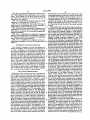
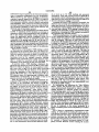
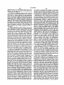
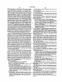
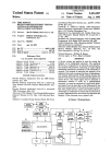
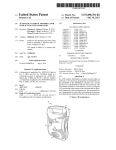
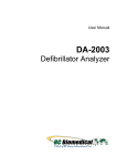
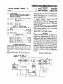
US005233986A
United States Patent [191
[11] Patent Number:
[45] Date of Patent:
Robson
[54] TIME DOMAIN
REFLECTOMETER-INTEGRITY TESTING
SYSTEM AND METHOD FOR MEDICAL
DEVICE ELECTRODE
[75] Inventor:
Jack R. Robson, Beech Grove, Ind.
[73] Assignee: Random Technologies, Inc.,
Related US. Application Data
Continuation-impart of Ser. No. 866,850, Apr. 10,
[63]
1992.
[51]
Int. Cl.5 ........................................... .. A61N 1/362
[52]
US. Cl. ........................................ .. 607/4; 607/27;
[58]
Field of Search ................................ .. 128/419.046
607/29
[56]
References Cited
U.S. PATENT DOCUMENTS
3,922,914 12/1975
4,466,288 8/1984
4,786,857 11/1988
4,843,234 7/1989
4,893,895 l/l990
Fuchs .............................. .. 73/290 R
Grynberg et a1. .................. .. 73/654
Mohr et a1. ........ ..
324/585 BO
Berthold et al. .............. .. 250/227
Berthold et a1. ................ .. 350/96
4,960,989 l0/_1990 Liebenrood et a1.
5,033,826’ 7/1991
Cordis Corporation 1986 “What Do These Pacers Have
in Common?”
Tektronix 1520C Metallic Time Domain Re?ectometer
Operator Manual May 1990.
Genesis TM Cardiac Pacing System Model 285 Techni
cal
Manual,
Pacesetter
#9190420-001.
Indianapolis, Ind.
[21] Appl. No.: 971,415
[22] Filed:
Nov. 4, 1992
250/227
Kozner .............................. .. 350/355
OTHER PUBLICATIONS
Tektronix 1520C Metallic Time Domain Re?ectometer
Service Manual Tektronix, Inc., Jul. 1991 pp. 5-1 to
5-11.
Quantum ®II—Intermedics ® Cardiac Pulse Generator
Physician’s Manual Models 253-25 and 254-30, Jan.
1990.
5,233,986
Aug. 10, 1993
Systems,
Inc.
Ventak ® PAICD TM Model 1600 Physician’s Manual
Automatic Implantables Cardioverter-De?ator 1991.
Hewlett-Packard Application Note 1962 “TDR Funda
mentals” Apr. 1988.
Hewlett-Packard Application Note 62-1 “Improving
Time Domain Network Analysis Measurements" Apr.
1988.
Hewlett-Packard Application Note 62-3 “Advanced
TDR Techniques”May 1990.
Primary Examiner-William E. Kamm
Attorney, Agent, or Firm-Baker & Daniels
[57]
ABSTRACT
A device and method for testing the integrity of an
electrode/wire, such as a pacemaker electrode, and
electrical wires connected thereto has a receptacle for
an electrode and includes a time domain re?ectometer
comprising an output signal mechanism operatively
connected to the electrode receptacle. The method of
analyzing the integrity of an electrode comprises the
steps of generating a time domain re?ectometer (TDR)
reading (output signal) from the electrode, and trans
mitting the signal to an output device. The output signal
may be analyzed to determined whether it varies by a
predetermined threshold, or it may be displayed so that
differences in the electrical characteristics of the elec
trode may be identi?ed. The present invention allows a
cardiologist or technician to ensure that the electrode is
properly engaged and to determine the integrity of the
electrode.
Pacesetter® Technical Manual-APSII Model 3000
Programmed with Model 3030 Function Pak, 1988.
WAPD
ANTBHA
mm
ma
23 Claims, 8 Drawing Sheets '
27
20
(
2a
)
12
2
masrm
m
m
necavaa
x)
"T5
mr
m
cavern.
oecuxron
13
1
a
oumrr
senor:
vouwz
2;
“M
[mm ]- 1,'\
as
)
+ 14
‘5
PULSE
.
m
"u
m
—>|3+
:wu,
mcwm'“
roemumn
eoumot
SYSTBI
,
~24
run
we
Am
com-not
l
i
'xwi
1985
.
“Z5
16
\17
U.S. P81181111
‘ Aug. 10, 1993
Sheet 5 of 8
0wW2|ECm<.w
wowhe.
(‘'1
wit.
EBwE<Fm
JL
8-.wow
wow
US. Patent
Aug. 10, 1993
Sheet 6 of 8
5,233,986
Na
m
1
1_
memawomaE
JN
JN
FP
Fmw‘
x
m.
539>.5
Eu
<mm.\d
_
9.2
8?5.
F
Nu
\/\
5& >mwt<
\L
_
50:
moh$.wS3Q9EmK‘zo W.UN?U: $5m
50E
moBz
,
8
,
US. Patent
Aug. 10, 1993
Sheet 7 of 8
’\/R2
\m \
5,233,986
\DISTANCE(M)
164
.55
K
/
1J1
(\ \ $19 0
DD46159
153
171
J
1 SWHO ) BDNVLSISHH
D1
15 V/
US. Patent
Aug. 10, 1993
Sheet 8 of 8
/
15A2-\v6910m
map
haw
5,233,986
1
5,233,986
2
uses paddles for de?brillation and patient cables for
TIME DOMAIN REFLECI‘OMETER-INTEGRITY I
monitoring ECG. A combination pacemaker and de?b
TESTING SYSTEM AND METHOD FOR MEDICAL
DEVICE ELECTRODE
brillator, available from ZMI Corporation of Woburn,
CROSS REFERENCE TO RELATED
and gel electrodes for pacing and for monitoring ECG
rillator such as the Zoll PD TM 1200 Pacemaker/De?
Mass., uses paddles or gel electrodes for de?brillation
APPLICATIONS
This is a continuation-in-part of application Ser. No.
signals. In all instances, the integrity of the de?brillator,
patient cable, or electrode is of utmost importance for
the proper operation of the external device.
07/866,850 ?led Apr. 10, 1992.
Presently, most portable pacemakers and defibrilla
FIELD OF THE INVENTION
This invention relates to a device, system and method
used in medical testing, and, in particular, to a technique
for testing the integrity of an electrode or cable (or
combination thereof) through which electrical signals,
such a heart pacing pulses, pass.
tors are periodically checked by hospital staff to deter
mine only whether the most basic functionality exists.
For example, a nurse may check such a unit to deter
mine whether it is plugged in, whether the proper dis
15 play appears when the unit is switched on, and whether
an appropriate quantity of ancillary supplies, such as
pacing pads, are readily available. However, other as
pects of the system do not lend themselves to being
readily checked. For example, many connectors be
provide assistance in the performance of various physi 20 tween the cables, leads, electrodes or pads of such sys
ological functions for an individual experiencing diffi
tems may become loose or bent, resulting in a poor or
BACKGROUND OF THE INVENTION
A number of medical devices are available which
culties. Some of these devices are implanted within the
open circuit. For such systems, there may be no appar
patient’s body while others are external and are typi
ent indication that the equipment is faulty, causing the
cally utilized under temporary or emergency situations.
defective equipment to be used on patients in critical
Whether residing inside or outside of the patient’s body, 25
condition. The only way to detect such an equipment
many devices include an electrode or cable connected
failure is for an astute medical technician to notice that
to the patient for the performance of a physiological
function or for the receipt of information from the pa
tient. Cardiac pacemakers, de?brillators, the Jarvis
all of the patients on which the defective equipment had
been recently used had died, and to have the equipment
heart and insulin pumps are a few examples of devices 30 thoroughly inspected by an advanced medical techni
which may be implanted within the patient’s body.
Some external devices, such as the Code Master De
External devices also include cardiac pacemakers and
?brillators
and the 2011 PD TM 1200 Pacemaker/De?
de?brillators and ECG monitors and other diagnostic
brillator, provide information to the operator or techni
equipment.
cian.
'
External pacemakers, de?brillators and the like are 35 cian regarding the “integrity" of the electrode. Speci?
cally, these systems provide a wanting when a complete
usually portable devices which are battery-powered
and capable of being recharged. The device’s portabil
ity is important because it is typically used in emergency
circuit is not provided. A complete circuit is one in
which there is current flow between the electrodes and
there are no severe discontinuities in the electrodes.
situations or as a temporary resolution to a patient’s
problems before a more permanent solution can be ren 40 Thus, the electrodes must be place against a patient’s
body to complete an electrical circuit in order to deter
mine whether a break exists in the cables, electrodes or
the connectors of either. Because the cables or elec
trodes must contact the patient before a test may be
external pacemaker may be used to provide assistance
to a patient who has not yet had an internal pacemaker 45 performed does not allow a fault in the system to be
identi?ed until the system must be used. Furthermore,
implanted or to provide pacing while the patient is in
because time is of the essence when the device is utilized
surgery to implant or replace an implantable pace
maker.
on a patient, it is desirable to provide an integrity testing
system for the electrodes or cables connected to such
To provide signals to the medical electrodes, or to
receive signals from the patient as is necessary for moni 50 external devices which does not require that the patient
toring, diagnostic or other functions of the device, ca
be connected to the electrodes or cables so that the
bles, electrodes or wires extend from the device to the
cables or electrodes may be tested on a routine basis. In
patient. For example, the Medtronic Model 5345 Tem
addition, it is desirable to provide a system that not only
porary Pulse Generator, available from Medtronic, Inc.
indicates whether there is an open circuit in a medical
of Minneapolis, Minn., is a temporary pacemaker such 55 electrical system, but location of the open circuit, e.g.
as may be used by a patient prior to implanting a perma
whether the break occurs where the cables plug into the
nent pacemaker. A patient cable is connected to the
pulse generating unit, the connector between the cables
device and unipolar or bipolar pacing leads contacting
and the pacing pads, or in the middle of the wires of any
the patient are connected to the patient cable. The Med
of the cables.
tronic model 5311 pacing system analyzer is used to test
Many of the electrodes used with these external de
dered. For example, de?brillators may be carried in an
ambulance or used in hospital emergency rooms to
revive a patient or to restore a normal heart rhythm. An
sensing and pacing thresholds of heart electrodes. The
Code Master De?brillators, available from Hewlett
Packard of Andover, Mass., provide the capabilities of
de?brillation and ECG monitoring. Both integral de?b
rillator paddles and optional gel electrodes may be used
with the device to accomplish these functions. Similarly
the Lifepak® 6 Cardiac Care System, available from
Physio-Control @ Corporation of Redmond, Wash,
vices are disposable. A sterilized-package containing the
electrodes is opened just prior to use. Thus, it is also
desirable to provide an electrode integrity testing sys
tem which is time efficient so as to avoid delaying the
65
provision of the assistance necessary. Furthermore,
because physicians will often be utilizing an integrity
testing system under stressful circumstances, it must be
easy to use and the results of the test must lead to quick
3
5,233,986
interpretation of the integrity of the electrodes or ca
bles.
It is also possible for a problem to occur with the
integrity of the cables or electrodes during their use.
For example, leads may become disconnected from the
patient or from the device or the cable to which the lead
is connected. Therefore, it is desirable to provide an
integrity testing system which can be operated during
the device’s operation and which does not interfere
4
mined threshold, or it may be compared to a previously
generated signal from the electrode so that differences
in the electrical characteristics of the electrode may be
identi?ed. The invention allows a cardiologist or tech
nician to ensure that the electrode is properly implanted
and to non-invasively determine the integrity of the
electrode over a patient’s life.
It is desirable to provide a method and device using
time domain re?ectometry to determine the integrity of
with the device’s other functions.
electrodes or cables connected to an external device to
Time domain re?ectometers, such as the 1502C Me
thereby alert the cardiologist or the technician of a
tallic Time Domain Re?ectometer manufactured by
potential or existing problem associated with the elec
Tektronix, Inc. of Beaverton, Oreg., are used to test the
trode or cable. As indicated above, time domain re?ec
integrity of cable such as co-axial cables. For such in
tometry may be used with both unipolar or bipolar
tegrity testing, time domain reflectometers send electri
electrodes. The velocity of propagation of any elec
cal pulses down the cable and detect any re?ections
trode is necessary for time domain re?ectometry mea
may by any discontinuities in the cable. Speci?cally,
surements. Such a parameter could be stored in the
time domain re?ectometers send out successive pulses
device.
and measure the respective re?ected pulses at times
It is also desirable to provide a method of analyzing
corresponding to points along the cable. Measurements 20 the integrity of the electrode or cable connected to the
are provided in terms of voltage versus time which can
external device. Such analysis could be completed in
then be converted to resistance over the length of the
within the device. Of course, to be used in conjunction
cable. Time domain re?ectometers can locate shorts,
with the portable devices, the integrity testing system
opens, defects in the shield of the cable, foreign sub
stances in the cable, kinks, and more. Generally, only 25 must be able to be integrated within the device and must
not consume a great deal of power.
one parameter is required for the proper operation of
the time domain re?ectometer in determining the integ
OBJECTS OF THE INVENTION
rity of a cable. That parameter is the velocity of propa
Accordingly, it is one object of the present invention
gation or the speed of the signal down the cable which
varies for different cable dielectric materials. Time do 30 is to provide a method and apparatus for testing the
integrity of cables, leads and/or electrodes connected to
main re?ectometers may operate on either a closed or
external medical devices, such as de?brillators, tempo
an open circuit. For an open circuit the signal continues
rary pacemakers or pacing system analyzers, to thereby
to be re?ected from the wire and returns to the instru
alert the physician or a technician of potential for exist
ment. In general, variations in the resistance measured
ing
problems associated with the electrode or cable that
by the time domain re?ectometer indicates a fault such 35
may be detrimental to the patient.
as a bad connection, the stripping of insulation, pressure
It is another object of the present invention to pro
on the cable, or a break in the cable.
vide a method for testing the integrity of such cables
Time domain re?ectometry has been used for a vari
and/or electrodes which does not require that the elec
ety of applications. In U.S. Pat. No. 4,466,288, time
domain re?ectometry is used to evaluate vibrations. 40 trode be in contact with a patient during such testing
The level of ?uid in a vessel may be determined by time
domain re?ectometry as disclosed in US. Pat. No.
3,922,914. Also, the constituents of a multi-phased ?uid
system have been evaluated as disclosed in U.S. Pat.
No. 4,786,857.
In addition, time domain re?ectometry has been used
for optical systems as well. For example, optical time
and therefore may be performed on a routine basis.
It is yet another object of the present invention to
provide a testing system which is easy to use and time
ef?cient to avoid any delay in the operation of the medi
45 cal device’s normal functions.
It is still another object of the present invention to
provide an integrity testing system which does interfere
with the normal operation of the medical device, may
domain re?ectometers, such as that disclosed in U.S.
Pat. No. 4,960,989, may be used to determine the tip
be integrated into the medical device and does not con
location of a consumable electrode within an electric
sume a great deal of power to operate.
furnace as disclosed in U.S. Pat. No. 4,843,234. Simi
BRIEF DESCRIPTION OF THE DRAWINGS
FIG. 1 shows a block diagram of one embodiment of
Pat. No. 5,033,826 to determine which surface of a
photographic lens is impairing transmissivity.
a device of the present invention when used in connec
U.S. patent application Ser. No. 07/866,850, ?led 55 tion with a programmable cardiac pacemaker.
larly, optical time domain re?ectometry is used in U.S.
Apr. 10, 1992, discloses an integrity testing system for
FIG. 2 a representative computer touch screen user
implantable electrodes such as may be utilized with
interface for con?guring and testing an implantable
implanted pacemakers or de?brillators. The electrical
electrode according to the invention.
device disclosed in U.S. patent application Ser. No.
FIG. 3 is a representative computer screen list win
07/866,850 has a receptacle for an electrode and in 60 dow displaying an index of previous TDR readings
cludes a time domain reflectometer comprising an out
which have been stored in the device.
put signal mechanism operatively connected to the
FIG. 4 is a representative computer screen list win
electrode receptacle. The method of analyzing the in
dow displaying a partial index of electrode manufactur
tegrity of an implanted electrode comprises the steps of
ers and models, one of which may be selected to pro
generating a time domain re?ectometer (TDR) reading 65 vide a set of default electrode, sampling and display
(output signal) from the electrode, and transmitting the
options for a particular electrode.
signal to an output device. The output signal may be
FIG. Sis a representative graphically displayed base
analyzed to determine whether it varies by a predeter
line TDR reading for an electrode in good condition.
5
5,233,986
FIG. 6 is a representative graphically displayed base
line TDR reading having superimposed over it a more
recent TDR reading for the same electrode showing
that a break has occurred in the electrode and that the
electrode is now defective.
FIG. 7 is a representative graphically displayed TDR
reading for an electrode have a short in it.
FIG. 8 is a representative time graph showing the
trailing end of a stimulating pulse on the electrode, a
TDR incident pulse, and re?ective pulse.
6
speci?ed after the pacemaker has been implanted. These
operating parameters are stored in random access mem
ory (RAM) 22, while the control program is stored in
read only memory (ROM) 21. Reprogramming is ac
complished through the use of an external system pro
grammer 28 having an RF transceiver wand 27, al
though a convention serial data port with lead connec
tors extending through the skin of the patient may also
be used.
10
The invention also includes time domain re?ectome
FIG. 9 shows a block representative diagram of one
embodiment of the device of the present invention
when used in connection with a portable, external de?
ter (TDR) I/O control 23, which includes the circuitry
necessary to generate a TDR pulse on the electrodes
and to detect the resulting voltage. A TDR applies a
narrow pulse of current (typically by a tunnel diode) to
the electrode and monitors the resulting reflected volt
brillator/pacemaker.
FIG. 10 is a representative graphically displayed
baseline TDR reading and a corresponding representa
age on the electrode over a period of time. A stored
tive diagram a patient cable connected to an electrode,
both of which are in good condition.
reflected voltage waveform comprises a raw TDR
reading. If the electrode has a known propagation ve
FIG. 11 is a representative computer screen of a
locity (Vp), the time delay to a particular re?ection may
de?brillator/pacemaker in which the patient cable is 20 be interpreted in distance from the pulse generator. This
defective.
would include the pacemaker’s internal wiring to the
pacing electrode connectors, the electrical connection
SUMMARY OF THE INVENTION
between the connectors and the pacing electrode, and
The invention comprises a device and method for
the entire length of the pacing electrode, terminating in
testing the integrity of an electrode. The electrical de 25 the portion placed in heart tissue. The amplitude of the
vice has a receptacle for an electrode and includes a
re?ected voltage is a function of the electrode impe
dance and the applied pulse, and therefore can be inter
preted in dB, or in rho, which is a function of impe
dance. Circuitry for time domain re?ectometers is well
known and, in isolation, do not form the present inven
time domain re?ectometer comprising an output signal
mechanism operatively connected to the electrode re
ceptacle. The method of analyzing the integrity of an
electrode comprises the steps of generating a time do
main re?ectometer (TDR) reading (output signal) from
tion. In general, a TDR comprises an I/O controller, a
the electrode, and transmitting the signal to an output
device. The output signal may be analyzed to deter
mined whether it varies by a predetermined threshold,
digital timebase, an analog timebase, and a pulse genera
tor. As described further below and shown in FIG. 8,
cian to ensure that the electrode is properly engaged
and to determine the integrity of the electrode.
storing of the TDR signal until the amount time speci
?ed by the TDR base time signal has elapsed after the
generation of a TDR incident pulse. At a speci?c time,
the TDR generates a short, square output pulse. After a
or it may be displayed so that differences in the electri 35 predetermined amount of time has passed (the TDR
cal characteristics of the electrode may be identi?ed.
base time), the pulse as re?ected back by the electrode
The present invention allows a cardiologist or techni
is monitored. This comprises means for deferring the
DETAILED DESCRIPTION
Referring to FIG. 1, there is shown a representative
block diagram of one embodiment of the present inven
as determined by the digital timebase, a portion or
“slice” of the re?ected wave is stored in an analog
timebase. This value is then converted to a digital value
by an analog to digital converter and stored in memory.
tion. In this embodiment, the invention is located in an
implantable multi-programmable pacemaker, which
45
The pulse generating-wave storing process is repeated,
includes logic and control unit 11 (which includes a
CPU and appropriate software to carry out the func
tions described herein), rate limit section 12, and output
tion an when a portion of the re?ected wave is stored is
section/voltage multiplier 13. Conventional microcir
cuitry, and preferably, an application speci?c integrated
re?ected wave to be stored. After a suf?cient number of
circuit, is used to package the TDR and other compo
nents in the implantable case. The pacemaker is de
signed to provide periodic pulse to two implantable
pacing electrodes through electrode receiving means,
except that the time period between the pulse genera
increased slightly, causing a different “slice" of the
50
samples (e.g., 256) have been collected, a compilation of
the stored waveform reading (a “TDR reading”) pro
vides a view of the entire re?ected wave. A representa
tive TDR pulse may comprise a 300 mV amplitude into
a 50 ohm load, with a 25 microsecond pulse duration,
namely connectors 14 and 15, and 16 and 17 respec 55 and the re?ected rise may be detected in less than 200
tively. However, the invention may also be used with a
picoseconds. To test for an open circuit, the system may
device connected to a single electrode. Connected to
merely measure the time between the incident pulse and
logic and control unit 11 is a telemetry system com
the beginning of the re?ected waveform.
prised of telemetry transmitter 18 and program receiver
In general, the present invention operates in the fol
19, both of which on connected to common antenna 20. 60 lowing manner. Logic and control 11 is designed to
The telemetry system allows the pacemaker to be inter
periodically send pacing signals via output line 24 to
rogated to determine its operating conditions after it has
output section/voltage multiplier 13. Logic and control
been implanted, and also allows the pacemaker to be
section 11 is programmed to cause output section/volt
reprogrammed without surgery. For example, the de
age multiplier to generate cardiac stimulating pulses of
vice can be reprogrammed to generate stimulating 65 predetermined amplitude, duration and frequency ac
pulses on the pacing electrode at set rate, or at a varying
cording to parameters stored in RAM 22. A typical
rate depending on cardiac activity. Other parameters,
cardiac pacemaker generates stimulating pulses at fre
such as the pulse width and pulse amplitude can also be
quencies of 0.5 to 3 per second, at amplitudes from 2.5
7
5,233,986
V to 8.5 V, and at durations of 0.15 to 2.3 milliseconds.
Accordingly there is a substantial time gap of at least
300 milliseconds between pulses. As a complete TDR
8
played on the screen as shown in FIG. 4, displaying a
list of electrode manufacturers and model numbers. The
physician may repeatedly depress the down arrow until
the electrode to be implanted is highlighted, then de
pulse and re?ection reading time can be accomplished
with a pulse repetition rate of 200 microseconds, it is
press the Select option 50 on the touch screen. This will
possible to take an entire set of 256 readings in well
under 60 milliseconds. Thus a complete TDR reading
close the display window, and cause the Electrode,
Sampling and Display options to be set to the default
values recorded in the database for the particular elec
can be generated between the stimulating pulses period
ically provided to the pacing electrode. However, it is
trode. While in this window (or any other window
also within the scope of the invention to space out the
which may be opened) at any time prior to depressing
TDR pulses between multiple stimulating pulses.
the Select option 50, the physician may depress the
Prior to implantation of the device in body, the de
vice will be programmed with various default parame
ters. Conventional pacemakers are programmed, for
Escape 47 portion on the screen, which will close the
window and cause the display to revert to its previous
status. A representative window and set of electrode
default information values is shown in FIG. 1. Should
example to specify the stimulating pulse repetition rate,
pulse amplitude, positive and negative sensitivities and
the physician desire to change any of the default values,
the physician may repeatedly depress the down arrow
until the value to be changed is highlighted. The physi
cian may then depress the left 48 and/or right 49 ar
control mode. Prior to implantation, one or more pac
ing electrodes will be selected and connected to pacing
leads 14, 15 and 16, 17 of the pacemaker. Each model of
electrode has its own characteristics, including a textual 20 rows, which will cause the highlighted values to be
model number, polarity, number of ?laments, electrical
decremented or incremented, respectively.
length, physical length, VP and source resistance. Rep
After the physician has speci?ed the desired elec
resentative electrode parameters to assist in taking later
trode con?guration values, the physician may store
TDR readings, are shown as electrode menu options 40
them in the pacemaker so that they do not have to be
in FIG. 2. In addition, each electrode will ideally have 25 reprogrammed each time a TDR reading is taken. This
a set of default sampling 41 and display 42 options.
is done by depressing the up or down arrows until the
Preferably, the electrode parameters, sampling and dis
play options may be speci?ed by the electrode manufac
“Store Con?guration to Pacemaker” option is selected.
The Select button is then depressed, which causes all of
the displayed electrode information to be transmitted to
the pacemaker by RF transceiver 27 and stored in RAM
turer and used to set default values in the pacemaker
prior to implantation. Storing these parameters into the
pacemaker is accomplished using conventional teleme
22. If the pacemaker provides means for connecting to
try programming equipment with appropriate software
a second electrode, such as for multiple leads, or in
cludes two leads for single electrode (i.e. a pulse and a
to carry out the functions described herein.
To program'the default electrode, sampling and dis
play options into the pacemaker, external programmer
ground) then the pacemaker RAM 22 may be con?g
35 ured with suf?cient memory to store a separate setting
28 is ?rst turned on, and the telemetry head of wand
antenna 27 is positioned over the pacemaker. The telem
etry head generates a magnetic ?eld which activates
reed switch 25 inside the pacemaker. This switch causes
logic and control unit 11 to activate program receiver 40
for each electrode or lead. In addition, pulse selector
will include switch means for selecting whether the
time domain re?ectometer is operably connected to the
means for connecting the ?rst implantable electrode or
the means for connecting to the second implantable
electrode. The location for each storage will be desig
nated by the “Electrode No.” option in FIG. 2. If a
19 and to receive instructions from programmer 28. In
one embodiment of the invention, programmer 28 has a
touch screen and various options are selected by touch
pacemaker having capability for storing only one set of
ing the indicated portion of the screen. The physician
will initially step through the prompts displayed on
45 store electrode settings for an electrode other than no.
electrode readings receives an instruction and data to
programmer 28 to transmit the desired pacemaker set
1, the number information may be ignored and the val
ues replaced by the received values.
ties and mode) into the pacemaker. The physician may
After this information has been speci?ed, and prior to
then select a TDR option on programmer 28, which
implantation, the physician may take an initial TDR
will cause programmer 28 permit the TDR parameters 50 reading. This is done by using the up and down arrows
to be speci?ed and displayed, such as through the TDR
to highlight the “Obtain TDR Reading” option, the
options screen shown in FIG. 2.
depressing the Select option 50 on the touch screen.
The physician will initially wish to specify the default
This action causes programmer 28 to transmit a com
TDR values to be stored in the pacemaker. Ideally,
mand to the pacemaker commanding the pacemaker to
programmer 28 will include a database of electrode
take a TDR reading according to the parameters stored
manufacturers and models, with default electrode, sam
in RAM 22.
pling and display options for each electrode model. The
When the pacemaker receives an instruction to take a
database may be periodically updated by programmer
TDR reading, the pacemaker waits until no stimulating
28 manufacturer via a floppy disk with information
pulse is present on the electrode. Referring to FIG. 8,
concerning new electrodes on the market. When the 60 normally, if stimulating pulses are being generated on a
physician ?rst enters the TDR menu, the top “Read
periodic basis, logic and control unit 11 will wait until
tings (e.g. stimulation rate, pulse amplitudes, sensitivi
Con?guration for Pacemaker” option will be high
the trailing edge of stimulating pulse 101 has been gen
lighted in reverse video. To select a default electrode
erated. Because stimulating pulse 101 may cause noise
con?guration from the database, the physician presses
to be present on the electrode for a short time period
down arrow 43 to cause the “Select Con?guration from 65 after the pulse is generated, no action is taken during the
Electrode Database” option to be highlighted. The
physician then depresses the Select button 50 on the
time previously speci?ed as TDR Blanking Interval
103. This system comprises means for deferring genera
screen. This causes an overlapping window to be dis
tion of the TDR incident pulse until the amount of time
9
5,233,986
speci?ed by the TDR blanking interval has elapsed
after the transmission of a stimulating pulse on the elec
trode, or the detection of an identi?ed physiological
event. For stimulating pulse electrodes, this allows volt
age on the electrode to completely drain until the TDR
reading process begins. Also, some sensing electrodes,
such as those used to monitor heart activity, may have
a rhythmic voltage on them generated by an internal
organ. Such electrodes are used, for example, to moni
tor cardiac activity, and logic and control unite 11 sec
tion of the pacemaker is capable of determining, at any
point in time, the status of the rhythmic activity. For
such electrodes, it is desirable to time each TDR read
ing to begin at the same time in the rhythmic cycle so
that each TDR reading is taken at the same time of the
10
to-digital converter in TDR I/O 23, and then transmit
ted to logic and control section 11 for storage in output
device, such as RAM 22. After a predetermined amount
of time, such as 200 microseconds from the initiation of
the ?rst incident pulse, TDR I/O 23 generates second
TDR pulse 108. The above process is repeated numer
ous (e.g. 256) times, except the time at which an analog
voltage reading is stored in the analog timebase is incre
mented slightly with each cycle. As a result, RAM 22
has stored in it a raw TDR reading representing‘the
re?ected waveform.
After the TDR reading has been generated, logic and
control section 11 sends a signal to pulse selector 26
causing the electrode connectors 14,15 and/or 16,17 to
be electrically reconnected to the output section 13, and
electrically disconnected from TDR I/O 23. The isola
tion of TDR I/O 23 from output section 13 by pulse
rhythmic cycle, and therefore less subject to noise. For
a cardiac sensing electrode, TDR blanking interval 103
may begin after completing of physiological event such
selector 26 guards against any damage to the circuitry
as the atrial beat, as sensed by logic and control 11, and
of TDR I/O 23 from stimulating pulses generated by
last for 300 milliseconds. After the 300 millisecond 20 output section 13. Thereafter, the generation of stimu
blanking interval, the TDR reading (or readings) may
lating pulses may resume.
be made, as further described below, and the readings
If the number of readings averaged parameter is
may be completed before the ventricular beat begins.
greater than one, then the TDR reading process may be
This method, in combination of the minimal current
repeated, either immediately, if the time until the next
needed to generate a TDR incident pulse, minimizes the 25 stimulating pulse to be generated is sufficiently long, or
likelihood of causing an irregular heartbeat. This system
else after the next stimulating pulse is generated. Taking
constitutes an anti-coincidence detector adapted to pre
multiple TDR readings and averaging them reduces
vent a stimulating signal or physiological event from
any noise that may be inherent in a single reading. For
interfering with the incident pulse signal generated by
averaged readings, instead of storing the each set of
the time domain re?ectometer and its reflected wave. 30 individual TDR waveform readings to the same RAM
After the TDR blanking interval has passed, logic
and control system 11 sends an signal to pulse selector
) unit 26, which causes the electrode leads to be switched
from an electrical connection with output section 13 to
address, the digital values may be added to the previ
ously stored values. After the total number of TDR
readings speci?ed by the “No. of Readings Averaged”
parameter has been completed, the each sum may be
the TDR I/O and control section 23. (During normal 35 divided by the number of readings comprising the sum
pacemaker operation, TDR I/O and control 23 is insu
to obtain a composite reading, namely the average.
lated by pulse selector 26 from the stimulating pulses, to
Alternatively, it is envisioned that merely the raw TDR
minimize the possibility that the relatively large cur
readings may be transmitted to programmer 28 as de
rents and voltages of the stimulating pulses will harm
scribed below, and programmer 28 perform the averag
the TDR circuitry.) Logic and control 11 then sends a 40 ing of the readings.
signal to TDR I/O and control 23, which comprises
It will be appreciated from the description of the
means for transmitting an electrical signal to the elec
foregoing embodiment that the time domain re?ectorm
trode receiving means, commanding the TDR to gener
eter, i.e. the system for generating incident pulses and
ate an incident pulse 104 (see FIG. 8) on the selected
storing the reflected wave form, comprises a logic and
electrode lead.
45 control system as is already found in conventional pace
In one embodiment of the invention, logic and con
trol section 11 may include in the signal it sends to TDR
I/O 23 a signal representing a impedance through
which the TDR pulse should be sent. Ideally, the impe
dance equals the impedance of the electrode. Accord
ingly, TDR I/O 23 may include an internal array of
source resistors of various impedances through which
an incident pulse may be transmitted, and be connected
makers, as well as TDR I/O circuitry.
.
After the raw or composite TDR reading has been
stored in RAM 22, logic and control section 11 trans
mits the stored raw or composite waveform through
TDR reading output signal means, such as transceiver
means comprised of telemetry transmitter 18 and an
tenna 20, to wand 27 of programmer 28. In addition, in
the preferred embodiment, logic and control section 11,
to a multiplexor to select which resistor the pulse
will also transmit to programmer 28, the stored sam
should be transmitted. This provides a preferred TDR 55 pling values used to take the TDR reading to program
re?ection waveform.
mer 28. This transmission assures that the correct pa
After generation of incident pulse 104, TDR I/O
rameter values may be displayed in association with the
waits the amount of time represented by TDR Base time
TDR reading. Programmer 28 then displays the re
105. Normally, this amount of time will be selected to
ceived TDR reading in graphical form on a monitor (in
represent the amount of time it will take for a re?ected
graphical display window 411) or a printer, or both.
pulse to be detected by TDR I/O 23, and may be on the
Preferably, programmer 28 includes a Print button
order of l-l0,000 nanoseconds, depending on the elec
which when depressed, causes the displayed graph, and
trical characteristics and length of the electrode. After
current con?guration information to be printed. A rep
TDR Base Time 105 passes, the TDR stores analog
resentative TDR waveform for a working electrode is
voltage detected 106 on the electrode in an analog time 65 shown in FIG. 7. The horizontal axis represents the
base. Voltage 106 represents only a small portion of the
entire re?ected waveform 107. This analog voltage
value is then converted to digital format by an analog
time, or sequential samples of the TDR reading, which
can be directly converted into electrode distance if the
VP of the electrode is known. As discussed above, this
11
5,233,986
information may be supplied by the electrode manufac
turer or manually programmed into the programmer.
With a known VP, the vertical gridlines, or divisions,
represent a speci?c length from the TDR I/O output to
the end of the electrode. The vertical axis of the wave
form represents millirhos, which is directly convertible
into impedance. Thus, a rise in the waveform represents
increased resistance along the electrode, while a fall in
the waveform represents a short circuit between the
electrode and the pacemaker ground.
Accordingly, for the representative waveform shown
in FIG. 7, waveform rise 52 represents an increase in
resistance, which in this representative case, is attributa
ble to the internal pacemaker wiring connection be
12
ity to store up to 512 TDR readings and associated
information. Logic and control 11 stores in RAM 22 an
incremental counter indicating the total number of read
ings that have been stored in RAM 22 and the address of
the next subsequent reading to be stored.
Assuming the initial TDR reading is acceptable, the
physician may proceed with implantation of the pace
maker and electrode. Following implantation, but prior
to closing the surgical incision in the patient, the physi
l0 cian may take a second TDR reading to ensure that no
damage to the pacemaker or electrode occurred during
implantation. Assuming the TDR reading is acceptable,
the physician may close the incision.
Following implantation, the patient can be expected
tween the application speci?c integrated circuit on 15 to have numerous follow-up visits with the physician,
which pacemaker circuitry is connected and the wires
during which the integrity of the implanted electrode
connected to the pacing leads 14, 15, and 16, and 17.
may be evaluated. This may be done using the same
Second waveform rise 53 is attributable to the intercon
programmer 28 described above. After the programmer
nection between electrode receptacle and the electrode
is turned on, wand 27 is positioned over the patient’s
plug. Thereafter, the waveform is flat, indicating a con
pacemaker, and the TDR option is selected, the screen
stant impedance throughout the length of the electrode,
shown in FIG. 2 may appear. The physician choose to
with no breaks or shorts.
?rst retrieve a copy of the archived TDR reading from
FIG. 5 shows a representative TDR reading in which
when the electrode was ?rst implanted. This may be
the electrode has a partial short and is in need of re
done by using up 44 and down 43 arrows to highlight
placement. Such a short may be caused, for example, by 25 the “Review Archived TDR Readings” option, and
defective insulation between the leads of a bipolar elec
depressing Select. This will cause programmer 28 to
trode, or by the exterior insulation of the electrode
send a signal to the pacemaker instructing logic and
becoming worn by, for example, excessive rubbing
control section 11 to transmit the archive number, date,
against a bone, pacemaker case or other structure. The
comment and physician portions of each archived TDR
short is evident by waveform fall 60, indicating the
reading to the programmer. An archived TDR display
impedance of the electrode at that point has fallen.
window, as shown in FIG. 3 is then displayed. Using up
At anytime while a TDR Reading is displayed, the
44 and down 43 arrows, the physician may highlight an
physician may depress the cursor left 45 or cursor right
archived TDR reading, which will normally be the
46 arrows below the display to cause graphical cursor
baseline reading or ?rst reading archived after implanta
48 to move left or right. At the point where cursor 48 35 tion. Depressing the Select portion of the screen causes
intersects waveform 49, the distance of the electrode
programmer 28 close the widow and to command the
circuit and impedance of the waveform are shown in
displays 54 and 55. Thus, cursor 48 and displays 54 and
55 comprise means for superimposing a distance scale
measurement corresponding to the length of the im
pacemaker to transmit the selected archived TDR read
ing (including the electrode, sampling and display op
tions) to the programmer, where they are displayed.
The physician may then depress the up arrow to high
light the “Obtain TDR Reading” menu option, then
planted electrode on the graphical display.
After the physician has obtained and displayed the
composite TDR reading, the reading may be transmit
press Select 50. This will cause a TDR reading to be
programmer 28, such as “Pre-implant readings w/Tech
nitronics 1000”, and in which the physician may enter
graphical display. Speci?cally, minimum warning line
generated as described above, and superimposed over
ted back to the pacemaker and stored in RAM 22,
the archived TDR reading.
which comprises means for storing multiple TDR out 45 By highlighting and adjusting the “Max Millirho
put signals. As shown in FIG. 2, this may be done by
Alarm” option, the physician may specify a millirho
depressing the down arrow until the “Archive Current
value (predetermined threshold) by which, if a TDR
TDR Reading in Pacemaker” menu option is high
reading deviates in a relevant portion, an indicating
lighted. The Select button is then depressed. This causes
output warning signal, such as a ?ashing light, buzzer,
programmer 28 display a dialogue box on the screen in
or “DEFECTIVE” screen display is generated. High
which the physician may type a short descriptive sum
and low limits from the electrode portion of the display
mary of the reading using a keyboard connected to
waveform may be represented as horizontal lines on the
64 and maximum warning line 65 as shown in FIG. 67
his or her name. After this option information has been 55 de?ne the boundaries in which the entire electrode
entered, the Select button is again depressed, causing
portion of the waveform is expected to fall. If a wave
programmer 28 to transmit the TDR waveform, along
with the Sampling Options, Display Options and textual
form deviates from these limits, DEFECTIVE legend
66 may be displayed on the screen, preferably in a
information (including the date, which comprises a
highly contrasting color and accompanied by an audible
means for associating each stored output signal with a
alarm.
time reference indicating when the output signal is gen
FIG. 6 shows a representative superimposed TDR
reading, in which archived reading 61 shows an elec
trode in good condition, while current reading 62 shows
that the electrode has broken. Speci?cally, reading 62
erated) through wand antenna 27 to antenna 20 of the
pacemaker, accompanied by a command instructing the
pacemaker logic and control 11 to store the information
in RAM 22. This stored reading may be used as a base 65 includes waveform rise 63, indicating that the impe
line TDR reading against which future TDR readings
dance of the electrode has risen. This may be caused by,
may be compared to assist in evaluating electrode integ
for example, a ?lament becoming cracked or com
rity. In one embodiment, RAM 22 has sufficient capac
pletely severed. Because current reading 62 exceeds
13
5,233,986
maximum alarm level 65, DEFECTIVE legend 66 is
displayed on the screen, alerting the physician that the
electrode may be defective.
The Current Con?guration parameters 40, 41 and 42
shown in FIG. 2, as mentioned above, may be adjusted.
With regard to Display Options 42, these parameters
effect how a particular TDR reading is displayed on the ‘
screen. In particular, different electrodes from different
manufacturers and for different purposes will generate
14
rity number or pacemaker serial number, to distinguish
between stored readings from different patients. Also,
graphical display of programmer 28 may include means
for displaying the amplitude differential between the
incident pulse and a selected portion of a TDR reading.
Referring now to FIG. 9, there is shown a representa
tive block diagram of one embodiment of the device of
the present invention when used in connection with a
portable, external de?brillator/pacemaker. The de?bril
TDR readings have different impedance baselines and 10 lator/pacemaker includes a central processing unit
lengths. In order to scale a TDR reading on the graphi
(CPU) 120 (which includes appropriate memory and
cal display, the Vertical and Horizontal reference points
software to carry out the functions described herein),
and scales may be adjusted. These values will also be
stored along with an archived TDR reading so that
when the reading is retrieved, it will be initially dis
played using the same viewing parameters as when it
was stored.
It will be appreciated to those of skill in the art that
power supply 121, battery 122, charging circuitry 123
and display 124. The device is powered by battery 122
and may be recharged by charger circuitry 123. Display
124 may comprise a computer screen, LCD display,
plotter, or other such similar device. In this embodi
ment, three primary functions are provided by the de?
may changes could be made in the foregoing represen
brillator/pacemaker. First, the device may serve as a
tative embodiment without departing from the spirit 20 de?brillator through de?brillator circuitry 125, which
and scope of the invention. For example, the present
is responsible for the delivery of energy to de?brillator
invention may be used with virtually any type of medi
paddles connector 126 connected to de?brillator cir
cal electrode, such as ventricular, rate sensing, mor
cuitry 125. The second function of the de?brillator/
phology, high voltage, mapping, sensor, temporary,
pacemaker is as a pacemaker. Pacing circuitry 127,
ablation and angio/artheretomy electrodes. The inven 25 connected to pacer output connector 128, delivers
tion may also be used in connection with wires used in
pulses to electrodes (see FIG. 11) connected to pacer
connection with devices such as insulin pumps, and
output connector 128. Third, the de?brillator/
such wires are within the scope of the term “electrode”
pacemaker includes the capability to monitor the ECG
as used herein and in the claims. In addition, in instances
signal of a patient through ECG circuitry 129 con
where a tube or stint is implanted in a patient, a tube 30 nected to ECG connector 130. In addition to these
con?gured with an embedded electrical conductor run
conventional functions of the de?brillator/pacemaker,
ning the length of the tube and connectable to a TDR,
and which will break if the tube breaks, is also included
the device also includes TDR circuitry 131 connected
to CPU 120 and to de?brillator paddles connector 126,
within the de?nition of an electrode as used herein.
pacer output connector 128 and ECG connector 130.
Electrodes as used herein also include electrical con 35
As discussed in detail for the embodiment of the in
ductors that are external to a patient used to send or
vention illustrated in FIGS. 1-8, TDR circuitry 131
receive electrical signals, such as, for example, ECG
includes the circuitry necessary to generate a TDR
electrodes, or external pacemaker or de?brillator leads.
pulse and to detect the resulting voltage. Such a pulse
It will also be appreciated that although the in the
embodiment described above a TDR reading is output
may be caused to travel to individual de?brillator pad
dles connector 126 and the paddles connected thereto,
through RAM and an RF antenna, other transceiver or
output means are within the spirit and scope of the
or through an electrode connected to pacer output
connector 128 or ECG connector 130. Circuitry for
invention. For example, virtually any other electromag
time domain re?ectometers is well known and, in isola
tion, does not form the present invention.
desired frequency, including optical frequencies, or 45 FIG. 10 is a representative graphically displayed
wire leads may be used to transmit a TDR reading.
baseline TDR reading and a corresponding representa
Moreover, the TDR reading described above is ob
tive diagram of a patient cable connected to an elec
tained by generating multiple incident pulses and stor
trode tip, both of which are in good condition. Such a
ing a small portion of each reflected pulse. It is contem
con?guration may be such as connected to pacer output
plated that with the development of faster electronic 50 connector 128 (see FIG. 9) wherein a patient cable is
and CPU circuitry, that a TDR reading may possibly be
connected to the pacer output connector and an elec
generated by storing the reflected wave from a single
trode tip is connected to the patient cable. In the display
incident pulse, and such systems included within the
of resistance versus distance over which the TDR pulse
de?nition of a TDR. It will also be appreciated that in
travels, the distance from the origin of the graph to
the embodiment described above, a user-selected num 55 distance D1 represents the internal circuitry of medical
ber of multiple raw TDR readings may be averaged to
device 171 and the resistance of internal circuitry 151 is
produce a composite reading to eliminate noise associ
shown to be substantially constant. First connector 191,
ated with individual readings. The averaging function
connecting patient cable 192 to device 171 is repre
could easily be transferred from the internal implantable
sented by ?rst connector resistance curve 153 between
device to external programmer 28. Moreover, other 60 distances D1 and D2. A rise in resistance occurs over
manipulations of raw TDR readings, such as by averag
the distance comprising ?rst connector 191. From the
ing multiple readings, would not necessarily alter their
beginning of patient cable 192 to the end of the patient
de?nition as being a TDR reading. Other functions
cable 192, represented by distance D2 to D3, patient
contemplated to be performed by the pacemaker could
cable resistance 155 is shown. Patient cable resistance
also be performed by external programmer 28. For 65 155 is substantially constant and is expected to be be
example, the storage of TDR readings could be per
tween minimum patient cable resistance value R1 and
formed on external programmer 28, and optionally, may
maximum patient cable resistance value R2. Should
be indexed by a unique key, such as patient social secu
patient cable resistance 155 achieve a value outside of
netic wave communication means may be used, at any
15
5,233,986
16
predetermined thresholds, namely the minimum and
maximum values R1 and R2, respectively, it is known
function 200 may not be necessary should the ECG
that there is a short, break or other discontinuity in
patient cable 192. Second connector 193 connects pa
tors and cables/wires as are used for the pacing function
monitoring function operate through the same connec
of de?brillator/pacemaker 181.
In FIG. 11, second graphical display section 190 is
tient cable 192 to electrode tip 194 and is represented by
the distance D3 to D4. In the range between distance
D3 and distance D4, second connector resistance 159
rises as indicated. From the beginning of the electrode
194 to the end of the electrode tip 194, represented by
distance D4 to D5, electrode resistance 161 is substan
tially constant and should reside within the prede?ned
threshold range between minimum electrode resistance
value R3 to maximum electrode resistance value R4. At
the termination of electrode 194 at a distance D5, the
value of resistance rises as shown if electrode 194 is not
highlighted indicating de?brillator/pacemaker 181 is in
its pacing con?guration. Along patient cable 192 is a
marked or highlighted trouble area 198. Also at the top
right of the display is message 199, BREAK IN CA
BLE, which is also highlighted or marked. This simple
display, which may be accompanied by an audible
alarm, immediately informs the physician or technician
that there is a discontinuity of signi?cance in patient
cable 192 which requires replacement of patient cable
192 for the proper operation of de?brillator/pacemaker
connected to a patient, i.e., if there is an open circuit. In
one embodiment, the upper and lower resistance thresh
olds are plus or minus ten percent (10%) of the expected
181.
It will be appreciated by those of skill in the art that
there may be discontinuities or breaks in either ?rst
resistance at any distance along the completed circuit.
electrode 194 or second electrode 195 in this con?gura
It will be appreciated by those of skill in the art that 20 tion. One of the advantages of the use of TDR technol
much of the analysis discussed herein with regard to the
ogy is that more than one problem can be identi?ed and
embodiment of the invention illustrated in FIGS. 1-8
displayed to the physician or technician. Moreover, the
may be used to determine whether patient cable 192 and
system may be easily tested by, for example, intention
electrode 194 or connectors 191 and 193 are within
ally unplugging an electrode from the system and deter
desired resistance range or, more speci?cally, whether 25 mining whether a BREAK IN CABLE message is dis
played.
there is a problem of signi?cance with patient cable 192,
electrode tip 194 or connectors 191 and 193. However,
it is desirable to provide a simplistic method of display
ing the information to a technician or a physician. Re
membering that time is of the essence in the use of the
external devices, the display should be such that a prob
It will also be appreciated by those with skill in the
art that TDR technology may be used in connection
with a variety of types of wires, cables, or electrodes
extending from such a medical device. The technology
need not be limited to a particular type of cabling, nor
should the requirement of the device to use a successive
connections of various cable types preclude the use of
lem is quickly discemable by the operator.
Referring now to FIG. 11, there is shown a represen
tative computer screen of an external, portable, tempo
the technology to determine defects in the attached
rary defibrillator/pacemaker in which the patient cable 35 cabling. Thus, the term “electrode” as used in the
is defective. The display is divided into three sections.
claims may encompass de?brillator cables, patient ca
First display section 180 illustrates de?brillator/
bles, electrodes or other wires, or to any combination
pacemaker 181 having ?rst and second de?brillator
thereof, extending from such a medical device. Also,
cables 184, 185 connected to ?rst and second to paddles
186, 187 respectively and also connected at ?rst and
second de?brillator connectors 182, 183 of de?bril
the term “medical device” as used in the claims may
encompass any electrical device used in the medical
profession wherein an “electrode,” as defined herein, is
connected to the device.
lator/pacemaker 181. Second graphical section 190
illustrates the con?guration of de?brillator/pacemaker
It will be further appreciated that the TDR technol
181 when used in the pacing mode. Patient cable 192 is
ogy is not limited to a single wire connected to a medi
connected to de?brillator/pacemaker 181 at cable con 45 cal device. Rather, the technology may be used for any
nector 191 (which may be equivalent to pacer output
connector 128 shown in FIG. 9). At the other end of
patient cable 192 is connector 193 to which ?rst and
second pacing electrodes 194, 195 are connected.
Thereafter, electrodes 194, 195 are connected to ?rst
and all wires, cables, sensors or pads extending from the
medical device. In this manner, the technician may
check the system prior to its use to insure that the com
ponents are all operational. Accordingly, as used herein
and in the claims, the term “electrode” includes all of
the components used to carry an electrical signal from
the instrumentation to the patient and back, even where
and second pacing electrode pads 196, 197, respec
tively, which are placed on the patient. It should be
noted that pacing electrodes 194, 195 need not be con
nected to pacing electrodes pads 196, 197 for integrity
testing of electrodes 194, 195 to be performed.
Third graphical display section 200 shows de?bril
lator/pacemaker 181 when used is connection with ?rst
and second monitoring electrodes 204, 205 for the pur
pose of monitoring ECG signals. In the ECG monitor
ing con?guration, patient cable 202 is connected to
this consists of discrete pieces electrically connected
together.
55
It will further be appreciated that the system of the
present invention can not only test for electrode integ
rity prior to use, but during operation of the medical
device. Such a feature is desirable because with the
frantic pace at which medical technicians operate dur
60 ing a medical emergency, it is possible for electrical
de?brillator/pacemaker 181 by connector 201 and to
cables to become inadvertently pulled and thereby re
monitoring electrodes 204, 205 at its other end. As dis
duce the integrity of the electrical connections between
cussed above, monitoring electrodes 204, 205 may be
them. Thus, in one embodiment of the invention, CPU
connected to monitoring electrode pads 206, 207, re
120 is programmed through conventional software to
spectively, which are then in turn placed on the patient. 65 monitor a patients heartbeat through ECG connector
It will be appreciated by those of skill in the art that the
130. As the heartbeat occurs on a periodic basis, CPU
display actions are dependent on the device and connec
120 can detect point in time when it is between heart
tors employed. For example, third graphical display
beats, and therefore little or no electrical activity on
17
5,233,986
ECG electrodes. At such a point, CPU causes a signal
to be transmitted to ECG 129 to cause its electrical
connection to ECG connectors to be disabled, and a
signal to be transmitted to TDR 131, to cause its output
to _be connected to ECG connector 130. A TDR read
18
2. The device of claim 1 wherein the device com
prises a pacemaker.
3. The device of claim 1 wherein the device com
prises a de?brillator.
4. The device of claim 1 wherein the output signal of
the means comprises a TDR reading from the time
domain re?ectometer.
ing is then taken by TDR 131. CPU 120 then transmits
a signal to TDR 131 causing it to electrically disconnect
from ECG connector 130, and to ECG 129, causing it
5. The device of claim 1, wherein the output signal
to reconnect to ECG connector 130. The combination
of these components act as an anticoincidence detector
means comprises means for graphically displaying a
TDR output signal.
to eliminate the possibility of a TDR reading being
6. The device of claim 1, further comprising:
taken at the same time a signal is transmitted on the
means for storing a reference TDR signal representa
tive of a TDR signal from a working electrode
connected to the electrode receiving means,
means for comparing a TDR output signal to a stored
ECG electrodes to monitor the heartbeat. Due to the
short time period needed to take a TDR reading, there
is no appreciable interruption in ECG readings. How
15
ever, the TDR reading can be stored in memory and
reference TDR signal,
compared to a reference TDR signal for the ECG con
nectors, as described above. If the comparison indicates
that a break or short in a ECG electrode has occurred,
means for indicating whether the TDR output signal
varies from the stored reference TDR signal by a
a graphical display showing the location of the break 20
7. The device of claim 6 wherein the means for indi
and an audible alarm are generated. It will also be ap
preciated that the above procedure can also be em
ployed for the de?brillator output and pacing outputs,
prede?ned threshold.
cating comprises a graphical display of an electrode.
8. The device of claim 7 further comprising means for
graphically displaying the relative point on the graphi
cally displayed electrode where the TDR output signals
As it is contemplated that the TDR circuitry may be 25 varies from the stored reference TDR signal by the
reduced to a small and inexpensive application specific
prede?ned threshold.
integrated circuit, it is also within the spirit and scope of
9. The device of claim 1, further comprising means
so the integrity of the entire system may be tested.
the invention that separate TDR’s be provided for each
electrode circuit, instead of providing a single TDR
for receiving at least one additional electrode, the time
domain re?ectometer means being operatively con
with switch means which may be used to connect the 30 nected to the at least one additional electrode receiving
TDR to different electrodes. It is also contemplated that
means such that at a time domain reflectometer pulse
different types of TDR readings may be taken for differ
may be transmitted to the at least one additional elec
ent types of electrodes. For example, for longer elec
trode receiving means.
trodes, it may be desirable to take a TDR reading con
10. The device of claim 9, further comprising at least
sisting of 1,024 time divisions instead of 256 divisions. In 35 one ECG reading electrode connected to at least one of
addition, the gain and resolution at which TDR reading
the electrode receiving means.
may be graphically displayed may very depending on
11. The device of claim 9, further comprising means
the electrode being tested. It is contemplated that such
for automatically causing a TDR reading to be taken on
parameters may be separately stored for each electrode
each electrode receiving means.
in a system, and automatically recalled and used to take 40
12. A method of analyzing the integrity of a ?rst
a particular TDR reading.
medical electrode for transmitting an electrical signal,
It will further be appreciated that the system of the
comprising the steps of:
_
present invention may include an integral graphical
providing means for transmitting an electrical signal
printer and a test mode switch. When the test mode
on the ?rst electrode, the transmitting means being
switch is activated, CPU 120 automatically cycles 45
through each electrode in the system and conducts an
integrity test, the results of which may be printed out
with a date and time stamp. Such a system allows its
integrity to be checked on a routine basis and before a
medical emergency. In addition, ‘the printout can pro 50
vide written documentation that the system was
checked at the designated time.
What is claimed is:
1. An electrical medical device comprising:
means for receiving a ?rst electrode,
means for transmitting a ?rst electrical signal to the
capable of being selectively enabled and disabled,
providing a time domain re?ectometer (TDR) opera
tively connected to the first electrode,
disabling the transmission of electrical signals on the
?rst electrode,
generating a ?rst TDR reading from the ?rst elec
trode and outputting the TDR reading,
reenabling the transmission of electrical signals on the
?rst electrode.
13. The method of claim 12 wherein the means for
transmitting comprises a means for transmitting pace- -
maker pulses.
electrode receiving means,
14. The method of claim 12 wherein the means for
time domain re?ectometer means operatively con
transmitting comprises a means for transmitting a de?b
nected to the electrode receiving means such that
rillator pulse.
at a time domain re?ectometer pulse may be trans 60
15. The method of claim 12 wherein the means for
mitted to the electrode receiving means, the time
transmitting comprises a means for transmitting an
domain re?ectometer means comprising output
signal means, and
anti-coincidence means preventing a time domain
ECG reading signal.
16. The method of claim 12, wherein the disabling of
the transmission of electrical signals on the ?rst elec
re?ectometer pulse from being transmitted to the 65 trode occurs based on the timing of heartbeats of a
patient to whom the electrode is connected.
signal is being transmitted to the electrode receiv
17. The method of claim 12, further comprising the
ing means.
steps of:
electrode receiving means when a ?rst electrical
19
5,233,986
storing a reference TDR signal representative of a
20
providing at least One Second @cdica] eleclfofie, and
TDR signal from a working electrode connected to
the electrode receiving means,
comparing the outputted TDR signal to the stored
5
reference TDR signal, and
Provldmg means for opcratlvely comlcctmg the
TDR to the at least one second medical electrode
such that a time domain re?ectometer pulse may be
transmitted thereto, and
providing means for selecting which of the electrodes
indicating whether the outputted TDR signal varies
the TDR may be operatively connected to.
from the stored reference TDR signal by a prede21' The method of claim 20, wherein the means for
?ned threshold
selecting comprises automatic means for automatically
18. The method of claim 17 wherein the indicating 10 causing a TDR reading to be taken on each medical
step includes graphically displaying an electrode.
electrode
19. The method of claim 17 wherein the indicating
22- The mcthod of claim 12, fu?hcl' comprising the
step further includes, if the outputted TDR signal varies
§tcp of graphically displaying the outputted TDR read‘
from the stored reference TDR signal by a prede?ned
mg‘
threshold, graphically displaying the relative point on 15
the gra hically dis_played electrode where the TDR
.
. .
23' 1216 method of 01mm 12’ further compnsmg the
steps 0"
selecting a portion
of the generated TDR reading,
output signals varies from the stored reference TDR
and
signal by the Prede?ned thl'eshold-
graphically displaying the selected portion of the
20. The method of claim 12, further comprising the 20
steps of:
TDR reading.
‘
25
35
45
SO
55
65
"
*
'
‘