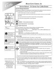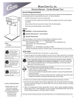
1
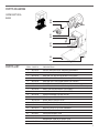
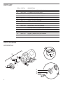
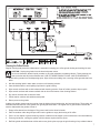
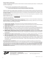
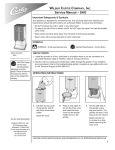
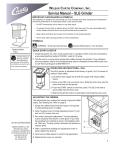
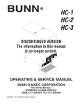
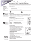
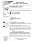
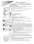
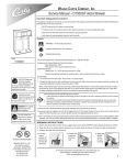
Wilbur Curtis Company, Inc.
Service Manual – Digital Interlock Grinders
Important Safeguards & Symbols
This appliance is designed for commercial use. Any servicing other than cleaning and
maintenance should be performed by an authorized Wilbur Curtis service technician.
• Do NOT immerse the unit in water or any other liquid
• To reduce the risk of fire or electric shock, do NOT open top panel. No user serviceable
parts inside.
• Keep hands and other items away from hot parts of unit during operation.
• Never clean with scouring powders or harsh chemicals.
SYMBOLS
WARNINGS – To help avoid personal injury Models Included
ILGD
CAUTION: Please use
this setup procedure
before attempting to use
this grinder. Failure to follow the
instructions can result in injury or
the voiding of the warranty.
Important Notes/Cautions – from the factory
SETUP STEPS
1.Install the grinder on a firm, level base in a location where it can be connected to a
grounded electrical outlet of 120VAC, rated at 15 amps minimum.
2.Test the unit by running some whole bean coffee through the grinder. If any problems
are encountered, refer to the troubleshooting section complete at www.wilburcurtis.com
or call Technical Support at 800-995-0417.
3. Interlock Connection: If hooking up the brewer and grinder for the Interlock option,
locate the jack on back of the brewer marked CLASS 2 WIRING. Plug in the Interlock
cable from the grinder into this jack on the brewer.
OPERATING INSTRUCTIONS
1. Lift open the top cover of the grinder and fill with fresh whole
bean coffee. Close the cover.
2. Position an empty coffee container onto the brew deck.
WARNING TO AVOID
SCALDING, Remove
the brew cone carefully.
The brew cone contains hot
coffee grounds. Wait until the
brewer indicates that the brew is
finished before removing.
3. Place a new paper filter into the brew cone.
4. Insert the brew cone into the basket holder arms on the
grinder.
5. On the grinder control panel, press the desired grind size/brew
volume button; SMALL, MEDIUM or LARGE.
6. Make sure the motor comes to a stop before removing the
brew cone.
ISO 9001:2008 REGISTERED
WILBUR CURTIS CO., INC.
6913 West Acco Street
Montebello, CA 90640-5403
For the latest information go to
www.wilburcurtis.com
Tel: 800-421-6150
Fax: 323-837-2410
7. For Interlock brewers: The brew selection is “Locked” into the
brewer, indicated by a flashing LED next to the corresponding
brew button.
8. Transfer the filled brew cone to the brewer and press the desired brew button. The brew cycle is complete when the brew
light stops flashing.
ADJUSTING THE GRINDING BURRS
1. Empty the hopper of coffee beans. Run the grinder for a short time to clear
grinding burrs of coffee.
2. Open the housing cover (10) to locate the adjustment screw (8) and lock nut
(7). With a wrench, loosen the lock nut.
3. Turn the adjustment screw clockwise for a finer grind. Turn the screw counter clockwise for a more coarse grind. With the motor running, pour coffee
beans into the hopper and turn the screw to make the adjustment. If you
hear the grinding burrs starting to touch, immediately, back off 1/8th turn.
4. When the desired grind texture is satisfactory, hold the adjustment screw in
place with the screwdriver and tighten the locknut.
5. Grind some coffee beans to confirm the adjustment.
6. Replace front cover on machine.
*This adjustment may change the amount of ground coffee dispensed.
CHANGING A BROKEN SHEAR DISK
1.Unplug the power cord.
2.Empty the hopper of beans.
3.Take out the thumb screws (9) to remove the housing cover (10).
4.Pull out the grinding burr/feed worm assembly (3). The mating alf of the grinding burr set remains within the housing.
5.Separate the shear cap (6) and shear drive (4). The snapped shear disk (5) should fall from the shear drive.
6.Inspect and brush out the housing (1).. Especially look for anything that could have broken the shear disk.
7.Insert the feed worm and grinding burr onto the motor shaft.
8.Push the shear drive through the burr/feed worm assembly and align it with the tongue on the motor shaft.
9.Rotate the burr/feed worm assembly to align the slot with narrow slot on shear drive.
10. Insert a new shear disk into the slot. Cover with the shear cap.
11. Replace the grind cap and two thumb screws.
ROUGH-IN DRAWING
9.88”
(25.1 cm)
1.75”
(4.4 cm)
21.63”
(54.9 cm)
14.50”
29.50”
(36.8 cm)
(74.9 cm)
6.50”
(16.5 cm)
2
7.50”
(19.1 cm)
3.00”
(7.6 cm)
10.00”
(25.4 cm)
PROGRAMMING THE ILGD GRINDER
Your grinder has been adjusted at the time of manufacture to provide satisfactory performance in most situations. In the
event that you would like to vary the settings the grinder can be reprogrammed. Both grinders are programmed identically.
1. Place a paper filter beneath the grinder spout to catch coffee as it is ground.
2. Turn off the unit at the front panel, ON/OFF button.
3. Press and hold one of the grind buttons.
4. Press and release the ON/OFF button. Continue holding the grind button.
5. In the red window, the grind time on the button pressed will appear. Continue
to hold and the time digits will start at 00 and increase. Release the button
to set the new time. The table (left)can be used as a guide to estimate the
amount of ground coffee you dispense with the chosen setting.
6. Wait for the motor to completely stop (10 seconds). To set and exit, press and
release any other grind button.
7. Repeat the above steps to reset any other grind button.
Seconds
Ounces
Seconds
Ounces
4
1.3
15
4.5
5
1.5
20
6.2
6
1.8
25
7.6
7
2.0
30
8.8
8
2.5
35
10.0
10
3.0
40
11.8
12
3.7
45
13.5
Time settings in this table are only approximate. Amounts will vary with grind texture and specific coffee bean. Weigh your output, then
make adjustments as necessary.
TROUBLE- SHOOTING
SYMPTOM: MOTOR DOES NOT RUN
GUIDE
This appliance is
designed for commercial use. Any
servicing other than
cleaning and maintenance
should be performed by an
authorized Wilbur Curtis service center.
POSSIBLE CAUSE
SOLUTION
1. Circuit breaker may be tripped.Grinder has a circuit breaker behind machine. Push in reset
button. You should hear a “click”.
2. Electrical cord may not be making contact.
Push plug into outlet.
3. Electrical outlet may not have power.
With voltmeter, determine if there is power at outlet.
SYMPTOM: MOTOR RUNS BUT NO COFFEE COMES OUT
POSSIBLE CAUSE
SOLUTION
4. Shear disk may have broken.
Change the shear disk (see page 2 for directions).
5. Funnel to grind housing may be jammed.
Cut off power to machine. Empty the hopper of beans.
Clean where the hopper funnels into the grind housing.
SYMPTOM: GROUND COFFEE TEXTURE TOO COARSE OR POOR QUALITY
POSSIBLE CAUSE
SOLUTION
6.Grinding burrs may be worn.
Readjust the grind (see page 2).
7. Housing cover may not be on straight or not seating correctly.
Pull off the cover and clean the mounting surfaces.
Reassemble the housing.
3
PARTS DIAGRAM
HOPPER & TOP COVER
1
2
3
4
5
6
7
11
8
10
9
CENTER COVER & GEAR MOTOR
16
12
13
19
14
18
15
17
4
PARTS DIAGRAM
GRIND MOTOR &
BASE
26
20
21
25
27
24
22
23
PARTS LIST
ITEM
PART NºDESCRIPTION
1
WC-9118
COVER, HOPPER DUAL GRINDER ASSEMBLY
2
WC-9131
WINDOW, ACRYLIC DUAL GRINDER
3
WC-9143
SPACER, 5/8” AGITATION WHEEL (OPTIONAL)
4
WC-9160
WHEEL, GRINDER AGITATION CCG (OPTIONAL)
5
WC-9144
SPACER, 9/32” AGITATION WHEEL (OPTIONAL)
6
WC-9132
DIVIDER, DUAL HOPPER, SS
6A
WC-9188
DIVIDER, W/HOLE ILG-11/DHG-11 (AS SHOWN, OPTIONAL)
7
WC-9142
SHAFT AGITATION WHEEL (OPTIONAL)
8
WC-9116
HOPPER ASSEMBLY, DUAL GRINDERS
9
WC-9158
AUGER ASSEMBLY DHG/ILG/ILGD
10
WC-9183
BEARING, AUGER BRASS
11
WC-91013
WRAP, DUAL HOPPER ILGD
12
WC-9130
FUNNEL, DHG/ILGD
13
WC-9134
SHIELD, HOUSING, ILGD/ILG/SHG/DHG
14
WC-9151*
MOTOR, GEAR 115V DUAL GRINDER
15
WC-1504
BREAKER, CIRCUIT 10A 120/250VAC
16
WC-689*
CONTROL BOARD, ILGD
17
WC-9126
GUIDE, SPOUT W/A
18
WC-39212
MEMBRANE CONTROL PANEL ILGD
19
WC-3796
LABEL, ADJUSTMENT INFORMATION
5
PARTS LIST
ITEM
PART Nº
DESCRIPTION
20
WC-9107-6*
DISK, SHEAR COFFEE GRINDER 6 PCS/PKG
21
WC-37283*
KIT, GRINDER CHUTE DHG/ILGD/SHG
22
WC-3503
LEG, 3/8”-16 STUD SCREW BUMPER
23
WC-3518
LEG, GLIDE 3/8”-16 STUD SCREW
24
WC-4813
SCREW, SHOULDER, 5/16 x 5/8
25
WC-9141
BASKET HOLDER ASSEMBLY
26
WC-9135*
MOTOR, SLICING GRINDER ASSEMBLY 120VAC SHG/DHG/ILGD
27
WC-9155
SPRING, BASKET HOLDER
28
WC-91024
SHEAR DRIVE COFFEE GRINDER
29
WC-91015
SCREW & THRUST PIN ADJUSTING ASSEMBLY
30
WC-91026
CAPACITOR, COFFEE GRINDER ASSEMBLY
31
WC-91050
BURR, COMPLETE SET SLICING
32
WC-91021
SPRING, TENSION COFFEE GRINDER
33
WC-91051
FEEDWORM, SLICING GSG
PARTS DIAGRAM
MOTOR DETAILS
26
28
20
21
30
29
31
32
33
6
Cleaning the Coffee Grinder
Regular cleaning and preventive maintenance is essential in keeping your coffee grinder looking and working like new.
CAUTION – Unplug the grinder from the electrical power source.
Do not use cleansers, bleach liquids, powders or any other substance containing chlorine. These products promote corrosion and will pit the stainless steel. USE OF THESE PRODUCTS WILL VOID THE WARRANTY.
1. Brush coffee grounds from the dispensing spout. Wipe off the surrounding area, removing coffee grounds that have
fallen.
2. Mix dish washing liquid in warm water to make a mild cleaning solution.
3. Care should be taken to avoid spilling liquid into the grind housing.
4. Wipe exterior surfaces with a cloth moistened with cleaning solution. Clean off coffee grounds, drips or spills.
5. Wipe exterior surfaces with a water soaked cloth to rinse off all traces of the cleaning solution.
6. Dry exterior surfaces with a clean soft cloth.
7. Polish exterior surfaces with stainless steel polish.
8. Return power to the grinder.
A tablet style grinder cleaner may be used to clean the inside of the grind housing, the burrs and chute. The product will
eliminate taste and odor left in the grinder from grinding flavored coffee. The regular use of grind cleaner reduces the
need to disassemble the grinder to clean it.
1. Empty coffee beans from the hopper. Plug power cord into the electrical outlet.
2. Place a container under the grind spout and run the grinder to empty the housing of all coffee.
3. Pour in or two capfuls of grinder cleaner granules or tablets into the hopper (use manufacturer’s recommendations).
4. Press a grind button, running the grinder until the cleaner empties from the spout.
5. Refill the grinder with whole bean coffee and run two grind cycles to purge the grind housing of any residual cleaner.
7
Product Warranty Information
The Wilbur Curtis Company certifies that its products are free from defects in material and workmanship under normal use. The following limited
warranties and conditions apply:
3 Years, Parts and Labor, from Original Date of Purchase on digital control boards.
2 Years, Parts, from Original Date of Purchase on all other electrical components, fittings and tubing.
1 Year, Labor, from Original Date of Purchase on all electrical components, fittings and tubing.
Additionally, the Wilbur Curtis Company warrants its Grinding Burrs for Forty (40) months from date of purchase or 40,000 pounds of coffee,
whichever comes first. Stainless Steel components are warranted for two (2) years from date of purchase against leaking or pitting and replacement parts are warranted for ninety (90) days from date of purchase or for the remainder of the limited warranty period of the equipment in which
the component is installed.
All in-warranty service calls must have prior authorization. For Authorization, call the Technical Support Department at 1-800-995-0417. Effective
date of this policy is April 1, 2003.
Additional conditions may apply. Go to www.wilburcurtis.com to view the full product warranty information.
CONDITIONS & EXCEPTIONS
The warranty covers original equipment at time of purchase only. The Wilbur Curtis Company, Inc., assumes no responsibility for substitute replacement parts installed on Curtis equipment that have not been purchased from the
Wilbur Curtis Company, Inc. The Wilbur Curtis Company will not accept any responsibility if the following conditions are not met. The warranty
does not cover and is void under the following circumstances:
1) Improper operation of equipment: The equipment must be used for its designed and intended purpose and function.
2) Improper installation of equipment: This equipment must be installed by a professional technician and must comply with all local electrical,
mechanical and plumbing codes.
3) Improper voltage: Equipment must be installed at the voltage stated on the serial plate supplied with this equipment.
4) Improper water supply: This includes, but is not limited to, excessive or low water pressure, and inadequate or fluctuating water flow rate.
5) Adjustments and cleaning: The resetting of safety thermostats and circuit breakers, programming and temperature adjustments are the
responsibility of the equipment owner. The owner is responsible for proper cleaning and regular maintenance of this equipment.
6) Damaged in transit: Equipment damaged in transit is the responsibility of the freight company and a claim should be made with the carrier.
7) Abuse or neglect (including failure to periodically clean or remove lime accumulations): Manufacturer is not responsible for variation
in equipment operation due to excessive lime or local water conditions. The equipment must be maintained according to the manufacturer’s
recommendations.
8) Replacement of items subject to normal use and wear: This shall include, but is not limited to, light bulbs, shear disks, “0” rings, gaskets,
silicone tube, canister assemblies, whipper chambers and plates, mixing bowls, agitation assemblies and whipper propellers.
9) Repairs and/or Replacements are subject to our decision that the workmanship or parts were faulty and the defects showed up under normal
use. All labor shall be performed during regular working hours. Overtime charges are the responsibility of the owner. Charges incurred by
delays, waiting time, or operating restrictions that hinder the service technician’s ability to perform service is the responsibility of the owner
of the equipment. This includes institutional and correctional facilities. The Wilbur Curtis Company will allow up to 100 miles, round trip, per
in-warranty service call.
RETURN MERCHANDISE AUTHORIZATION: All claims under this warranty must be submitted to the Wilbur Curtis Company Technical
Support Department prior to performing any repair work or return of this equipment to the factory. All returned equipment must be repackaged
properly in the original carton. No units will be accepted if they are damaged in transit due to improper packaging. NO UNITS OR PARTS WILL
BE ACCEPTED WITHOUT A RETURN MERCHANDISE AUTHORIZATION (RMA). RMA NUMBER MUST BE MARKED ON THE CARTON
OR SHIPPING LABEL. All in-warranty service calls must be performed by an authorized service agent. Call the Wilbur Curtis Technical Support Department to find an agent near you.
ECN 16063 . 8/7/[email protected] . rev D
1/22/[email protected] . ECN 15619 . rev C
6/24/[email protected] . ECN
15123
. CO., INC.
WILBUR
CURTIS
10/10/[email protected] . ecn
14475
. ear
10674
6913
Acco St.,
Montebello,
CA 90640-5403 USA
7/6/[email protected] . EDRPhone:
7842
800/421-6150
Fax: 323-837-2410
Technical Support Phone: 800/995-0417 (M-F 5:30A - 4:00P PST)
Web Site: www.wilburcurtis.com
8
E-Mail: [email protected]
8/2014 . F-3117-S . rev D