1
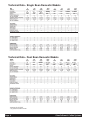
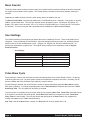
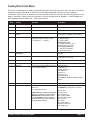
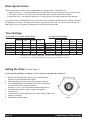
Grind’n Brew Coffee Systems®
Operation and Instruction Manual
for
Models: -11, -21, -10, -20 including H, HQ versions
TABLE
OF
C ONTENTS
Warning Labels . . . . . . . . . . . . . . . . . . . . . . . . . . . .3
Technical Data . . . . . . . . . . . . . . . . . . . . . . . . . . . . .4
Unit Installation . . . . . . . . . . . . . . . . . . . . . . . . . . . .5
Water Hook-up . . . . . . . . . . . . . . . . . . . . . . . . . . . . .5
Electrical Hook-up & Start-up Procedure . . . . . . . . .6
Operating the Touchpad . . . . . . . . . . . . . . . . . . . . .6
Brewing . . . . . . . . . . . . . . . . . . . . . . . . . . . . . . . . . .7
User Lockout . . . . . . . . . . . . . . . . . . . . . . . . . . . . . .7
Model Grind’n Brew-10H
Model Grind’n Brew-11H
Bean Counter . . . . . . . . . . . . . . . . . . . . . . . . . . . . .8
User Settings . . . . . . . . . . . . . . . . . . . . . . . . . . . . . .8
Pulse Brew Cycle . . . . . . . . . . . . . . . . . . . . . . . . . .8
User Menu . . . . . . . . . . . . . . . . . . . . . . . . . . . . . . . .9
Brew Volume Setting . . . . . . . . . . . . . . . . . . . . . . .10
System Restore Feature . . . . . . . . . . . . . . . . . . . .10
Factory/Field Test Menu . . . . . . . . . . . . . . . . . . . .11
Water System Errors . . . . . . . . . . . . . . . . . . . . . . .12
Timer Settings . . . . . . . . . . . . . . . . . . . . . . . . . . . .12
Setting the Grind . . . . . . . . . . . . . . . . . . . . . . . . . .12
Maintenance . . . . . . . . . . . . . . . . . . . . . . . . . . . . .13
Shear Plate Replacement . . . . . . . . . . . . . . . . . . .14
Troubleshooting Guide . . . . . . . . . . . . . . . . . . . . .15
Exploded Views . . . . . . . . . . . . . . . . . . . . . . . . . . .17
Model Grind’n Brew-20H
Model Grind’n Brew-21H
Wiring Diagrams . . . . . . . . . . . . . . . . . . . . . . . . . .22
Prior authorization must be obtained from
Grindmaster Corporation for all warranty claims.
Grindmaster Corporation
4003 Collins Lane
Louisville, KY 40245 USA
(502) 425-4776
(800) 695-4500
(800) 568-5715 (Technical Service Only)
FAX (502) 425-4664
www.grindmaster.com
© Grindmaster Corporation, 1997
PRINTED IN USA
Patents Pending
0307 Form # BW-350-13
Part #70661
Warning Labels
! WARNING:
USE ONLY ON A CIRCUIT THAT IS PROPERLY PROTECTED AND CAPABLE OF THE
RATED LOAD.
! WARNING:
ELECTRONICALLY GROUND THE CHASSIS.
! WARNING:
DO NOT DEFORM PLUG OR CORD.
! WARNING:
FOLLOW NATIONAL AND LOCAL ELECTRICAL CODES.
! WARNING:
WATER CONNECTIONS SHALL COMPLY WITH THE PLUMBING CODE OF BOCA & THE
FOOD SERVICE SANITATION MANUAL OF THE FDA
! WARNING:
DO NOT USE NEAR COMBUSTIBLES.
! WARNING:
FAILURE TO COMPLY RISKS PERSONAL INJURY, DAMAGE TO EQUIPMENT, FIRE OR
SHOCK HAZARD.
! WARNING:
READ THE ENTIRE OPERATING MANUAL INCLUDING THE LIMIT OF WARRANTY AND
LIABILITY BEFORE BUYING OR USING THIS PRODUCT.
! WARNING:
ALWAYS UNPLUG UNIT FROM POWER SUPPLY BEFORE SERVICING.
Grind’n Brew® Coffee Systems
Page 3
Technical Data - Single Bean Domestic Models
120
120
208/240
1710
1710
2674
208/240
120
120
208/240
208/240
3560
1810
1810
2749
3660
x
x
x
x
x
x
x
x
Technical Data - Dual Bean Domestic Models
Page 4
120
120
208/240
1710
1710
2674
208/240
3560
120
120
208/240
208/240
1810
1810
1810
1810
208
2749
3660
3660
Grind’n Brew® Coffee Systems
Unit Installation
IMPORTANT:This brewer should be installed by a knowledgeable and experienced commercial
equipment installer.
Brewer Contents
Your brewer package should include the following:
1 Grinderbrewer (either single or dual bean)
1 Operation and Instruction Manual (this manual)
1 Hose to 1/4" flare fitting (part # 61237)
Tools Required for Installation
#2 Phillips screwdriver
9/16" wrench
5/8" wrench
(or crescent wrench)
6" level
NOTE: Other tools may be needed depending on the type of water supply tubing and location.
1. Inspect unit to see if any damage occurred in shipment.
2. Position brewer on counter. Place on sturdy permanent counter top. If you have an airpot brewer, install the 4"
plastic legs (included) at the bottom of the brewer. Lean the brewer towards its side to expose screwholes underneath for legs. Adjust the leg height to suit the size of airpots you will use. IMPORTANT: Adjust the feet to
level the brewer. With bubble level, check to see that the brewer is level on countertop.
Water Hook-up (All Models)
(Refer to Figure A)
IMPORTANT: This equipment must be installed in compliance with applicable Federal, State and/or
Local plumbing codes having jurisdiction. Incoming water pressure should be greater
than 20 psi and not more than 100 psi.
1. The incoming water supply should have a shut-off valve connected in-line. The end should have a female 1/4"
flare fitting. Water supply should be a 1/4" I.D. dedicated line branched off a 1" or larger supply line.
2. Prior to installing the brewer, flush out the water line by running approximately 1 gal. of water into a pail.
This will insure no sediment from a new installation can get in the brewer.
3. Make sure your source water is turned off. Connect the water line’s 1/4" female flare fitting (1) to the 1/4" male fitting on the hose connector (2).
4. Make sure Grind’n Brew is unplugged. Connect the water line to the brewer with the hose connector (2).
5. Turn the water valve on, sending water to the brewer. If there are any leaks, tighten connections to stop leakage.
Figure A
Grind’n Brew® Coffee Systems
Page 5
Electrical Hook-up and Start-up Procedure (All Models)
IMPORTANT:
IMPORTANT:
IMPORTANT:
IMPORTANT:
Do not plug the unit in yet.
This equipment must be installed in compliance with applicable Federal, State and/or
Local electrical codes having jurisdiction. Do not use extension cords. Make sure that
the outlet the brewer plugs into is grounded.
Make sure that the Main Power Switch in the back of the unit is in the Off position before
plugging in the brewer.
Domestic Q models at 208/230V must have a 4 wire electrical connection. The circuit must
have 2 hots, 1 ground and 1 neutral wire. Failure to install with a 4 wire connection will void
the manufacturer’s warranty. 208/230 Volt Grind’n Brew units require a 20 Amp circuit.
1. Plug the brewer into an electrical outlet (or run power to unit for hardwire applications).
2. Make sure the brew basket is inserted in the brew rails.
3. Reach to the back of the brewer and press the white Main Power Switch to the On position. The front control lights
will go on, and water will enter the brewer. The tank will fill in 2-3 minutes from the moment the Main Power Switch is
turned on.
4. Once the tank is full, it will take 10-15 minutes to heat the water to the brewing temperature. (Cut that time in half for
the 230V “Q” models.) Once the Ready light is lit, you are ready to brew.
Operating the Touchpad
(Refer to Figure B)
1. To select the appropriate bean hopper, press the hopper (left) button until the desired indicator arrow is illuminated.
NOTE: This step only applies to dual bean hoppers.
2. To select a portion size, press the center of the Portion Size (middle) button until the half pot or full pot symbol
(depending on your need) is illuminated.
3. The Mode (right) button allows you to select either the “Brew Only”, “Grind Only” or “Grind and Brew” feature.
a) To grind only, press the center of the Mode (right) button until the grinder symbol is illuminated.
b) To brew only, press the center of the Mode (right) button until the coffee cup symbol is illuminated.
c) To grind and brew, press the Mode (right) button until both symbols are illuminated together.
Bean Selector
(Dual Bean Models Only)
Half or Full Pot
Figure B
(Dual Bean Model)
Grind only
Brew only
Grind and Brew Option
(Single Bean Model)
IMPORTANT: Brewers are factory set for throw weight and water portion. Please check that installation
is correct before making adjustment. No adjustments should be necessary for normal
installation.
Page 6
Grind’n Brew® Coffee Systems
Brewing
IMPORTANT:
Brewers are factory set for the correct grind and brew times for average situations. You
should not need to make adjustments in the field.
1.
2.
3.
4.
5.
Make sure that a new paper filter is in the brew basket and the brew basket is in place in the brewer.
Place beans in the hopper.
Choose to “Grind and Brew”. Press the far right touchpad so “Grind and Brew” lights are lit.
Choose the Portion Size. Press the middle touchpad until desired volume is lit.
Choose Decaf or Regular coffee (only applicable to dual bean Grind’n Brews). Press left touchpad.
Arrow will either point left or right for Decaf or Regular.
6. Place a decanter or airpot under the brew basket, depending on the model.
7. Press Start. You will see the coffee bean level go down slightly. You will hear the coffee grind. Coffee is automatically ground, portioned and placed in brew basket. Then ground coffee is automatically brewed. The Ready light
will now blink, indicating that grinding and brewing are in progress. This will take 3-4 minutes for a 1/2 gal. pot.
Portions are factory set. A stop function is added to the start switch. When this switch is depressed, it allows the
unit to stop during the selected grind, brew or grind and brew functions.
After brewing a pot, the tank must reheat. Reheat time is 5 1/2 - 8 minutes for 120V brewers and half that time
for 230V machines. Remember that the brewer will not function (although the grinder will) until the Ready light is
on, indicating that the water is hot enough to brew. A flashing green light indicates that the brewer is reheating or
that there is a cycle in progress. Do not remove the brew basket while the light is flashing. The brew basket
must be removed before a new brew can be initiated . This feature ensures that the operator discards the old
coffee grounds and installs a new coffee filter.
User Lockout
User Lockout is achieved via the position of the LOCK jumper on the board header. Locate the header on the board
(shown below) and place the jumper in the desired position. In the Locked position all menus in this document are
locked out, and the unit will only allow brewing or grinding functions. There are two versions of the header, 10 pin
and 2 pin. Both configurations are shown below.
10 Pin Version
Locked
1
User
Lockout
Jumper
LOCK
Unlocked
1
LOCK
2 Pin Version
Locked
LOCK
Unlocked
LOCK
User Lockout Jumper
Grind’n Brew® Coffee Systems
Page 7
Bean Counter
The built-in bean counter measures relative usage of its Grind’n Brew® machine by totaling the amount of seconds
the augers have fed beans into the grinder. This number directly correlates to the amount of beans used by the
machine.
Depending on model, the bean counter is either always shown or hidden to the user.
The Bean Counter Menu is accessed by holding the UP and DOWN keys for 5 seconds. If the counter is normally
hidden, it will be shown here. The user can reset the counter through this menu. Pressing the SET button will
display “REs” and the user can select “YEs” or “no” with the UP and DOWN keys. Pressing the SET key finalizes
the selection. This menu times out after 10 seconds and is disabled by the User Lockout Jumper.
User Settings
The Grind’n Brew® has several factory-set options that can be modified by the user. These are divided into two
categories: Universal Settings or Brew Settings. Universal Settings pertain to the whole unit, and Brew Settings
pertain to one of the four available brew cycles – (Regular Full, Regular Half, Decaf Full and Decaf Half). All
settings are retained during a power loss. The original factory settings can be restored by using the System
Restore Function.
User Settings
Universal Settings
Temperature Scale
Water Temperature
Low Temp No Brew Enable
Brew Settings x 4
Auger Time
Pulse Brew Pulses
Pulse Brew Pour Time
Pulse Brew Delay Time
Brew Time
Pulse Brew Cycle
Pulse Brewing is a feature that increases the control and performance of the Grind’n Brew® machine. By pulsing
water during the brew cycle, you allow greater contact time and better extraction of the coffee. Ultimately you will
achieve a bolder and more consistent cup of coffee by using this feature.
If pulse brewing is selected, the unit will brew the number of pulses identified by the Pulse Brew Pulses setting.
Each pulse is identical. It will begin by dumping water for the Pulse Brew Pour Time and then wait for the Pulse
Brew Delay Time. This will repeat until all pulses are finished.
Once the pulses are complete, the unit will pour water for the remaining Brew Time. Brew Time is the total amount
of time water is poured over the coffee grinds. Pulse Brew Pour Times are included in this total. Pulse Brew
Delay Times are not included. The cycle will always stop pouring once the Brew Time is met, regardless of
whether this happens in the middle of pulse brewing.
Drip Time is half of the Brew Time. However, the Drip Time will never be greater than 1:30.
Page 8
Grind’n Brew® Coffee Systems
User Menu
The User Menu is accessed by pressing the SET key on the display board. Navigation is accomplished by pressing
the UP, DOWN and SET keys. Feedback to the user is shown by the 3-digit numerical display.
The User Menu exits after a 1 minute timeout or all modes are stepped through. This menu is disabled by the User
Lockout Jumper.
Brew Settings - Brew Cycle Selection
There are four independent settings for brew cycles: Regular Full Brew, Regular Half Brew, Decaf Full Brew and
Decaf Half Brew. The User Menu adjusts settings for the brew cycle selected by the keypad. For instance, if
you want to change settings for Decaf Half brew then set the keypad to the Decaf Hopper and Half Brew Size
before entering the User Menu. The keypad settings cannot be changed while the User Menu is displayed.
User Menu Navigation
Advancing through the menu is done by pressing the SET Key. Each parameter is adjusted by pressing the UP
and DOWN keys. Pressing and holding the UP and DOWN keys will quickly scroll through settings. The table
below shows how to step through this menu.
Step Setting
1
Temperature Scale between
°F or °C
2
Water Temperature
setpoint in °F or °C
3
Show Auger Time
the amount of coffee
into the grinder
Set Auger Time
the amount of coffee
into the grinder
Show Brew Time
Total amount of pour
the brew cycle
Set Brew Time
Total amount of pour
the brew cycle
Show Pulse Brew
4
5
6
7
8
9
10
11
12
Display
Adjustments
Displays the current
selection. Factory default
is “°F”
Displays the current
selection. Factory default is
“195” in °F or “91” in °C.
“At”
“°F” or “°C”
“170” to “205” °F
“77” to “96” °C
None
beans fed
Displays the current
beans fed selection depending on Brew
Cycle
“br”
time for
“0.1” to “45.0” seconds
None
Displays the current
selection depending on Brew
Cycle
“P-b”
“0.01” to “6.00” in minutes.seconds
Pulse Brew Pulse Number
sets the number of pulses in
the brew cycle
Pulse Brew Pour Time
sets the amount of pour time in
each pulse
Pulse Brew Delay Time
sets the amount of delay time
between each pulse
Show Low Temp No Brew
Displays the current
selection depending on Brew
Cycle
Displays the current
selection depending on Brew
Cycle
Displays the current
selection depending on Brew
Cycle
“Ltn”
“OFF” to “10”
Set Low Temp No Brew
enable or disable
Displays the current
selection. Factory default
is “YES”
“OFF” or “ON”
time for
Grind’n Brew® Coffee Systems
None
“0.05” to “1.00” in
minutes.seconds
“0.05” to “1.00” in minutes.seconds
None
Page 9
Brew Volume Setting Menu
This feature sets the brew time based on water volume of a desired container. Before using this feature, remove the
brew basket, remove the spray head and place the desired container in place underneath the brewer.
The Brew Volume Setting Menu is started by selecting a brew cycle and holding in the START switch for 5
seconds. The display will show “Pro” at this time. Again press the START switch, and water will begin dispensing
into the container. The display shows a Brew Time count at this time. When satisfied with the water level, again
press the START switch. At this point the Brew Time flashes on the display for 20 seconds. Press the START
switch again within the 20 seconds to accept the new Brew Time. No changes will be made if the Brew Time is not
confirmed in this last step.
There are four independent brew times in the unit. The set Brew Time is the cycle shown on the keypad. The
keypad cannot be modified while setting the brew volume. This feature is disabled by the User Lockout Jumper.
System Restore Feature
This function will restore a Grind’n Brew® unit to its original factory settings. To activate system restore, power on
the unit while holding in the DOWN button.
Continue holding the DOWN button and the display will scroll “rEStorE” to indicate that a system restore is about to
happen. If the DOWN button is released at this point, the restore is cancelled. If the button hold is continued, the
display will scroll “donE” to show completion of a system restore.
Upon a successful restore, the original factory settings will override all changes. The bean counter is not affected.
Page 10
Grind’n Brew® Coffee Systems
Factory/Field Test Menu
This menu is intended to check product functionality both at the end of the factory line and in the field. This mode is
entered by pressing and holding the DOWN key on the display board and Full/Half key on the keypad for
10 seconds. Once the menu is entered, the unit will start with an LED test that lights all LEDs and segments on the
display. Navigation is done just like the User Menu. Refer to the table below for operation. Field Test Mode exits
after stepping through all modes only – there is not a timeout.
Step
Function
Operation
Description
1
LED Test
All LEDs ON
Verify that all LEDs turn on.
2
Firmware Version
Display firmware version
Shows the software version of the control.
3
Date Code
Display date code/serial ID
Not used with Grind’n Brew®
4
Non Resetable Bean
Counter
Scroll non-resetable bean counter
Shows the total number of seconds the
grinder has been grinding (non-resetable)
5
Configuration Inputs
Each digit of the display corresponds to a
configuration input. The input is either
“0” - disabled or “1” - enabled.
6
Display Water
Temperature
7
Display Water Level 1
Show averaged A/D reading of water level 1 If > 500 water level full,
If < 500 water level not full
8
Display Water Level 2
Show averaged A/D reading of water level 2 Not used with Grind’n Brew®
9
Show Input
Display scrolls “InPut”
10
Input Test
Press each key and the display will show a Hopper Button: 12
number related to that key
Size Button: 10
Grind/Brew Button: 8
Down Button: 0
Up Button: 2
Start Switch: 16
Basket Out Switch: 17
Select Button: advances Factory Test to
Step 11
11
Show Output
Display scrolls “outPut”
Output Test Mode
12
Output Test
Turns on each relay separately. Displays
“O##“ where:
## = 2 digit output number
Scroll through relay outputs with the UP
and DOWN keys. Outputs are as follows:
Highest Digit (left most):
“1” - Double Hopper;
“0” - Single Hopper
Middle Digit (center):
“1” - Always show bean count;
“0” - Don’t show bean count
Lowest Digit (right most):
“1” - Grind’n Brew® Model;
“0” - Grind Only Model
Show averaged A/D reading of temperature Show the current temperature in °F of the
thermistor
IMPORTANT: Each output will be turned
ON when its number is on the display
REGARDLESS of temperature or fill
level. Be CAREFUL not to overfill the
tank and keep electric items out of the
way of the brew channel.
Grind’n Brew® Coffee Systems
Input Test Mode
O01: Fill Valve
O02: Brew Valve
O03: Grind Shutter
O04: Left Auger Motor
O05: Right Auger Motor
O06: not used
O07: Heater
O08: Grinder Motor
O09: Basket Out Light
O10: Ready Light
Page 11
Water System Errors
There are three system errors that can be detected by the microprocessor. These errors are:
1. Water Fill Error (Er1) – the water full detection has failed, and the fill valve has been on for at least 5 minutes.
2. Thermistor Error (Er2) – the Thermistor is detected either open, shorted OR the water is boiling.
3.Heater Error (Er3) – the heater has been on for 3 minutes, but no rise in water temperature was detected.
If any of these errors are detected, the unit will shut off all water fill and heat related functions. Brewing is disabled,
but grinding is still allowed. The display will show the error when the unit is idle. To clear any error, the user can
hold in the UP key for 5 seconds, reset power to the unit or enter field test mode.
Timer Settings
A standard 64 oz. bottle Grind’n Brew
All Airpot Grind’n Brews
Setting
Single Bean
Approx.
yield
Setting
Dual Bean
Approx.
yield
Setting
Single Bean
Approx.
yield
Setting
Dual Bean
Approx.
yield
Single/Left Full Pot 4.2 sec.
Right Full Pot
Single/Left Half Pot 2.4 sec.
Right Full Pot
Full Pot
112-125 sec.
Half Pot
56-63 sec.
2 oz.
1.25 oz.
62 fl oz.
31 fl oz.
5.7 sec.
5.7 sec.
3.0 sec.
3.0 sec.
112-125 sec.
56-63 sec.
2 oz.
2 oz.
1.25 oz.
1.25 oz.
62 fl oz.
31 fl oz.
Single/Left Full Pot 4.5 sec.
Right Full Pot
Single/Left Half Pot 2.7 sec.
Right Full Pot
Full Pot
140-153 sec.
Half Pot
70-77 sec.
2.3 oz.
1.4 oz.
72 fl oz.
36 fl oz.
6.2 sec.
6.2 sec.
3.7 sec.
3.7 sec.
140-153 sec.
70-77 sec.
2.3 oz.
2.3 oz.
1.4 oz.
1.4 oz.
72 fl oz.
36 fl oz.
• Increase of 1 sec. to timer setting equates to an increase in fluid volume by 1/2 oz.
• Decrease of 1 sec. to timer setting equates to a decrease in fluid volume by 1/2 oz.
Setting the Grind
(Refer to Figure C)
Tools Required: #2 Phillips screwdriver, 7/8" box wrench, large flat blade screwdriver
1. Remove front decal panel by removing screw on underside of
panel and 2 screws on both sides of panel.
2. Loosen adjusting screw lock nut by turning counter clockwise.
3. Turn slotted adjusting screw clockwise to make the grind coarser
or counter clockwise to make the grind finer.
Generally, a 1/8 to 1/4 turn will provide the desired adjustment.
4. After adjustment has been made, re-tighten the adjusting
screw lock nut.
5. Visually inspect the grind adjustment with a small portion of coffee and
readjust if necessary.
6. Reinstall the front decal panel.
Page 12
Figure C
Grind’n Brew® Coffee Systems
Maintenance
Daily Cleaning
Cabinet:
The outside of the machine can be cleaned with a damp cloth, a household dusting
spray or a stainless steel cleaner. Do not use any abrasive such as Scotchbrite or
Brillo pads. These may mar the finish.
Wipe the underside of the cabinet hood with a clean cloth. Be especially careful
when using soap or detergent around the sprayhead. Any soap left on the deflector
may give an unpleasant taste to the first brews.
Warmers:
The warmer plate is easy to clean and will maintain its appearance longer if cleaned
regularly. Coffee stains can be wiped off with a damp cloth. Use detergent or
sanitizer for heavy deposits, but refrain from using abrasives.
Weekly Cleaning (Refer to Figure D)
Slide Valve: The slide valve behind the spray deflector under the cabinet hood should be wiped off with
a clean, dry cloth. Using the finger tab open the slide
valve and wipe the ground coffee from inside of the
spout, seal and slide valve.
NOTE: When the machine is not in use, the finger
tab will automatically activate every 60
minutes to keep clear.
Brew Basket, Airpots and Decanters: Use commercial grade urn cleaner (as directed by manufacturer) and rinse thoroughly.
Grind’n Brew® Coffee Systems
Figure D
Page 13
Shear Plate Replacement (Refer to Figure E)
Tools Required: #2 Phillips screwdriver, large flat blade screwdriver
1. Unplug the machine.
2. Remove the front panel. Shut off the bean flow to the grinder. Single bean units require you to pull the
bean shut-off valve forward. Dual bean units require you to push the bean shut-off valve back into the
slots in the hopper.
3. Remove the hopper cradle. There are 5 screws (2 in front and 3
across the back) holding the hopper cradle in place.
4. Remove the spray head. First remove the spray deflector by
spinning it clockwise. Second, pull the spray nozzle away
from the mounting sheet.
5. Remove the grind cap by loosening the 2 screws and rotating
the grind cap away from the screws.
6. Pull out the revolving burr and feedworm assembly. The
sweeps on the revolving burr and feedworm assembly. The
Figure E
sweeps on the revolving burr must line up with the cut outs
on the grind head.
7. Remove the shear cap and broken shear plate.
8. Slide the rotating burr onto the motor shaft, aligning up the
sweeps with the cutouts on the grind head. Rotate the burr
so that the burr is held back into the burr pocket by the sweeps on the grind head lip. Slide the
drive coupler into place. Rotate the slot on the drive coupler with the feedworm. Insert a new
shear plate.
9. Reassemble the remaining components in reverse order of disassembly.
.
Page 14
Grind’n Brew® Coffee Systems
Troubleshooting Guide
The following procedures must be performed by a qualified service technician.
CAUTION: Unplug power cord from outlet before cleaning or servicing the unit.
Problem
Weak coffee
Possible Cause
Remedy
• Not enough coffee used
• Grind is too coarse
• Water not hot enough
•
•
• Set to portion more coffee.
• Readjust grind to a finer grind.
• Check spray temp, should be
greater than 185°F.
Too much water used (half brews) • Adjust brew time at the controller.
Coffee bed has dry areas
• Spray deflector broken or missing.
Replace.
Too much coffee used
• Readjust coffee portion.
Grind is too fine
• Coarsen grind setting.
Paper filter collapsed during
• Use proper filter.
brewing
Strong coffee
Bitter coffee
Grounds in coffee
•
•
•
Brew basket overflowed
• Too much coffee
• Coffee ground too finely
• Double batching
• Use no more than 3 1/2 oz. of coffee.
• Coarsen grind.
• You must dump old coffee and use
fresh new filter for each brew.
Unpleasant taste
• Water tank or brew basket needs
cleaning
Brewer will not brew
• Basket has not been changed
• Clean, sanitize (de-lime).
• Refer to Regular Maintenance
section.
• Remove basket, replace filter,
reinstall.
Grinder will not start when start • Main power switch turned off
button is pushed
• No power to outlet
• Basket out
• Circuit breaker has tripped
• Basket has not been changed
Grinder runs or hums but no
coffee is dispensed
• Shear disc is broken
• Obstruction in opening of auger
assembly (on dual bean units)
• Obstruction in opening to grinding
chamber
• Slide valve is bending
• Blown fuse on controller board
(Dual bean only)
Quantity of coffee dispensed
each throw is not the same
• Defective timer in controller
• Slide valve is binding
Grind’n Brew® Coffee Systems
• Turn main power switch, on located
on back of unit (left side from front) on.
• Check outlet with lamp or radio to
verify outlet has power.
• Ensure basket is in position.
• Reset circuit breaker (located on
back of unit) by pushing the reset
button in until you hear a click.
• Remove basket, replace filter,
reinstall.
• Replace shear disc. See Shear
Disc Replacement section.
• Remove hopper and clear
obstruction.
• Remove hopper and clean
obstruction.
• Check for free operation of slide valve.
Adjust solenoid mount or slide valve
mount as required. Make sure white
slide valve gasket is not touching
moving parts.
• Check for blown fuse and replace
with 5 Amp fuse.
• Check the length of time grinder
runs with watch.
• Remove upper assembly and clean
obstruction.
• Check for free operation of slide
valve. Adjust solenoid mount or
slide valve mount as required.
Make sure white slide valve gasket
is not touching moving parts.
Page 15
Troubleshooting Guide (cont.)
Problem
Circuit breaker continuously
trips
Possible Cause
• Insufficient current due to use of
extension cord
• Insufficient current due to
overloaded line
Remedy
• Plug unit directly into outlet. Do not use
extension cord.
• Designate single line for unit. Do not
use multi outlet box.
Basket Out light flashing
• Water fill valve on too long
(Display board displays “ER1”) • Water supply turned off
• Clean or replace water fill valve.
• Turn water supply on.
Basket Out light flashing
(Display board displays “ER2”)
• Problem with Thermistor
• Replace if defective.
Basket Out light flashing
(Display board displays “ER3”)
•
•
•
•
•
• Replace defective component
Water not hot enough
• Thermistor not set high enough
• Adjust potentiometer
Water boiling (or steaming)
• Thermistor set too high
• Defective Thermistor
• Adjust potentiometer.
• Replace Thermistor.
Start switch not working
(Basket Out light illuminated)
• Brew basket out of place
• Replace basket.
No lights are on
(Including Warmer light)
• No power to brewer
• Power switch turned Off
• Turn power on.
• Turn switch on.
No touch pad lights
(other lights o.k.)
• Touch pad disconnected
• Reconnect touch pad.
Heater Relay failed
Contactor Failed
Heater Failed open
Hi Temp failed
Control Board output failed
Too much or not enough water • Water time adjustment
in decanter
• Readjust.
Spray head dripping
• Lime build up in dump valve
• Delime unit.
Hot water spigot dripping
• Faulty seal
• Replace seal.
Hot water spigot not dispensing
• Drain tube limed-up
• Defective valve seat
• Delime tank and drain tube.
• Replace seat.
Warmer Failure
• Loss of power
• Defective warmer switch or
warmer heater
• Check power source.
• Perform continuity test. Replace defective component.
Auger motor, water solenoid,
shutter not working
• Bus fuse on controller board is
blown
• Replace 5 Amp bus fuse.
Basket Out or Brew Cycle
indicators will not light up
• Polarity reversed
• LED burned out
• Connect black wire to + terminal of
LED.
• Replace LED.
If you still need help, call our Technical Service Department at 800-695-4500 (USA & Canada only) or 502-425-4776,
Monday through Friday, 8:00 AM - 8:00 PM Eastern Standard Time or an authorized service center in your area. Please
have the model and serial number ready so that accurate information can be given.
Prior authorization must be obtained from Grindmaster Corporation’s Technical Services Department for all warranty
claims.
Page 16
Grind’n Brew® Coffee Systems
Exploded View Grind’n Brew Assembly
Grind’n Brew® Coffee Systems
Page 17
Mounting Sheet Assembly
Warmer Assembly
Basket Arm Assembly
Page 18
Grind’n Brew® Coffee Systems
Exploded View Hot Water Tank Assembly
1
2
3
4
5
6
7
8
9
10
11
12
13
14
15
16
17
18
19
20
21
22
23
24
25
26
27
28
29
30
31
32
33
34
35
36
37
38
39
Grind’n Brew® Coffee Systems
61762
61128
71147
61773
70635
71129
82116
71084
71166
61626
71375
70824
70410
61317
61143
07327
05826
71148
61108
70821
61700
61243
61229
71155
71258
70341
12152
71093
71155
61237
71155
61104
71129
05826
61152
05826
61232
05826
82119
61102
PLUG, 5/8" HOLE
PROBE, THERMISTOR 12" LG.
GROMMET, PROBE
COVER, TANK PIC 1
FASTON TAB, 1/4" X 0.032"
NUT, 8-32 KEPS S/S
BRACKET, TANK
SCREW, 8-32 X 1/2" S/S
NUT, TINNERMAN 8-32 S/S
ELEMENT, HEATING 1650 W/ 120V
ELEMENT, HEATING 3500 W/ 240V
THERMODISC, BRACKET
THERMODISC
FITTING 1/8" NPT MF 3/8" BARB
NUT, PIPE JAM 1/8" NPT
CLAMP, HOSE 5/8"
TUBING, 3/8" I.D X 20" LG. SILICONE
VENT TUBE SUPPORT
WATER LEVEL PROBE
GASKET, WATER TANK
TANK 16" WATER
GROMMET, DUMP VALVE
GROMMET, PLUG
TUBING, 5/16" I.D X 2" LG. SILICONE
SPRAY TUBE S/S
FITTING, 90 DEGREE ELBOW-SILICONE
SIPHON TUBE
TUBE SPLICE
TUBING, 5/16" I.D X 9 1/2" LG. SILICONE
FITTING, HOSE TO 1/4" FLARE SWIVEL
TUBING, 5/16" I.D X 1" LG. SILICONE
WATER FILL VALVE 120 VAC
NUT, 8-32 KEPS S/S
TUBING, 3/8" I.D X 7 1/2" LG. SILICONE
TEE, 7/16" X 7/16" X 7/16" BARBED
TUBING, 3/8" I.D X 11" LG. SILICONE
PLUG, 3/8" BARBED DRAIN
TUBING, 3/8" I.D X 16" LG. SILICONE
PANEL, SERVICE
DUMP VALVE - 120 VAC
Page 19
Exploded View Hot Water Tank Assembly
(Export Units)
Page 20
Grind’n Brew® Coffee Systems
Single Bean Upper Assembly
Dual Bean Upper Assembly
Grind’n Brew® Coffee Systems
Page 21
Wiring Diagram 115/230V, 60Hz
Page 22
Grind’n Brew® Coffee Systems
Tel (502) 425-4776 • Fax (502) 425-4664 • 1-800-695-4500 (USA & Canada only)
P.O. Box 35020 • Louisville, KY 40232 • USA
www.grindmaster.com • email: [email protected]
© Grindmaster Corporation, 1997
PRINTED IN USA
0307 Form # BW-350-13
Part #70661