1
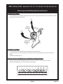
Main Setup Guide
Models 159, 160, 172, 173, 452, 453, 467, 468, 490, 491, 493
12955 Enterprise Way
Bridgeton, MO 63044-1200
(314) 298-3510
1590050
March, 1999
What is this booklet for?
This Main Setup Guide covers all the machines in the snack family. You will find out how
to install your machine in its final location, how to install accessories, and how to set up
and customize the snack trays.
If your machine is equipped with a coffee section, a can module, or a food module, you will
be instructed when to consult the booklets specifically provided for those items. Follow the
instructions given here, and you will be successful.
DON'T THROW THIS BOOKLET AWAY !! It's a valuable reference for your daily maintenance. Put it back in the plastic bag and store it inside the cabinet. That way, it is readily
available at a future time.
Main Setup Guide - Models 159, 160, 172, 173, 452, 453, 467, 468, 490, 491, 493
TABLE OF CONTENTS
Specifications ................................................................................................................................................... iii
Electrical Power Requirements ......................................................................................................................... 1
Unpack the Machine ......................................................................................................................................... 1
Controls and Indicators ..................................................................................................................................... 2
Fuse for Coin Mechanism DC Power Supply ................................................................................................... 3
How to Turn the Merchandiser ON and OFF .................................................................................................... 4
Initial Set-Up .................................................................................................................................................... 5
1. Move the Merchandiser through a Narrow Doorway ............................................................................ 5
2. Position the Merchandiser .................................................................................................................... 6
Snack Section Set-Up ..................................................................................................................................... 8
1. Place a Tray in the Loading Position .................................................................................................... 8
2. Set Up Trays to Vend Products ............................................................................................................ 9
Set Up a Tray to Vend Wide Products ................................................................................................. 9
Removing a Tray ................................................................................................................................ 10
Removing and Installing Column Dividers......................................................................................... 11
Operate a Tray Outside the Machine ................................................................................................. 12
Replacing a Motor with a Spiral Bearing............................................................................................ 13
Connecting and Disconnecting a Motor Harness ............................................................................... 13
Removing and Installing Spirals ........................................................................................................ 14
Removing a Spiral Coupler ................................................................................................................ 16
Removing and Installing a Spiral Motor ............................................................................................. 16
Installing a Gear ................................................................................................................................. 17
Installing a Spiral Coupler .................................................................................................................. 18
Moving a Tray Up or Down ................................................................................................................ 20
Installing a Tray in the Merchandiser ................................................................................................. 21
3. Load Trays with Product ..................................................................................................................... 22
4. Return the Trays to the Vending Position ........................................................................................... 26
5. Install Price Labels and Selection ID Labels ...................................................................................... 27
Set Up The Gum and Mint Unit ................................................................................................................... 29
1. Install Price Labels ............................................................................................................................. 29
2. Put the Gum and Mint Dispenser in the Loading Positon .................................................................. 29
3. Load the Gum and Mint Dispenser With Product ............................................................................... 30
4. Return the Gum and Mint Dispenser to the Vending Position ............................................................ 31
5. Removing and Installing Column Reducers ...................................................................................... 31
Final Installation ........................................................................................................................................... 32
1. Level the Merchandiser ...................................................................................................................... 32
A. Connect a Refrigeration Module to an External Drain (optional) ....................................................... 33
2. Install the Base Plate .......................................................................................................................... 34
3. Install the Lock Cylinder ..................................................................................................................... 35
4. Install the Optional Cash Box Lock .................................................................................................... 35
5. Set Up the Coin Mechanism ............................................................................................................... 36
6. Load the Coin Mechanism .................................................................................................................. 36
1590050
PAGE i
Main Setup Guide - Models 159, 160, 172, 173, 452, 453, 467, 468, 490, 491, 493
Programming ................................................................................................................................................. 37
Overall Programming Flow Chart ............................................................................................................ 37
Service Programming Flow Chart ........................................................................................................... 38
Setup Programming Flow Chart .............................................................................................................. 39
Coffee Programming Flow Chart ............................................................................................................. 40
DATA ........................................................................................................................................................ 41
PAY OUT ................................................................................................................................................. 42
PRICE ...................................................................................................................................................... 42
FAULTS ................................................................................................................................................... 43
SERVICE ................................................................................................................................................. 44
SETUP ..................................................................................................................................................... 45
COFFEE .................................................................................................................................................. 47
TIME OF DAY FEATURES ...................................................................................................................... 48
PAGE ii
1590050
Main Setup Guide - Models 159, 160, 172, 173, 452, 453, 467, 468, 490, 491, 493
SPECIFICATIONS
DIMENSIONS AND WEIGHTS
MODEL
HEIGHT
WIDTH
DEPTH
SHIPPING WEIGHT
159
183 cm (72 in)
97 cm (38.1 in)
90 cm (35.4 in)
284 kg (626 lbs)
160
183 cm (72 in)
81.3 cm (32 in)
90 cm (35.4 in)
256 kg (564 lbs)
172
183 cm (72 in)
97 cm (38.1 in)
72.4 cm (28.5 in)
259 kg (572 lbs)
173
183 cm (72 in)
81.3 cm (32 in)
72.4 cm (28.5 in)
214 kg (472 lbs)
452
183 cm (72 in)
97 cm (38.1 in)
72.4 cm (28.5 in)
295 kg (650 lbs)
453
183 cm (72 in)
81.3 cm (32 in)
72.4 cm (28.5 in)
249 kg (550 lbs)
467
183 cm (72 in)
97 cm (38.1 in)
90 cm (35.4 in)
320 kg (705 lbs)
468
183 cm (72 in)
81.3 cm (32 in)
90 cm (35.4 in)
270 kg (595 lbs)
490
183 cm (72 in)
81.3 cm (32 in)
90 cm (35.4 in)
324 kg (714 lbs)
493
183 cm (72 in)
101.6 cm (40 in)
90 cm (35.4 in)
362 kg (798 lbs)
CIRCUIT RATING
230 VOLT, 50 HZ MACHINES
CIRCUIT RATING
115 VOLT, 60 HZ MACHINES
MODEL
CURRENT (AMPS)
MODEL
CURRENT (AMPS)
159/160
3
159/160
3
172/173
3
467/468
9
452/453
5
490
12
467/468
5
493
16
CIRCUIT RATING
220 VOLT, 50 HZ MACHINES
MODEL
CURRENT (A MPS)
490
5
REFRIGERATION SPECIFICATIONS
UNIT
REFRIGERANT
CHARGE
CHILLED SNACK
R-134a
248 g (8.75 oz)
CAN/COLD FOOD
R-134a
277 g (9.8 oz)
FROZEN FOOD
R-404a
215 g (7.59 oz)
Operating environment - All models: FOR INDOOR USE ONLY
Ambient Temperature
Maximum
Minimum
32°C (90°F)
5°C (41°F)
1590050
PAGE iii
TH
IS
PA
GE
IN
TE
NT
IO
NA
LL
Y
LE
FT
BL
AN
K
Main Setup Guide - Models 159, 160, 172, 173, 452, 453, 467, 468, 490, 491, 493
PAGE iv
1590050
Main Setup Guide - Models 159, 160, 172, 173, 452, 453, 467, 468, 490, 491, 493
Electrical Power Requirements
The merchandiser is supplied with a service cord for the country of use and is terminated in a grounding type
plug. The wall receptacle used for this merchandiser must be properly polarized, grounded, and of the correct
voltage. Operating the merchandiser from a source of low voltage will VOID YOUR WARRANTY. Each merchandiser should have its own electrical circuit and that circuit should be protected with a circuit breaker or
fuse conforming to local regulations.
Voltage Check - Place the leads of a voltmeter across the LINE (LIVE) and NEUTRAL
terminals of the wall receptacle. The voltmeter should indicate 110-130 volts ac for 120
volt, 60 Hz locations, or 220- 240 volts ac for 230 volt, 50 Hz locations.
Polarity Check - Place the leads of a voltmeter across the LINE (LIVE) and GROUND
terminals of the wall receptacle. The voltmeter should indicate 110-130 volts ac for 120
volt, 60 Hz locations, or 220- 240 volts ac for 230 volt, 50 Hz locations.
Noise Potential Check - Place the test leads of a voltmeter across the NEUTRAL and
GROUND terminals of the wall receptacle. The meter should indicate 0 volts ac. A measurement greater than 1.5 - 2.0 volts ac could result in problems for the merchandiser's
electronic circuitry caused by electrical noise.
Any deviation from these requirements could result in unreliable performance from your merchandiser.
Unpack the Machine
Remove all packing materials from the interior of the machine. Keep all documents; warranty cards, etc.
Set aside the base plate kit (if present).
1590050
PAGE 1
Main Setup Guide - Models 159, 160, 172, 173, 452, 453, 467, 468, 490, 491, 493
Controls and Indicators
Interlock Switch. When the cabinet door is
open, this switch turns off the optional fan (if
so equipped) and turns on the service light
(not present on all models).
Low Voltage Switch. Informs the controller
software of the main door open or closed
status.
Message Display. This is how the merchandiser communicates with the outside world.
Customers can see messages about how
much money they have put into the merchandiser. The message display also tells customers when a selection is sold out and
when vending is free. The message display
shows you what you are doing when you program the merchandiser, and can show you
what is wrong if there is a failure.
INTERLOCK
SWITCH
MESSAGE
DISPLAY
CABINET
INSTRUCTION
PLATE
Selection Switch Panel. The customer
uses these switches to make selections.
Also, maintenance people may use this
switch panel during programming and other
support modes.
Coin Return Button. Pressing this button
returns any coins that have been paid into
the merchandiser prior to a vend.
Bill Acceptor (Optional). Accepts bills in
various denominations, depending upon the
type of bill validator, and how the machine is
configured.
PAGE 2
LOW VOLTAGE
SWITCH
SELECTION
SWITCH
MONETARY
PANEL
COIN
RETURN
BUTTON
1590050
BILL
ACCEPTOR
(OPTIONAL)
COIN
INSERT
Main Setup Guide - Models 159, 160, 172, 173, 452, 453, 467, 468, 490, 491, 493
MAIN CONTROLLER PCB DISPLAY
MAIN CONTROLLER
PCB ASSEMBLY
LED1 LED2
POWER ON
(L.E.D. 1)
FLASHING
HEARTBEAT
(L.E.D. 2)
Main Controller PCB Display. This display consists of two light emitting diodes (LED) mounted on the
controller PCB.
POWER ON
(L.E.D. 1)
When lit, this red LED indicates electrical power is applied to
the controller PCB.
HEARTBEAT When flashing, this red LED indicates that the controller PCB is
(L.E.D. 2)
active, and the software is operating.
NORMAL CONDITIONS:
When the merchandiser is operating normally, you should see a steady red
POWER ON indicator and a flashing red HEARTBEAT indicator. Contact a
service representative if any other condition exists.
TOP
AGC 1
FUSE
1 AMP
˜
DC POWER
Fuse for Coin Mechanism DC Power Supply
SUPPLY PCB
(U.S./Canada Only). The circuit board mounted
FOR COIN MECH
on the rear of the power panel is a dc power supply for the coin mechanism. A fuse protects the
board circuitry in the event of a coin mechanism solenoid failure.
If the coin mechanism is not working, check this fuse. If the fuse is
blown, a bad coin mechanism solenoid could be at fault.
C
1590050
S
PAGE 3
Main Setup Guide - Models 159, 160, 172, 173, 452, 453, 467, 468, 490, 491, 493
How to Turn the Merchandiser ON and OFF
I
LABEL
O
MAIN
POWER
SWITCH
ELECTRONICS
BREAKER
POWER CONTROL PANEL
STANDARD
POWER CONTROL PANEL
GERMANY
POWER PANEL
•
•
Power to the merchandiser is controlled by the main power switch, located on the power panel.
The power panel is on the right side of the merchandiser, behind the monetary door.
WARNING
- ELECTRICAL SHOCK HAZARD - Lethal voltages are present.
Unplug the merchandiser whenever you do one of the following tasks.
Failure to do so may result in personal injury:
• Change a fuse
• Change the fluorescent lamp
• Change the lamp starter
• Connect or disconnect a harness (except a motor harness when a
tray has been removed)
PAGE 4
1590050
Main Setup Guide - Models 159, 160, 172, 173, 452, 453, 467, 468, 490, 491, 493
Initial Set-Up
1. Move the Merchandiser Through a Narrow Doorway
Some models have removable panels at the top
and bottom of the cabinet. If necessary, the merchandiser can be moved through an opening as
narrow as 30 inches by removing these panels.
REMOVABLE PANEL
FOR GETTING THROUGH
A NARROW DOORWAY
REMOVE THE TOP PANEL:
1.
2.
Remove the two screws that secure
each end of the panel to the cabinet.
Pull the panel forward to remove it
from the merchandiser.
VIEW LOOKING INTO THE TOP OF THE CABINET
REMOVE THE BOTTOM PANEL:
1.
2.
REMOVABLE PANEL
FOR GETTING THROUGH
A NARROW DOORWAY
Remove the screws that secure the
panel to the cabinet.
Pull the panel forward to remove it
from the cabinet.
˜
VIEW LOOKING INTO THE BOTTOM OF THE CABINET
1590050
PAGE 5
Main Setup Guide - Models 159, 160, 172, 173, 452, 453, 467, 468, 490, 491, 493
1. Move the Merchandiser Through a Narrow Doorway (continued)
TAKE THE MERCHANDISER THROUGH THE OPENING:
1.
2.
Open the cabinet door and place it square with
the left side of the cabinet.
Carefully walk the merchandiser through the
opening.
REASSEMBLE THE MERCHANDISER:
1.
Replace the upper and
lower panels.
2. Position the Merchandiser
Move the merchandiser to its approximate position. (There are some procedures you need to do before
it is in its permanent location.) Plug in your merchandiser and turn the power switch to ON.
• You can position this merchandiser anywhere in a bank of machines. It can even be placed on an
end flush against a side wall.
• Place the merchandiser at least six inches away from the back wall. This will provide adequate air
circulation for the refrigeration unit.
• The merchandiser will operate more efficiently when placed in a shaded location.
• There should be enough room in front of the merchandiser for the door to move freely.
WARNING
This machine is only rated for installation in an indoor location.
PAGE 6
1590050
Main Setup Guide - Models 159, 160, 172, 173, 452, 453, 467, 468, 490, 491, 493
TIME OUT !!!
Now that you have placed your machine near its permanent location, you need to set up some of the
special options you may have.
IF YOUR MACHINE HAS A COFFEE SECTION
(493) . . .
Grab the booklet entitled "HOT DRINK MODULE SETUP, OPERATION AND SERVICE MANUAL" and
follow the setup procedures contained in it. After you have done that, come right back here and proceed with the next step.
N
E
X
T
NOW, IF YOUR MACHINE IS EQUIPPED WITH A CAN
OR COLD FOOD MODULE . . .
Grab the booklet entitled "CAN AND COLD FOOD MODULE SETUP AND OPERATOR'S GUIDE" and
follow the setup procedures contained in it. After you have done that, come right back here and proceed with the next step.
N
E
X
T
Go on to the next page and continue with the snack set up.
1590050
PAGE 7
Main Setup Guide - Models 159, 160, 172, 173, 452, 453, 467, 468, 490, 491, 493
Snack Section Set-Up
1. Place A Tray In The Loading Position
1.
2.
3.
4.
5.
Place both hands on the tray as shown.
If your machine has tray latches, lightly push back on the tray with your palms. This will release the
tray latches on the sides of the tray. Otherwise, skip to step 5.
Push down on the tray latches with your thumbs.
Pull the tray toward you until you hear and feel the rear tray rollers drop into a cut-out in the top of
the guide rail. Skip to step 6
Lightly lift the front of the tray and pull the tray toward you until you hear and feel the rear tray rollers drop into the cut-out in the top of the guide rail.
TRAY
LATCH
PULL
6.
TRAY
LATCH
Continue pulling the tray forward for another inch. You will then be able to tilt the tray downward into
the loading position as shown.
NOTE
When the cabinet door is not fully open, the bottom tray will rest on the
delivery pan assembly. Handle the tray with care to avoid scratching the
delivery pan assembly.
PAGE 8
1590050
Main Setup Guide - Models 159, 160, 172, 173, 452, 453, 467, 468, 490, 491, 493
2. Set Up Trays to Vend Products
These instructions will guide you through setting up your trays for vending. You will be asked to determine if your tray can physically hold the products you intend to vend. If not, you will be directed to other
procedures which will help you get them set up. Follow these nine steps for each tray in your machine:
1.
2.
3.
4.
5.
6.
7.
8.
9.
Make sure the tray is in the loading position.
Is the column wide enough for the intended product? If so, proceed to the next step. Otherwise,
set up your tray to vend wider products (see below, this page). When you're done, return to step 3
in this procedure.
Will the products fit between the spiral turns? If so, proceed to the next step. Otherwise, change
the spiral.
Will the product pass under the tray immediately above? If so, proceed to the next step. Otherwise, reposition the tray and guides.
Will the product touch products on either side? If not, proceed to the next step. Otherwise, install a
product spacer.
Load products in the tray.
Return the tray to the vending position.
Install the price rolls.
Install the selection ID numbers.
Set Up A Tray To Vend Wide Products
The following steps will help you configure your tray to vend wide products. When you have completed
the procedures called out in each step, return to the next step in the procedure. When you are done
with the entire wide product steps, return to the set-up procedures above.
1.
2.
3.
4.
5.
6.
Remove the tray from the merchandiser and place on a flat surface. See REMOVING A TRAY.
You may couple two spirals together with one condition: Please remember that the left spiral of the
pair must have an even ID number (0, 2, 4, etc.).
Remove the column dividers between the pair.
Replace the right motor with a spiral bearing and gear and install a gear on the left motor. See REPLACING A MOTOR WITH A SPIRAL BEARING.
Return the tray to the merchandiser.
Return to step 3 in the Set Up Trays to Vend Products procedure, above.
1590050
PAGE 9
Main Setup Guide - Models 159, 160, 172, 173, 452, 453, 467, 468, 490, 491, 493
Removing a Tray
•
1.
2.
Study this procedure before you install a tray for the first time; while you
are holding the tray you will not be
able to see this area. Proceed as
follows:
TRAY
LATCH
If your machine has tray latches,
push back on the tray slightly with
your palms. This releases the tray
latches. Otherwise, skip to step 4.
Push down on the tray latches with
your thumbs.
PULL
TRAY
LATCH
TRAY
LATCH
3.
4.
Pull the tray forward until you hear and feel the rear tray
rollers drop into a cut-out in the top of the guide rail.
Skip to step 5.
Lightly lift the front of the tray and pull the tray toward
you until you hear and feel the rear tray rollers drop into
a cut-out in the top of the guide rail.
TRAY
GUIDE
RAIL
5.
PC BOARD
ATTACHED TO
TRAY GUIDE
Unplug the tray wiring harness from the PC board
mounted on the tray guide rail
JUST ABOVE the tray you
are removing.
TRAY GUIDE RAIL
PAGE 10
1590050
Main Setup Guide - Models 159, 160, 172, 173, 452, 453, 467, 468, 490, 491, 493
Removing a Tray (continued)
5.
REAR OF TRAY
Lift up on the tray and slide it toward the back. No
more than an inch should be needed.
CUT-OUT
REAR OF
TRAY
TRAY
ROLLER
TAB
(ON TRAY)
6.
TRAY GUIDE
RAIL
TRAY
GUIDE
RAIL
The tab near the back of the tray should align with the cutout in the top of the tray guide rail as shown.
Lift the tray clear of the tray guide rail and out of the merchandiser.
7.
CAUTION
When the cabinet door is not fully open, use extra care in removing the
bottom tray. Failure to do so may result in damage to the tray or to the
delivery pan assembly.
Removing And Installing Column Dividers
1.
Push the column divider toward the back of the tray -
.
2
1
COLUMN
DIVIDER
2.
3.
Lift the column divider clear of the tray .
Install the column divider in the reverse order of removal.
1590050
PAGE 11
Main Setup Guide - Models 159, 160, 172, 173, 452, 453, 467, 468, 490, 491, 493
Operate a Tray Outside the Machine
Tray harness extension (P/N 1709017) is available from your GPL Parts department.
The extension will enable you to remove the tray from the machine and still operate the
motors and spirals. Connect it as shown:
PAGE 12
1590050
Main Setup Guide - Models 159, 160, 172, 173, 452, 453, 467, 468, 490, 491, 493
Replacing a Motor With a Spiral Bearing
REMOVING A MOTOR:
1.
2.
3.
4.
Disconnect the harness from the motor. See CONNECTING AND DISCONNECTING A MOTOR
HARNESS, below.
Remove the spiral. See REMOVING AND INSTALLING SPIRALS.
Remove the spiral coupler. See REMOVING A SPIRAL COUPLER.
Remove the motor. See REMOVING AND INSTALLING A SPIRAL MOTOR.
INSTALLING A SPIRAL BEARING:
1.
2.
Put the gear into position if required in this set-up as shown. See INSTALLING A GEAR.
Install the spiral coupler. See INSTALLING A SPIRAL COUPLER.
SPIRAL
BEARING
BACKWALL
OF TRAY
GEAR
˜
SPIRAL
COUPLER
Connecting and Disconnecting a Motor Harness
MOTOR
HARNESS
CAUTION
To avoid breaking the motor circuit board, hold the
header on the circuit board whenever connecting
or disconnecting a motor harness.
DISCONNECTING A MOTOR HARNESS:
1.
2.
Pull the harness connector away from the circuit board as
shown.
Tuck the unused part of the harness out of the way in the
trough at the back of the tray.
CONNECTING A MOTOR HARNESS:
1.
2.
Locate the harness connector for the appropriate tray position.
Push the harness connector over the header pins on the
motor circuit board as shown.
1590050
MOTOR
PAGE 13
Main Setup Guide - Models 159, 160, 172, 173, 452, 453, 467, 468, 490, 491, 493
Removing and Installing Spirals
•
All spirals are the same diameter:
•
There are two types of spirals:
COUNTER-CLOCKWISE (left hand)
•
CLOCKWISE (right hand)
Spirals are available as follows:
SPIRALS FOR MODELS 172, 173, 452, AND 453
SPIRALS FOR MODELS 159, 160, 467, 468, 490,
AND 493
ITEM
CAPACITY
OF SPIRAL
6 (Optional)
PART NUMBER
COUNTERCLOCKWISE
CLOCKWISE
(RH)
(LH)
1477102
1477104
ITEM
CAPACITY
OF SPIRAL
CLIP
COLOR
PART NUMBER
COUNTERCLOCKWISE
CLOCKWISE
(RH)
(LH)
1707017
1707019
Purple
8
Gray
10
1707005
1477027
Blue
12
1477033
Yellow
14
1477036
1477039
Red
18
17 (Standard)
1477101
1477099
Brown
20 (Standard)
1477042
1477045
White
25 (Optional)
1477048
1477051
Green
30 (Optional)
1477054
1477057
Black
38 (Optional)
1477059
1477062
Orange
9 (Standard)
1477152
1477149
11 (Standard)
1477024
13 (Standard)
1477030
15 (Standard)
PAGE 14
1590050
CLIP
COLOR
Grey
1707007
Blue
1707009
1707011
Yellow
1707013
1707015
Red
1707021
1707023
White
Main Setup Guide - Models 159, 160, 172, 173, 452, 453, 467, 468, 490, 491, 493
Removing and Installing Spirals (continued)
TO REMOVE A SPIRAL:
1.
2.
Pull forward on the retaining clip and remove the end of the spiral from the spiral coupler as shown.
Remove the spiral from the tray.
LIFT
SPIRAL
COUPLER
PULL
SPIRAL
RETAINING
CLIP
TO INSTALL A SPIRAL:
1.
2.
3.
Pull the bottom of the retaining clip toward the front of the spiral.
Lower the spiral into the tray column and insert the end of the spiral into the spiral coupler as
shown.
Release the retaining clip.
SHOULD I USE A CLOCKWISE OR A COUNTERCLOCKWISE SPIRAL?
1.
2.
The type of spiral used is determined by the column position it will occupy in the tray.
Refer to the figure below to find the correct spiral type.
A0
A1
A2
A3
A4
A5
1590050
A6
A7
A8
A9
PAGE 15
Main Setup Guide - Models 159, 160, 172, 173, 452, 453, 467, 468, 490, 491, 493
Removing a Spiral Coupler
1.
2.
Pinch together the prongs on the end of the spiral coupler as shown.
Pull the coupler forward (in the direction of the arrow as shown).
SPIRAL
COUPLER
PRONGS
PULL
Removing and Installing a Spiral Motor
REMOVING A SPIRAL MOTOR:
steps may already be completed.
1.
2.
3.
4.
5.
6.
NOTE, some
Remove the tray. See REMOVING A TRAY.
Disconnect the motor harness. See CONNECTING AND DISCONNECTING A MOTOR HARNESS.
Remove the spiral. See REMOVING AND INSTALLING SPIRALS.
Remove the spiral coupler. See REMOVING A
SPIRAL COUPLER.
Remove any fasteners and lift the motor clear of
the tray.
Return the tray to the merchandiser. See INSTALLING A TRAY IN THE MERCHANDISER.
3.
4.
5.
6.
213;G1<<
?6DB1I
Ñ
751B
C@9B1<
INSTALLING A SPIRAL MOTOR:
1.
2.
SPIRAL
MOTOR
(MODELS 452 AND 453
ARE ROTATED 90°)
3?E@<5B
Remove the tray. See REMOVING A TRAY.
Place the motor in the correct position at the rear of the tray
as shown. Secure with fasteners, if applicable.
Place a gear in position if required by this set-up. See
INSTALLING A GEAR.
Install a spiral coupler in the proper orientation. See INSTALLING A SPIRAL
COUPLER.
Connect the motor harness. See CONNECTING AND DISCONNECTING A MOTOR HARNESS.
Return the tray to the merchandiser. See INSTALLING A TRAY IN THE MERCHANDISER.
PAGE 16
1590050
Main Setup Guide - Models 159, 160, 172, 173, 452, 453, 467, 468, 490, 491, 493
Installing a Gear
WHEN ARE GEARS USED?
•
•
Gears are used to mechanically couple the spirals together.
This happens whenever you have two spirals and only one motor for vending a selection.
WHERE ARE THE GEARS PLACED?
•
The gear is placed between the back of the tray and the spiral coupler.
HOW IS THE GEAR ORIENTED?
•
There are two possible orientations for the gear:
BACK WALL
OF TRAY
GEAR
ORIENTATION 1
•
ORIENTATION 2
There are two rules to follow when orienting gears:
RULE 1 - The gears for selections next to each other cannot use the same orientation.
RULE 2 - All gears for a single selection must use the same orientation.
1590050
PAGE 17
Main Setup Guide - Models 159, 160, 172, 173, 452, 453, 467, 468, 490, 491, 493
Installing a Spiral Coupler
1.
Place the gear in position if one is required for this set-up. See INSTALLING A GEAR.
WHEN USED WITH A MOTOR:
2.
Hold the motor in place and push the spiral coupler through the motor gear box until it clicks into
position. Be sure the spiral couplers are oriented as
shown below.
SPIRAL
COUPLER
NOTE
The motor output shaft opening
contains eight facets to allow the
spiral coupler to be installed
in any one of eight
positions.
FRONT VIEW OF
MOTOR OUTPUT SHAFT
MOTOR
SPIRAL COUPLER ORIENTATION
ONE POSITION
COUNTERCLOCKWISE
FROM VERTICAL
ONE POSITION
CLOCKWISE
FROM VERTICAL
LEFT SPIRAL
COUPLER
RIGHT SPIRAL
COUPLER
AS VIEWED FROM FRONT OF TRAY
PAGE 18
1590050
Main Setup Guide - Models 159, 160, 172, 173, 452, 453, 467, 468, 490, 491, 493
Installing a Spiral Coupler (continued)
WHEN USED WITH A COUPLER BEARING:
2.
Hold the coupler bearing in place and push the spiral coupler through the bearing until the coupler
clicks into position. Be sure the coupler is in the proper orientation as shown.
SPIRAL
COUPLER
SPIRAL
BEARING
1590050
PAGE 19
Main Setup Guide - Models 159, 160, 172, 173, 452, 453, 467, 468, 490, 491, 493
Moving a Tray Up or Down
This merchandiser can be adjusted to vend taller products. Some guidelines must be followed:
•
Keep in mind that when you increase the product height available to a tray by lowering it, you will be
decreasing the product height available to the tray below.
•
If a tray is in the lowest position, the tray below it should not be in the highest position.
•
If a tray is in the highest position, the tray above it should not be in the lowest position.
•
You will need to experiment with various tray positions to get the best results for your products.
CAUTION
Trays should not be positioned over an open air discharge vent.
NOTE
Tray movement is limited because the tray harness will limit the amount of
travel available to the tray guide rails.
Proceed as follows:
1.
2.
Remove the tray from the merchandiser. See REMOVING A TRAY.
Remove the screw that secures the right tray guide rail to the front guide mounting channel as
shown.
3. Tap up on the guide rail and unseat the guide rail tabs from the channel slots.
4. Pull the guide rail away from the front and rear guide mounting channels.
5. Move the guide rail to the desired position.
REAR GUIDE
6. Insert the guide rail tabs into
MOUNTING CHANNEL
the mounting CVchannel slots
as shown.
7. Tap down on the guide rail to
seat the tabs in the channel
slots.
8. Replace the screw that secures
PC BOARD
FRONT GUIDE
the guide rail to the front guide
MOUNTING CHANNEL
mounting channel.
9. Repeat steps 2 through 8 for the
CHANNEL
SLOT
left guide rail.
10. Return the tray to the merchandiser. See
INSTALLING A TRAY IN THE MERCHANDISER.
11. Load products into the trays, and perform test vends.
TRAY
GUIDE
Make sure the trays don't interfere with the products you
RAIL
are vending, and that all products vend properly.
SCREW
PAGE 20
1590050
Main Setup Guide - Models 159, 160, 172, 173, 452, 453, 467, 468, 490, 491, 493
Installing a Tray in the Merchandiser
•
Study this procedure before you install a tray for the first time; while you are holding the tray you will
not be able to see this area. Proceed as follows:
1.
Insert the tray so that the tray rollers pass
over the tray guide rollers.
5.
REAR OF
TRAY
Hold the tray up while pushing it toward the
rear. Stop when the tab on the tray aligns
with the opening in the tray guide.
CUT-OUT
REAR OF
TRAY
TRAY
GUIDE
TRAY
ROLLER
TAB
(ON TRAY)
FRONT OF
RAIL
2.
TRAY GUIDE
RAIL
Bring the tray roller to rest on the tray guide.
6.
REAR OF TRAY
7.
Lower the tray until it rests on the tray guide
roller. Push the tray in all the way.
The tray latch (if so equipped) will fall into the
locking position.
TRAY
LATCH
TRAY
ROLLER
TRAY
GUIDE
RAIL
TRAY
GUIDE
RAIL
3.
Tilt the tray upward.
4.
Connect the tray wiring harness to the PC
board mounted to the guide rail JUST ABOVE
the tray you are installing.
1590050
PAGE 21
Main Setup Guide - Models 159, 160, 172, 173, 452, 453, 467, 468, 490, 491, 493
3. Load Trays With Product
SPIRAL CAPACITY COLOR CODES
(MODELS 159, 160, 467, 468, 490, AND 493)
SPIRAL SPIRAL COUPLER
SPIRAL SPIRAL COUPLER
CAPACITY
CAPACITY
COLOR
COLOR
6
9
11
13
15
Purple
Gray
Blue
Yellow
Red
17
20
25
30
38
Brown
White
Green
Black
Orange
The color of the spiral coupler
(the little plastic tab attached
to the rear of the spiral will tell
you how many products will fit
in the spiral. See table at left.
NOTE
Another way to determine spiral
capacity is to count the spaces in
the spiral !
SPIRAL CAPACITY COLOR CODES
(MODELS 172, 173, 452, AND 453)
SPIRAL
SPIRAL COUPLER COLOR
CAPACITY
8
10
12
14
18
Gray
Blue
Yellow
Red
White
LOADING A TRAY WITH PRODUCTS IN GENERAL:
•
•
•
•
•
See PRODUCT PUSHER USAGE for spirals with capacity of 11, 13, or 15.
See SPIRAL WALL RETAINER USAGE for spirals with capacity of 20, 25, 30, or 38.
Begin loading products at the front of the tray and work toward the back. Position the product so
the package rests on the tray. DO NOT force a product into a spiral.
If the fit is too tight or too loose, change the spiral size. See REMOVING AND INSTALLING A
SPIRAL.
Be sure there are no empty positions between products in each spiral.
SPECIAL CONSIDERATIONS:
Bagged Products -
Position package upright, then push the tops slightly toward the rear of the tray.
Also, see PRODUCT PUSHER USAGE.
Thin Packages
-
Position the package upright. Also, see SPIRAL WALL RETAINER USAGE.
KitKat
-
The two rightmost columns of
the candy tray are
designed to accept the KitKat
candy bar.
SNACK
PRODUCT
CANDY
PRODUCT
CORRECT LOADING
OF SNACKS
PAGE 22
1590050
CORRECT LOADING
OF CANDY
Main Setup Guide - Models 159, 160, 172, 173, 452, 453, 467, 468, 490, 491, 493
3. Load Trays With Product (continued)
SPIRAL WALL RETAINER USAGE:
SPIRAL
WALL
RETAINER
A spiral wall retainer serves to compress the spiral and make it act like a
spring to more forcefully eject a product. Do some test vends and use a
spiral wall retainer when a product does not readily leave the spiral.
•
•
•
•
Use a spiral wall retainer in the following cases:
- The spiral has a capacity of 20, 25, 30, or 38.
- The product is thin.
- The product is on a candy tray.
The spiral wall retainer can also be used with other spirals and types of
products.
The spiral wall retainer is installed near the front of the column divider.
There are two ways to install the spiral wall retainer.
DIVIDER
COLUMN
DIVIDER
BETWEEN
THESE
POSITIONS
RETAINER
ORIENTATION
A
B
0 and 1
1 and 2
2 and 3
3 and 4
4 and 5
5 and 6
6 and 7
7 and 8
8 and 9
ORIENTATION A
•
•
ORIENTATION B
To install a spiral wall retainer, insert the retainer in the square slot near the front of the column divider.
The spiral wall retainer must be removed in two cases:
- A Kit-Kat bar loaded into either of the two right hand positions of a tray will not clear the retainer
on the column divider between the two positions.
- A product pusher will catch on a retainer in ORIENTATION A.
PRODUCT PUSHER USAGE (OPTIONAL):
The optional product pusher will give the top of a product an extra tilt to help it fall into the delivery pan.
PRODUCT
PUSHER
Use a product pusher in the following cases:
•
•
The spiral has a capacity of 15, 13, or 11.
The package is non-rigid like bagged peanuts
The product pusher can also be used with other spiral and types of products.
Product pushers are available from the parts department. To use a product pusher,
snap it on the spiral as shown. You can adjust the product pusher by moving it around on the spiral to
achieve the best vending results.
1590050
PAGE 23
Main Setup Guide - Models 159, 160, 172, 173, 452, 453, 467, 468, 490, 491, 493
3. Loading a Tray With Product (continued)
PRODUCT
SPACER
MOUNTING
PINS
MOUNTING
PINS
INSTALLING A PRODUCT SPACER:
The product spacer will keep a tall,
narrow product upright.
COLUMN
DIVIDER
Shown at right are product spacers
and column dividers on both deep and shallow trays. Insert the product spacer onto
the column divider as shown.
ADJUSTING A PRODUCT SPACER:
With product loaded in the tray, rotate the product spacer up or down
to keep the product upright as
shown.
REMOVING A PRODUCT SPACER:
Pull the product up off the column divider.
PAGE 24
1590050
Main Setup Guide - Models 159, 160, 172, 173, 452, 453, 467, 468, 490, 491, 493
3. Loading a Tray With Product (continued)
PREPARING THE MERCHANDISER FOR
VENDING "LUNCH BUCKET":
Because of the weight and shape of the package, it is recommended that this product be
vended only from the bottom tray.
ONE POSITION
COUNTERCLOCKWISE
FROM VERTICAL
ONE POSITION
CLOCKWISE
FROM VERTICAL
To vend this product, two adjacent positions
must be coupled together.
See INSTALLING A GEAR for mechanical coupling directions, or see the Programming Guide for electrical coupling
directions.
The left spiral coupler should be installed one
position counterclockwise from the vertical
position.
LEFT SPIRAL
COUPLER
RIGHT SPIRAL
COUPLER
The right spiral coupler should be installed
one position clockwise from the vertical position.
AS VIEWED FROM FRONT OF TRAY
Replace the current spirals with six-count spirals. These are available from the parts department. See REMOVING AND INSTALLING SPIRALS.
A pad can be installed in the bottom of the delivery pan to quiet and cushion product delivery. This part
is available from the parts department.
Load "Lunch Bucket" products as shown.
FOOD SELECTIONS
LOADED IN SPIRALS
Proper Loading of "Lunch Bucket"
1590050
PAGE 25
Main Setup Guide - Models 159, 160, 172, 173, 452, 453, 467, 468, 490, 491, 493
4. Return the Trays to the Vending Position
1.
Lift the tray until it is parallel to the floor as shown.
TRAY
LATCH
PULL
2.
TRAY
LATCH
Push the tray toward the back of the cabinet. If so equipped, the tray latches on the sides of the
tray will lock into position.
TRAY
LATCH
TRAY
GUIDE
RAIL
PAGE 26
1590050
Main Setup Guide - Models 159, 160, 172, 173, 452, 453, 467, 468, 490, 491, 493
5. Install Price Labels and Selection ID Labels
Price Labels
DOLLAR ROLL
Price labels are printed on coiled-up rolls. You will find
these in the plastic bag that contained this manual.
There are two types of price rolls: Dollar rolls (1 to 12
in increments of 1) and Cens rolls (00 to 95 in increments of 05)
CENTS ROLL
Price Label Installation
There are three pairs of slots in the front of the tray. Insert the dollar roll in the left-most pair of slots if the
price is $1.00 or more. Insert the cents roll in the center pair of slots. The low-number end of the roll goes
in the top slot and the high-number end of the roll goes in the bottom slot.
PRESS TOP OF ROLL
PAST FLEXIBLE TAB
NEAR TOP EDGE
INSERT BOTTOM OF ROLL
THROUGH SLOT ALONG
BOTTOM EDGE
Price Label Adjustment
You can set selection prices within the following range:
Minimum Price
$ .00
Maximum Price$12.95
Increment
$ .05
Use your thumb to move each price roll up or down as needed to set the
desired price.
1590050
PAGE 27
BOTTOM TRAY
Main Setup Guide
- Models 159, 160, 172, 173, 452, 453, 467, 468, 490, 491, 493
5. Install Price Labels and Selection ID Numbers (continued)
WHICH ID LABEL GOES WITH WHICH SELECTION?
See the figures below for snack and candy tray positions.
MOTOR POSITION
TOP TRAY TRAY A
A0
A1
A2
A3
A4
A5
A6
A7
A8
A9
TRAY B
B0
B1
B2
B3
B4
B5
B6
B7
B8
B9
TRAY C
C0
C1
C2
C3
C4
C5
C6
C7
C8
C9
TRAY D
D0
D1
D2
D3
D4
D5
D6
D7
D8
D9
TRAY E
E0
E1
E2
E3
E4
E5
E6
E7
E8
E9
FOOD SELECTION/CAN SELECTION/BOTTOM TRAY TRAY F
F0
F1
F2
F3
F4
F5
F6
F7
F8
F9
EXAMPLE OF A BASIC SNACK
TRAY ID LABEL TO USE
A0
A2
A4
A6
EXAMPLE OF A BASIC CANDY
TRAY ID LABEL TO USE
A0
PAGE 28
A1
1590050
A2
A3
A4
A5
A6
A7
Main Setup Guide - Models 159, 160, 172, 173, 452, 453, 467, 468, 490, 491, 493
Set Up The Gum and Mint Unit
1. Install Price Labels
The column ID labels have already been attached to the
delivery door, and a set of self-adhesive price labels are
in the plastic bag that contained this manual.
1.
Stick the desired price label next to the column ID
number as shown.
COLUMN
ID LABEL
2. Put the Gum and Mint Dispenser in the Loading Positon
The gum and mint assembly is hinged to the delivery
pan assembly and is held in the vending position by two
magnets. The gum and mint assembly is held in the
loading position by a hook and a loop. One end of the
hook is attached to the right side of the door. The loop
is mounted on the right side of the gum and mint assembly.
1.
Use the loop as a handle and raise the gum and
mint magazine with your left hand. With your right
hand, move the free end of the hook so it catches
the loop. This will hold the magazine while you are
loading it with product, as shown.
HOOK
LOOP
1590050
PAGE 29
Main Setup Guide - Models 159, 160, 172, 173, 452, 453, 467, 468, 490, 491, 493
3. Load the Gum and Mint Dispenser With Product
1.
The gum and mint assembly lid is held closed
by two magnets. Open the lid toward the inside of the merchandiser door.
PRODUCT
PUSHER
WARNING
Keep your hand on the product
pusher until it is locked in place.
Failure to do so may result in
personal injury or in damage to
the dispenser.
2.
FRONT
GLIDE
Move the product pusher into the loading position:
a. Pull back on the pusher.
b. Pull down on the pusher and lock the
front glide into position.
LOADING POSITION
PRODUCT
RETAINING LIP
˜
3.
Load the product:
a. Push the product forward.
b. Be sure the last item is completely under
the product retaining lip.
WARNING
Keep your hand on the product
pusher until it comes to rest
behind the last item in the
column. Failure to do so may
result in personal injury or in
damage to the dispenser.
4.
Move the product pusher into the dispensing
position:
a. Pull the product pusher down to unlock
the front glide.
b. Slide the product pusher toward the product.
DISPENSING POSITION
PAGE 30
1590050
Main Setup Guide - Models 159, 160, 172, 173, 452, 453, 467, 468, 490, 491, 493
4. Return the Gum and Mint Dispenser to the Vending Position
1.
2.
3.
4.
5.
Make sure all product pushers are in the vending position.
Close the gum and mint assembly lid.
Hold the loop on the right side of the magazine with
your left hand. Release the hook with your right hand
and lower the magazine.
Continue to hold the loop until the magazine has
been fully lowered.
Pivot the gum and mint assembly back to the vending position.
HOOK
LOOP
5. Removing and Installing Column Reducers
The two left-most vending columns (as seen from the loading side) can be adjusted for two different
widths.
When a column reducer is in place, the width of the column will be 31/16 inches.
When a column reducer is removed, the width of the column will be 37/8 inches.
TO REMOVE A COLUMN REDUCER:
1.
2.
Pull the reducer away from the cabinet door to disengage the locking tabs.
Lift up to remove the reducer from the gum and mint assembly.
TO INSTALL A COLUMN REDUCER:
1.
2.
LOCKING
TAB
Place the reducer on the gum and mint dispenser so the
locking tabs are in the slots.
Push the reducer toward the cabinet door to lock the reducer in place.
SLOT
COLUMN
REDUCER
1590050
PAGE 31
Main Setup Guide - Models 159, 160, 172, 173, 452, 453, 467, 468, 490, 491, 493
Final Installation
Some machines have a small square rear duct that must be installed before the machine is moved into
its final position. If your machine has this duct, locate it and follow the enclosed instructions.
Move the merchandiser to its final position:
• You can position this merchandiser anywhere in a bank of machines. It can even be placed on an
end flush against a side wall.
• Place the merchandiser at least six inches away from the back wall. This will provide adequate air
circulation for the refrigeration unit.
• There should be enough room in front of the merchandiser for the door to move freely.
WARNING
This machine is only rated for installation in an indoor location.
1. Level the Merchandiser
SPIRIT LEVEL
1.
2.
Place a spirit level on the top front edge of the cabinet
with the door fully closed. Adjust the front legs only until
the cabinet is reasonably level (figure 1).
Hold the door open about 4 inches. (This relieves any
stress the door may be placing on the cabinet.)
LEG
CRANE NATIONAL VENDORS
LEG
LEVELER
WARNING
Have an assistant hold the merchandiser while you
adjust the leg levelers.
3.
4.
Adjust the back legs so that the back leg leveler on the
hinge side is off the floor just enough so a piece of paper
can slide under it with only a bit of resistance (figure 2).
For proper weight distribution on all four legs, raise the
back leg on the hinge side by unscrewing the leveler 1½
turns.
FRO
NT
NOTE
You may need to use pliers or channel locks to loosen
the leg levelers.
When the merchandiser is part of a bank of machines, level it
in reference to the other machines. After leveling is complete,
check that the door operates easily.
LEFT REAR
LEG
1-1/2 TURNS
PAGE 32
1590050
Main Setup Guide - Models 159, 160, 172, 173, 452, 453, 467, 468, 490, 491, 493
Refrigeration Module
Complete the setup of chilled snack features (if present):
A. Connect a Refrigeration Module to an External Drain (optional)
METHOD 1:
REFRIGERATION
MODULE HOUSING
CONDENSATE
DRAIN TUBE
1.
TO
CONDENSATE
PAN
NEW DRAIN TUBE
(½ ID)
REFRIGERATION
MODULE HOUSING
Remove the condensate drain tube from the
refrigeration module.
2.
3.
METHOD 2:
TO EXTERNAL
DRAIN OR
OVERFLOW
BUCKET
Connect a new drain tube to the refrigeration
module housing.
Route the new tube to an external drain or to
an overflow bucket.
CONDENSATE
PAN
1.
2.
TO
EXTERNAL
DRAIN
Connect a drain tube to the condensate pan.
Route the drain tube to an external drain or to
an overflow bucket.
DRAIN TUBE
(½ ID)
O
1590050
PAGE 33
Main Setup Guide - Models 159, 160, 172, 173, 452, 453, 467, 468, 490, 491, 493
2. Install the Base Plate
Refer to the figure below while completing the following procedures:
WARNING
Do not move the cabinet while the hex head screws and/or carriage
bolts are loosened. The cabinet would become unstable and likely to
tip and cause injury.
1.
2.
3.
4.
5.
Remove the waste pail and the grounds pail from the merchandiser (refreshment center only).
Remove the floor liner from the merchandiser (refreshment center only).
Remove the two caps as shown.
Loosen the left leg assembly carriage bolts and nuts to allow mounting a base plate bracket.
Secure one of the base plate brackets to the leg assembly using the two carriage bolts. Tighten the
carriage bolts and nuts.
6. Loosen the right leg assembly hex screws to allow mounting the other base plate bracket.
7. Secure the other base plate bracket to the right leg assembly using the two hex head screws.
Tighten the hex head screws.
8. Insert the short arms of the slides into the hinged tabs of the base plate. Position the slide so the
notch near the short arm is on the bottom side.
9. Insert the long arms of the slides into the base plate brackets.
10. Insert and secure a cotter pin through the hole in the back of each of the slides.
11. Push the base plate toward the merchandiser cabinet. The front tabs of the base plate brackets
should seat in the notches in the long arms of the slides.
12. Replace the caps, liner, and pail(s) removed previously.
CAPS
COTTER PIN
SLIDE - LH
BASE PLATE BRACKET
SLIDE - RH
BASE PLATE
PAGE 34
1590050
Main Setup Guide - Models 159, 160, 172, 173, 452, 453, 467, 468, 490, 491, 493
3. Install the Lock Cylinder
Install an optional lock cylinder in the merchandiser as follows:
1.
2.
3.
4.
5.
6.
LOCK
SPRING
Position the lift handle lock lever as shown.
Depress the lock spring at the square hole of
the lock cylinder receptacle and pull the lock
springs out through the front.
Position the lock cylinder as shown. Depress
the spring loaded lock pin.
Push the cylinder into the cylinder receptacle
in the lever. The pin should snap into the
square hole.
If the cylinder pin does not seat in the square
hole, press against both ends of the lock cylinder. Rotate the cylinder until the pin snaps
into place.
Leaving the door open, test the lock mechanism with a key.
SQUARE
HOLE
KEY
LOCK
CYLINDER
LEVER
4. Install the Optional Cash Box Lock
1.
2.
3.
Remove the cash box from the merchandiser.
Assemble the lock as shown in the illustration to the right.
Return the cash box to the merchandiser.
LOCK BAR
SCREW
NUT
WASHER
LOCK
CYLINDER
1590050
PAGE 35
Main Setup Guide - Models 159, 160, 172, 173, 452, 453, 467, 468, 490, 491, 493
5. Set Up the Coin Mechanism
If the changer is not a MARS TRC 6000, proceed to LOADING THE COIN MECHANISM.
If the changer is a MARS TRC 6000, you must set the high quarter switch.
SETTING THE QUARTER SWITCH:
QUARTER SWITCH
POSITION
ACTION
LOW
The coin mechanism
will only store 6
quarters. The rest
are sent to the coin
box. Fewer quarters
are available for
change.
HIGH
The coin mechanism
will store 69 quarters.
More quarters are
available for change.
HIGH QUARTER
SWITCH
ON
1
2
3
4
6. Load the Coin Mechanism
1.
2.
3.
4.
Open the cabinet door.
Open the monetary door.
Insert coins one at a time until each of the coin tubes has been filled.
Inspect the tubes for shingled coins and correct if necessary.
PAGE 36
1590050
Main Setup Guide - Models 159, 160, 172, 173, 452, 453, 467, 468, 490, 491, 493
Programming
OVERALL PROGRAMMING FLOW CHART
Standby
Message
#
Total Sales
*
DATA
*
#
Total Vends
Total Free
Vend
"Sales"
*
#
Total Free
Vends
*
#
#
*
Test Vends
*
#
#
PAYOUT
(NDQ = 1 2 3)
#
PRICE
*
#
Price Individual
Selections.
#
FAULTS
*
#
Fault List.
#
SERVICE
*
#
See page 39 for a detailed description of
the SERVICE functions.
#
SETUP
*
#
See page 40 for a detailed description of
the SETUP FUNCTIONS.
#
COFFEE
*
#
See page 41 for a detailed description of
the COFFEE f unctions.
#
*
TIME OF DAY
Set Date.
#
*
Select Time
of Day Inhibit
Periods.
#
*
Set Start and
Stop Time.
*
#
#
The diagrams on the next few pages are maps of the programming functions in your merchandiser. These
functions will be described in greater detail in the text, but the diagrams will help you get around once you
are familiar with how programming works. Note that some features may not be available on your
merchandiser, depending upon how it is configured. The symbols
and # represent special keys that
move you around inside the programming modes, and from one mode to another. As you can see on the
diagram, these symbols show up in the pathways in and around the modes.
*
1590050
PAGE 37
Main Setup Guide - Models 159, 160, 172, 173, 452, 453, 467, 468, 490, 491, 493
SERVICE PROGRAMMING FLOW CHART
SERVICE
*
CUP DROP TEST
#
#
TEST VEND
*
*
SOFTWARE
VERSION
NUMBER
WHIPPER
TEST
#
*
*
COLD MODULE
TEMPERATURE
AIR COMPRESSOR
TEST (Fresh brew
only.)
#
FOOD DOOR TEST
(Food module equipped
units only.)
BREWER TEST
(Fresh brew only.)
#
#
*
BREWER AND BOWL
RINSE TEST
*
#
*
*
PAGE 38
#
*
*
COFFEE SECTION
SOFTWARE
VERSION NUMBER
#
1590050
#
Main Setup Guide - Models 159, 160, 172, 173, 452, 453, 467, 468, 490, 491, 493
SETUP PROGRAMMING FLOW CHART
SETUP
*
FREE VEND
ON/OFF
#
*
SELECT
COIN MECH.
#
*
SELECT
BILL
VALIDATOR
#
*
SET MACHINE
CONFIGURATION
#
*
*
SELECT
CARD
READER
TRAY
COUPLING
(FOOD MODULE
ONLY )
*
CHANGE
OPTIONS
#
EXACT
CHANGE
MESSAGE
OPTIONS
*
SELECT COLD
MODULE
TEMPERATURE
*
#
#
*
#
*
DECLINING
BALANCE
OPTIONS
#
*
SELECT
LANGUAGE
#
*
1590050
PAGE 39
Main Setup Guide - Models 159, 160, 172, 173, 452, 453, 467, 468, 490, 491, 493
COFFEE PROGRAMMING FLOW CHART
COFFEE
*
#
#
VIEW ACTIVE
SELECTIONS AND
SELECT FREEZE
DRY/FRESH BREW
(0, 4, 8, 9)
#
Press selection number
TURN
SELECTION
ON/OFF
(6)
*
*
#
SET UP
CAPPUCCINO
RATIO
#
SELECT
CUP SIZE
*
*
#
SET UP
RINSE TIME
(FB ONLY)
#
SET UP DRY
PRODUCT
THROW
*
#
*
SET UP
WATER
THROW
*
#
FB
Coff ee
SET UP STEEP
TIME
*
#
SET UP AIR
COMPRESSOR
TIME
*
#
SET UP
SUGAR
THROW TIME
*
#
SET UP
LIGHTENER
THROW TIME
*
SET UP
WHIPPER
OPTIONS
#
PAGE 40
*
1590050
WHAT
PRODUCT
IS BEING
SET UP?
FD
Coff ee
Choc.
Main Setup Guide - Models 159, 160, 172, 173, 452, 453, 467, 468, 490, 491, 493
THE KEYPAD
During vending, customers use the keypad to make
selections. When you pull the door switch to the
ON position, the keypad becomes your programming input device. For reference, we will show the
keypad on all the pages.
SPECIAL PROGRAMMING KEYS
Press this key to move from one function to another.
From within a function, press once to return to the beginning of the function; press and hold to
return to the standby message.
This key moves you around inside of a function.
This key allows you to switch between two or more choices.
This is the "action" key. It will start tests, fill the water tank, etc.
DATA
View several types of sales data:
NOTE
All data is not resettable.
1.
Pull out the door switch button to the ON position.
2.
Press
3.
If you have the DEX option, press
to transfer data into your DEX device.
4.
Press
. The display shows
NR$ .XX
. This is the dollar and cents amount of machine sales.
5.
Press
. The display shows
NR XX
6.
Press
. The display shows
not display if the total is zero.)
7.
Press
. The display shows
total is zero.)
8.
Press
. The display shows
total is zero.)
9.
Press
until the display shows DATA.
. This is the total count of all vends.
_0 .XX
. This is the dollar and cents amount of free vend "sales". (Does
_0 .XX
TST
to return to step 4, or
. This is the total count of free vends. (Does not display if the
. This is the total count of test vends. (Does not display if the
XX
to exit.
1590050
PAGE 41
Main Setup Guide - Models 159, 160, 172, 173, 452, 453, 467, 468, 490, 491, 493
PAY OUT (Does not apply to machines with EXEC coin mechanisms.)
Pay out coins:
1. Pull out the door switch button to the ON position.
2. Press # until the display shows
PAY
=
1.2.3
(MDB mech). This is telling you that pressing
dimes, and pressing
pays out nickels, pressing
pays out
pays out quarters.
OR
NDQ
=
1.2.3
(dumb mech). This is telling you that pressing
pays out from tube 1 (nickels),
3.
4.
pays out from tube 2 (dimes), and pressing
pays out from tube 3 (quarters).
pressing
Press the appropriate key once to pay out one coin.
Press and hold the appropriate key to pay out coins continuously.
5.
Press and hold
to return to the standby message.
PRICE
Set prices for all the selections in your merchandiser:
A0
The price display:
.25
Selection price
Selection number
and letter
1.
Pull out the door switch button to the ON position.
2.
Press
until the display shows PRICE.
3.
Press
, and the display shows
4.
Press
until the selection you want to price is displayed. NOTE: Only selections which are actualy
present in the machine can be accessed this way, except selection H, which can
always be priced.
A0 .XX
. "XX" is the price for the A0 selection.
OR
Press the letter and number of the selection you want to price, and it will be
displayed immediately. NOTE: All selections in the machine are accessible in this
way.
5.
6.
Enter a new price with the number keys.
Repeat steps 4 and 5 until you have priced all the selections.
OR
7.
Press
PAGE 42
to return to the PRICE display, or hold
1590050
to exit.
Main Setup Guide - Models 159, 160, 172, 173, 452, 453, 467, 468, 490, 491, 493
FAULTS
Display all the active faults on your merchandiser:
1.
Pull out the door switch button to the ON position.
2.
Press
until the display shows FAULTS.
3.
Press
to see the list of faults:
NO ERRORS
KEYPAD XY
ROM ERROR
RAM ERROR
There are no faults on the machine.
Key(s) “X” and “Y” are stuck.
The EPROM is bad.
RAM is not initialized or is not compatible with the currently loaded
software. If this message appears, initialize your RAM by performing
the following procedure:
NOTE: Initializing RAM will erase all your data and drink setings.
Be sure you have written this information down before continuing.
Press AND HOLD
. You will see
CLEARING
in the display. Continue
holding until two beeps are heard and the display shows
.
The water level in the tank is low.
The coffee section is not responding to the controller.
The food door has failed.
The health control has been set. "XX°F" is the maximum temperature
reached.
The temperature reference on the main PCB cannot be read.
The temperature sensor cannot be read.
The temperature sensor is out of range.
Out of cups.
The waste pail is full.
Problem with the bill validator.
The brewer is jammed or out of position.
Problem with the coin mechanism.
Time of day inhibit is active, or all selections are out of service.
Illegal price is detected.
Problem with the card reader.
FINISHED
LOW WATER
JCOMM ERR
FOOD XXX
HC.ERR XX
O
F
TEMP REF
TEMP SENSE
TEMP RANGE
CUPS ?
WASTE PAIL
DBV
ERR
BREWER
MECH ERR
NONE READY
CHK PRICE
CARD ERR
When the first fault item (if any) repeats, you have seen all the faults.
When active faults exist, pulling the door switch will automatically display
4.
Press
to see more faults or
.
FAULTS
to exit.
1590050
PAGE 43
Main Setup Guide - Models 159, 160, 172, 173, 452, 453, 467, 468, 490, 491, 493
SERVICE
View machine status and test certain functions:
1.
Pull out the door switch button to the ON position.
2.
Press
3.
Each time you press
in the table below.
until the display shows SERVICE.
, the display shows a different test or indication as listed
NOTE
Some tests may not appear due to machine configuration.
DISPLAY
TEST
.00
DEFINITION
TESTS YOU CAN PERFORM
Insert coins and bills into the merchandiser. The
amount you entered is displayed. Vend any
Tests the coin mech, bill validator,
selection. A selection can also be vended without
and motors.
inserting any money. NOTE: This is the only way to
vend the last (pre-cooled) can from a can module.
Software version number.
None.
Tests the operation of the food
door.
Press J to test the food door. Displays:
"0" = vend door locked, "1" = loading door closed,
"2" = food door open, "3" = food door closed
VERJXXXX
Coffee section software version.
None.
CUP
Tests the cup mechanism and
displays other sensor switch
conditions.
Press J to drop a cup. "?" displays if no cup, "T"
displays if tank is low, "P" displays if waste pail full.
Tests the whipper motors.
Press J to run the whipper motors for one cycle.
Tests the air compressor.
Press J to operate the compressor for one cycle.
Tests the brewer.
Press J to open the brewer (1 displayed if closed).
Press J to close the brewer (- displayed if open).
VER
XXXX
FOOD
0123
?
T
P
WHIP
AIR
BREWER
RINSE
RINSE
4.
1
*9
*
Press
PAGE 44
Operates the brewer rinse system Press J to rinse the brewer. Press 9 to rinse the
(fresh brew).
chocolate mixing bowl.
Operates the bowl rinse system
(freeze dry).
to return to step 3, or
Press J to rinse the bowls.
to exit.
1590050
Main Setup Guide - Models 159, 160, 172, 173, 452, 453, 467, 468, 490, 491, 493
SETUP
Configure various machine functions:
1.
Pull out the door switch button to the ON position.
2.
Press
3.
Press
until the display shows SETUP.
. The display shows either
are free. Press
FREE ALL
or
FREE OFF
. When
FREE ALL
is displayed, all selections
to switch between ALL and OFF.
4.
. The display shows either
Press
switch between these coin mech choices.
5.
Press
,
DUMB MECH
,
MDB MECH
EXEC MECH
. The display shows the bill validator choices. Press
, or
NO MECH. Press
to
to switch between the choices:
= A serial validator is installed. Press
,
, 5 , 6 , or
(respectively) to
display the bill (s) which will be accepted.
OR
= An MDB validator is installed. Configure the validator as follows:
SER. 1.2.5.10.20
MDB. 1.2.5.10.20
,
• Press
,
5
,
6 , or
Example, the display shows
$10, and $20 bills.
(respectively) to display the bill (s) which will be accepted. For
MDB. 1.2.5.10.20
. This means that the validator accepts $1, $2, $5,
• Press
until the display shows
< > . This means the machine recognizes that an MDB
bill validator which accepts non-standard bills or tokens is connected and operating.
MDB.
*
• Press
to enter the list of bill(s) or tokens which will be accepted.
• Press
to scroll through the list that you set up earlier. Each bill in the list is displayed. For
example, the display will show
when the validator is told to accept $5.00 bills. When all
bills have been displayed, the display shows the token screen:
or
.
5.00 ON
TKN
ON
TKN OFF
to turn a particular selection ON or OFF.
• Press
• Press
when you have completed the list.
OR
= A pulse validator is installed.
OR
= No bill validator installed.
MDB.
< > will again be displayed.
*
PULSE DBV
NO DBV
6.
Press
. The display shows either:
NO CARD = No card reader is installed,
DUMB CARD = A dumb (12 pin) card reader is installed,
MDB CARD = An MDB card reader is installed.
Press
7.
to switch between the choices.
Press
. The display shows
. Change will be given for coins or bills up to this
denomination without the customer having to make a selection. For example, if 1.00 is displayed, the
machine will give the customer change for a dollar without requiring a selection. Entering 0.00 means
that no change will be given.
CHANGE
X.XX
1590050
PAGE 45
Main Setup Guide - Models 159, 160, 172, 173, 452, 453, 467, 468, 490, 491, 493
8.
Press
. The display shows:
. The customer will see
in the display
when the amount of available change in the coin mechanism falls below the level you set for X.XX. Enter
a value with the number keys. For example, if
is selected, the customer sees the
message when less than a dollar's worth of change is in the coin mechanism.
LOW.MSG X.XX
USE EXACT CHANGE
LOW.MSG 1.00
USE
EXACT CHANGE
9.
Press
. The display shows either:
= More than one vend is allowed, with a declining balance. This means that the customer
can choose multiple products until the amount of credit is lower than the lowest priced product in the
machine.
OR
DECLINE.ON
DECLINE.OFF
10. Press
= A declining balance is not allowed. Press
. The display shows either
or NEDERLANDS. Press
ENGLISH
,
DEUTSCH
,
to switch between these two choices.
,
FRANCAIS
,
ESPANOL
PORTUGUES
,
,
SWEDISH
to select the appropriate language for your display.
11. Press
. The display shows the currently set machine configuration. DO NOT CHANGE THIS
CONFIGURATION UNLESS YOU KNOW IT IS INCORRECT! Improper machine operation will result
from an incorrect configuration setting. The possible configurations are:
CNF.
SNACK
CNF.
CHLLD
CNF. CAN
CNF. FOOD
CNF
If
CH . CAN
=
=
=
=
=
+ is displayed (example:
J
Your machine is snack only.
Your machine is a chilled snack.
Your machine has a can unit.
Your machine has a food module.
Your machine has chilled snacks and a can unit.
+
CNF.J
), your machine has a coffee section (model 493 only).
SNACK
a. Press
to change the configuration.
b. Press
to turn the coffee section setting off or on.
12. Press
. The display shows +
or the can or food module.
/-
a. Change the temperature: Press
temperature.
b. Press
13. Press
PAGE 46
+
O
XX
. This is the currently set temperature for the chilled snack,
F
to increase the temperature; press
to change the display units from Fahrenheit to Celsius.
to return to step 3, or
to exit.
1590050
to decrease the
Main Setup Guide - Models 159, 160, 172, 173, 452, 453, 467, 468, 490, 491, 493
COFFEE
Programming hot drinks in your merchandiser is based on a "family" concept. Your menu lists the
coffee selections as J0 (black coffee), J1 (coffee with sugar), and so forth. All selections in the coffee "family" are grouped under 0. Likewise, the espresso selections are grouped under 4, and
cappuccino selections under 6.
All procedures for setting up hot drinks are similar, so this example will demonstrate how to set up
fresh brew coffee, selection 0.
1.
Pull out the door switch button to the ON position.
2.
Press
until the display shows COFFEE.
3.
Press
. The display shows
J
=
. This display shows a fresh brew (FB) machine with
FB. 0. 4. 6. 8. 9.
active selections 0, 4, 6, 8, and 9. Press
to change to a freeze dry (FD) machine.
NOTE
If you want to set up drink options (dry product throw, water throw, etc.), skip to step 5.
To set up cup sizes, continue with step 4.
4.
. The display shows
Press
CUP
=
8 OZ
. This display shows the machine is set up for 8 ounce cups.
The equals sign (=) indicates the default throw times for that size cup are loaded. Press
until the
desired cup size is displayed. A question mark ( ) in the display instead of an equals sign (=) means
that the default throw times for that size cup are not set up. To load the default throw times for your
selected cup size, press and hold C. Two beeps are heard, the display shows
, then returns
to the previous display. NOTE: Fresh brew and freeze dry default times differ.
?
CLEARING
5.
From the =
J
FB. 0. 4. 6. 8. 9.
is turned on. Press
6.
display, press 0. The display shows =
0
to turn the selection off. Press
again to turn it back on.
Press
. The display shows
. This means that the current selection 0 dry product throw
time is 2.70 seconds. For another selection, the 0 would be replaced by that selection number. Use
0.PROD 2.70
the number keys to enter a new time, if desired. Press
7.
. This verifies that the 0 selection
ON
Pressing
0.PROD
+
0.WTR
0.STP
0.STP
+
0.AIR
0.SUG
+
0.SUG
0.LTR
+
0.LTR
0.WHP XX
ON
OFF
to do a test throw.
after each display will cause the following screens to appear:
View and change the settings for extra strong drink.
View and change the settings for the water throw time.
View and change the steep time.
View and change the steep time for an extra strong drink.
View and change the air compressor running time.
View and change the settings for the sugar throw time.
View and change the settings for extra sugar throw time.
View and change the settings for the lightener throw time.
View and change the settings for extra lightener throw time.
View and change the whipper settings. Press
The drink is whipped unless J is pressed.
The drink is NOT whipped unless J is pressed.
1590050
to switch between the settings:
PAGE 47
Main Setup Guide - Models 159, 160, 172, 173, 452, 453, 467, 468, 490, 491, 493
DIFFERENCES:
Some selections will not show all of these items. For example, selection 8 (cup only, which is normally
off) has no settings available. Selection 9 (chocolate) has only the product and water throw times displayed. In addition to the whipper option, selection 6 (cappuccino) only shows the following:
6.RATIO
14
View and set the ratio of chocolate to coffee in a cappuccino drink. The default
ratio is 14, meaning that 14% of the drink is chocolate, 86% is coffee.
NOTE:
At any of the preceding displays, you can press
to test throw that item.
TIME OF DAY FEATURES
You can set the clock and calendar features of your machine, as well as set up to four intervals during the day
when the machine will be inactive.
1.
Pull out the door switch button to the ON position.
2.
Press
until the display shows
. This is the currently set time, expressed in 24-hour
format.
If desired, set the time using the number keys. Remember to express the time in 24-hour format:
2:00 pm = 14.00.
a.
3.
a.
TIME
HH.MM
Press
. The display shows the current date: MM/DD YY. For example,
1997.
If desired, set the month, day, and year using the number keys.
07/25
97
is July 25,
b.
To change to the European date format (DD-MM), press
. The display changes to
.
Note that the slash (/) in the U.S. format is replaced by a dash (-) in the European format.
4.
Press
. The display shows
. This shows the number of active "time-of-day inhibit"
periods. In this example, inhibit periods 1 and 3 are active.
To turn on or off the inhibit periods, press the corresponding number key (1, 2, 3, or 4).
a.
25-07
INHIB
97
1 - 3 -
5.
Press
. The display shows
. This is the start time of the first inhibit period, expressed in 24-hour time format. This example shows period #1 beginning at 10:00 am.
a. If desired, enter a new start time using the number keys.
6.
Press
. The display shows
. This is the stop time of the first inhibit period, expressed in 24-hour time format. This example shows period #1 ending at 2:00 pm.
If desired, enter a new stop time using the number keys.
a.
1.STRT 10.00
1.STOP 14.00
The machine will not vend between the hours of 10:00 am and 2:00 pm every day.
7.
Press
. The display shows
. This is the start time of inhibit period #3. Notice that
the display did not show inhibit period #2, since it was inactive (see step 4). This time period and
any others are treated exactly the same as inhibit period #1.
8.
Press
3.STRT
PAGE 48
0.00
once to return to step 2, or press and hold
1590050
to exit.