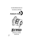
1
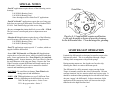
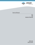
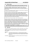
Auburn Gear, Inc.
LIMITED SLIP
DIFFERENTIAL
INSTALLATION
MANUAL
__________________________________
MH 553
LSI-2010-1
1
2
Ford Part Number: C8A219B546A
GM Part Number: 1052358
The Auburn Gear limited-slip differential design has been
extensively tested with high quality non-synthetic 80W90
hypoid oils treated with GM or Ford friction additives (3
oz. of additive will treat 1 quart of oil). To avoid differential
clutch chatter (noise) and for optimum performance, use the
oil and additive described above. Use of other additive and
oil types may cause differential clutch chatter.
-IMPORTANT LUBRICANT NOTE-
Once the differential has had bearings and/or a ring gear installed, it can no longer
b
id d
d h f
tb
h
df
If you feel that you have the wrong differential for your application, contact your
place of purchase and make the necessary arrangements to exchange the
differential for the correct one.
2. Check the differential flange position (bearing shoulder to flange face) to ensure
that it is correct. You may compare it to your old one. The differential flange
position depends only on the gear ratio that you are using. This flange position
may change at certain gear ratios. Some aftermarket ring gear and pinion sets
specify the differential case “series” that is required.
1. Ensure that your axle shaft mates with the differential side gear. Some models
have different spline counts depending on the year of manufacture.
Before installing the ring gear and pressing the bearings on to the differential, the
following two (2) items need to be checked:
-IMPORTANT APPLICATION NOTE-
PINION SHAFT MODIFICATION
CAUTION:
Certain 'C' clip axle applications with high gear ratios will require pinion shaft
modification due to the thickness of the ring gear. The thick ring gear will prohibit
the pinion shaft from being removed making 'C' clip installation impossible. Use
the following proceedure to modify the pinion shaft.
During installation of the axle shaft and 'C' washer, care
should be taken as not to pry against or on the spring retainer
plates. This may cause damage to the spring retainer.
1. Modification to be 90° to the pinion shaft lock screw hole as shown.
It is recommended that this be accomplished through grinding.
2. Remove sharp edge from modified section by buffing.
SPRING RETAINER
3. Pinion shaft should not be re-hardened after modification.
Reinstall the pinion shaft prior to installing the ring gear. With the ring gear
installed, rotate the pinion shaft so that the ground flat is parrallel to the ring
gear face. Pull the pinion shaft outward as far as possible. Install an axle
shaft and check that the end of the axle will pass the end of the pinion shaft.
An alternate solution is to index the ring gear on the differential until a tooth
space is directly in line with the pinion shaft. In many cases, this will allow
the pinion shaft to be removed without modification.
L
(L/2 - 0.10")
Lock screw hole
Ground surface
3
4
SPECIAL NOTES
-Ford 8” applications require the use of the following carrier
bearings:
LM 102949 (Bearing Cone)
LM 102910 (Bearing Cup)
Same bearings used in certain Ford 9” applications
-Ford 8” & Ford 9” applications require the use of ring gear
bolts from an open type differential, Ford Part Number D8024216-B. Ford limited-slip type bolts are too long.
Grind Here
.44
1.00
-Be sure to torque the pinion shaft lock screw to 20 – 25 lb-ft.
The lock screw is not torqued prior to shipment on most
models.
-Chrysler 8-3/4 applications require the use of the following
carrier bearings: (Stock bearing for 1969-’73 applications)
LM 104949 (Bearing Cone)
LM 104912 (Bearing Cup)
-Ford 7.5 applications require special ‘C’ washers, which are
supplied with the differential.
-Some AMC 20, Dana 44, and Chrysler 8-3/4 applications
require the use of an axle spacer, which is included with these
units. -Some applications use a Tone Wheel for the Anti-lock
braking system. In most instances, this Tone Wheel is fitted to
the outer diameter of the ring gear flange. Remove the Tone
Wheel from the original differential and install onto the new
differential. Refer to vehicle service manual for detailed
removal and installation procedures.
CAUTION: Be careful not to damage Tone Wheel teeth
during removal and installation.
NOTE: GM 7-5/8 applications use two (2) different Tone
Wheels, depending on the differential case series.
3.08:1 & down gear ratios—Series 2 case
3.23:1 & up gear ratios—Series 3
5
Chrysler 8-1/4 applications require modification
to the axle housing as shown to provide clearance
for the differential case. Clean housing after grinding.
LIMITED-SLIP OPERATION
Limited-slip differentials are designed to transfer torque to the
high traction wheel. This is accomplished through a torque
sensing clutch arrangement with preload springs.
During turning maneuvers, the clutches are forced to slip
allowing the wheels to rotate at different speeds.
The differential is a fully automatic torque sensing design.
Torque is instantly routed to the wheel with traction. In some
extreme situations, the low traction wheel may begin to spin. It
should be understood that spinning the low traction wheel faster
does not ‘engage’ the differential. In these situations, slight
application of the emergency brake will increase the torque
transferred to the high traction wheel.
6
INTRODUCTION
INSTRUCTIONS
There are two (2) items of concern when installing a
differential:
-Ring and Pinion Backlash
-Differential Carrier Bearing Preload
1. Raise and support vehicle.
These items are typically adjusted by means of shims or
threaded adjusters. The shims or adjusters will determine the
position of the ring gear, which determines the backlash of the
ring and pinion set. When installing a differential, the backlash
should be set to the original backlash setting, which was
measured prior to disassembly. To increase the backlash, adjust
the shim packs or threaded adjusters to move the ring gear
further away from the drive pinion gear. To decrease backlash,
move the ring gear closer to the drive pinion gear.
4. Remove axle shafts from housing.
2. Remove wheels and brake drums or brake rotors
3. Drain lubricant from carrier and remove cover.
A. ‘C’ clip axles
1. Remove pinion shaft lock screw and pinion shaft.
2. Push flanged end of axle shaft toward the center of
the housing and remove the ‘C’ clip from the button
end of the axle shaft. Repeat for other axle shaft.
3. Remove axle shafts from housing. Be careful not to
damage the oil seals.
Bearing preload refers to the amount of interference (press) fit
of the differential case and bearings into the carrier housing.
Adjust the bearing preload by adding or removing shim pack
thickness or by tightening or loosening the threaded adjusters.
Too much bearing preload will cause premature bearing failure.
Insufficient bearing preload will allow the differential to ‘walk’
in the housing causing damage to the ring and pinion set and
other components.
These instructions are intended as an aid for the experienced
automobile mechanic in properly installing the limited-slip
differential. It is expected that the installer be equipped with
the proper tools, equipment, and experience before attempting
the installation.
It is necessary to have an extensive selection of shims or
adjustable shim packs to properly install the differential.
Threaded adjuster applications do not require shims.
MAINTENANCE
It is recommended that the axle lubricant be changed every
7500 miles or as required by your vehicle’s service schedule.
Lubrication breakdown can lead to accelerated wear to all rear
axle components. See IMPORTANT LUBRICATION
NOTE on page 2 for oil and additive requirements.
7
B. Non-‘C’ clip axles
1. Remove axle shaft bearing retaining plate nuts and
remove the retaining plate.
2. Use a slide-hammer to remove the axle shafts. Be
careful not to damage the oil seals.
Note: Some axles use shims or adjuster nuts to set the
axle shaft end play. Refer to the vehicle service manual
for the proper removal and installation procedures for
the axle shafts.
5.
For removable carriers, disconnect the drive shaft from the
pinion yoke and remove the third member from the axle
housing.
6. Prior to further disassembly, measure and record the ring
and pinion backlash. Mount an indicator as shown in Figure
1. Hold the drive pinion stationary and rotate the ring gear
in both directions to measure the amount of backlash or free
play. Check the backlash at three to four points around the
ring gear and record for later use.
7. Mark bearing caps “R” and “L” to make sure that they will
be reassembled in their original position.
8
Figure 1
8. If equipped with adjuster nuts, remove adjuster nut locks
and loosen adjuster nuts.
-Chrysler tool C-4164
-Ford tool T70P4067-A
9. Remove bearing cap bolts and bearing caps.
10. Remove differential case. It may be necessary to use a pry
bar as shown in Figure 2. Exercise caution when prying on
the carrier so that the gasket sealing surface is not damaged.
Place shims/adjuster nuts and bearing cups with their
respective bearing cap.
Note: Adjuster nuts will stay in the housing in some axles.
11. Remove and discard the ring gear bolts. With a nonmetallic hammer or brass drift punch, drive the ring gear
loose from the differential case pilot and remove.
12. Remove anti-lock brake tone wheel if applicable. Consult
vehicle service manual for proper procedure.
9
Figure 2
13. Remove differential bearing cones from the differential
using the proper bearing puller and adapter. See Figure 3.
14. Clean all parts in a suitable cleaning solvent and dry
thoroughly. Clean axle housing by pushing a clean rag
through the axle tube with a wooden rod. Push the rag from
the end of the axle tube to the center of the axle housing.
Wipe down the inside of the housing with a clean rag.
CAUTION: Do not spin-dry the bearings with compressed
air. Serious injury may result.
15. Remove any burrs from all machined surfaces in the axle
housing, bearing cap and ring gear.
16. Inspect axle shaft bearing surface, bearings and seals.
Replace if needed.
17. Inspect differential bearings and replace if needed. Always
replace both the cup and cone as a set from the same
manufacturer.
10
Figure 3
18. Thoroughly clean the differential bearing hubs and ring gear
mounting flange prior to installation of the bearings and ring
gear.
19. Install the differential bearing cones onto the bearing hubs
of the differential case using the proper installation tool.
See Figure 4.
Note: Many Dana applications use shims between the
bearing cone and the differential case bearing hub shoulder.
The bearing cones must be removed to make adjustments to
the shim pack thickness.
20. For adjuster nuts, skip to Step 23.
21. Install differential with the bearing cups and shims into the
differential housing. Adjust the shim pack as necessary to
create a slip fit of the differential into the differential
housing. A slip fit is the thickest shim pack that can be
installed by hand with slight resistance. It will be necessary
to rotate the differential case after each shim thickness
change to seat the bearings.
11
Figure 4
22. Remove the differential from the differential housing.
Measure the combined thickness of the shims. This total
shim thickness is what is needed for installing the
differential (prior to adding preload to the bearings).
23. Heat the ring gear and anti-lock tone wheel (if applicable)
with a heat lamp or by submersing in hot water. Do not
exceed 300º F. Do not use a torch!
24. Install anti-lock tone wheel (if applicable) while hot onto the
outside diameter of the differential ring gear flange as stated
in the vehicle service manual.
25. Install the ring gear while hot onto the differential. It is
advantageous to use pilot studs to align the ring gear to the
differential as shown in Figure 5.
12
30. Rotate the differential case several revolutions to seat the
bearings. Check the backlash as described in Step 6.
31. Compare the backlash reading to the original reading taken
in Step 6 and adjust as needed. To increase backlash,
remove shim thickness from the ring gear side and add an
equal amount of shim thickness to the opposite side. To
decrease backlash, add shim thickness to the ring gear side
and remove an equal amount of shim thickness from the
opposite side.
Note: approximately .001” of shim equals .001” of
backlash.
Figure 5
26. Using new ring gear bolts, alternately tighten each ring gear
bolt to the proper torque:
3/8” Bolts = 50 lb ft
7/16” Bolts = 80 lb ft
1/2” Bolts = 100 lb ft
27. For adjuster nuts, skip to Step 35.
28. Select two shims of approximately equal size whose total
thickness is equal to the shim pack thickness determined in
step 21.
29. Place the differential assembly with the ring gear, bearing
cups and shims into the differential housing. Install bearing
caps and bolts in their proper position and tighten bolts.
While tightening bearing cap bolts, continuously rock the
ring gear back and forth to confirm backlash. If at any time
the backlash becomes reduced to zero, remove bearing caps
and adjust the shim packs by removing .010” from the ring
gear side and adding .010” to the opposite side. Repeat as
needed until both bearing caps can be torqued to the proper
torque value and ring and pinion backlash is confirmed.
13
32. Once the correct backlash reading has been established, add
.004” of shim thickness to both shim packs to preload the
differential bearings. It will be necessary to drive the shims
into position. Do not hit the bearing cups. It is
advantageous to use a Case Spreader to install the
differential.
33. Torque the bearing cap bolts to the proper value and rotate
the differential case several revolutions to seat the bearings.
Recheck the backlash and correct if necessary.
34. Skip to Step 47.
35. Place the differential assembly with ring gear and bearing
cups into the differential carrier.
36. Apply a light coat of axle oil to the bearings and adjuster nut
threads.
37. Install the bearing caps in their original position and hand
tighten the bearing cap bolts.
38. Install the adjuster nuts (unless still in the differential
housing) being careful not to cross thread the adjuster nuts
causing thread damage.
39. With the adjuster nuts installed and the bearings in position,
torque the bearing cap bolts to the proper torque value.
40. For Chrysler 8-1/4 & 9-1/4, skip to Step 46.
14
the LH adjuster nut the same amount. When making
adjustments, always make the final adjustment in the
tightening direction. For example, if the adjuster need to be
loosened one notch, loosen it two notches and tighten it one.
When the proper backlash has been established, install the
adjuster nut locks.
44. Install third member into axle housing using a new gasket or
silicone sealer and tighten nuts. Reinstall drive shaft.
45. Skip to Step 47.
46. For Chrysler 8-1/4 and 9-1/4 applications, using tool C4164, adjust the position of the differential until the proper
backlash reading has been established. Refer to Step 6 for
the backlash checking procedure and original backlash
reading. Alternately tighten each adjuster nut and rotate the
differential case several revolutions to seat the bearings.
Being careful not to change the backlash, repeat until each
adjuster nut has been tightened to 70 lb ft. Recheck
backlash and correct if necessary. Install adjuster nut locks.
Figure 6
41. Loose the RH adjuster nut (opposite the ring gear) until it is
away from the bearing cup. Tighten the LH adjuster nut
(ring gear side) until the ring gear is slightly forced into the
drive pinion (zero backlash). Rotate the differential several
revolutions to ensure no binding is present. Recheck RH
adjuster nut to be sure that it is not against the RH bearing
cup. Use an appropriate tool to turn adjuster nuts.
42. Install indicator as shown in Figure 6. Tighten RH adjuster
nut until a case spread of .008 - .012 is measured. Rotate
drive pinion several times in each direction to seat the
bearings and to be sure that binding does not occur. It may
be necessary to readjust the case spread by tightening the
RH adjuster nut.
43. Measure the backlash as done in Step 6. If necessary, adjust
the backlash until it matches the original reading taken in
Step 6. Increase backlash by loosening the LH adjuster and
tightening the RH adjuster the same amount. Decrease
backlash by loosening the RH adjuster nut and tightening
15
47. Install axle shafts into housing being careful not to damage
the oil seals.
A. ‘C’ clip axles
1. Remove pinion shaft lock screw and pinion shaft.
2. Push flanged end of axle shaft toward the center of
the housing and install the ‘C’ clip onto the button
end of the axle shaft. Pull axle shaft outward so the
shaft and washer seat in the counterbore of the side
gear. Repeat for other axle shaft.
3. Install pinion shaft through the case and pinions,
aligning the hole in the shaft with the lock screw
hole. Install lock screw and torque to 20 - 25 lb ft.
B. Non-‘C’ clip axles
1. Install axle shaft bearing retaining plate and nuts.
Tighten nuts to proper torque.
16
Note: Some axles use shims or adjuster nuts to set the
axle shaft end play. Refer to the vehicle service manual
for the proper removal and installation procedures for
the axle shafts.
48. Using a new gasket or silicone sealant, install axle cover and
tighten bolts.
49. Install brake drums or rotors.
50. Install wheels.
51. With the vehicle level, remove the fill plug and fill housing
to the proper level with the lubricant and additive
described on page 2.
52. Lower vehicle and test operation of axle.
FOR YOUR RECORDS
Differential Part Number:___________________
Purchased From:__________________________
Phone No.__________________________
Date Installed:____________________________
Installed By:_____________________________
Phone No._____________________________
Vehicle Mileage:__________________________
NOTES:
AUBURN GEAR, INC.
LIMITED-SLIP DIFFERENTIAL
LIMITED WARRANTY AND REMEDY
LIMITED WARRANTY
Auburn Gear, Inc. (“Manufacturer”) warrants that this product is free
from defects in materials and workmanship for a period of one (1)
year after purchase by the consumer, or 12,000 miles of normal use
by the consumer, whichever is less; provided that this product:
has been installed and maintained in accordance with the
Manufacturer’s instructions; and
has been used in regular automotive driving and not in any offroad application; and
has been used with the proper lubricant and additive, as specified
in the installation instructions at all times; and
has not been subject to modification, accident, or misuse.
This limited warranty is the sole express warranty provided by
manufacturer to the ultimate user of the product. The manufacturer
disclaims all other express warranties, and all implied warranties,
including the implied warranties of merchantability and fitness for a
particular purpose.
EXCLUSIVE REMEDY
In the event of a breach of this warranty, you shall return the
product to the seller within thirty (30) days after the expiration of
the limited warranty period, along with your proof of purchase
and explanation of the defect. Seller or Manufacturer may
investigate the claim of defect, and in the event of a defect in the
product shall, at their election, either repair the defective product,
replace the defective product with a new product, or refund the
purchase price. These remedies are your sole and exclusive
remedies in the event of a breach of warranty.
LIMITATION OF LIABILITY FOR DAMAGES
In no event shall Manufacturer be liable for consequential,
special, indirect, or exemplary damages, whether based upon tort,
contract, warranty, negligence, strict liability, or other legal
theory. Manufacturer’s liability shall be limited to direct
damages.
EXCEPTIONS TO LIMITED WARRANTY AND REMEDY
This limited warranty and remedy gives you specific legal rights.
You may have other statutory rights in states that do not allow the
limitation on or exclusion of certain warranties or remedies.
17
18
D-REX Program
Differential Replacement EXchange Program
Qualifications for the D-REX - Differential Replacement EXchange
Program1. In order to qualify; the unit manufactured date code must
be less than 4 years old OR one must submit the original dated
receipt of purchase. The date of purchase must be within the last 4
years. The date code is stamped on the differential case and will look
as such 018 A9 20 130 or just A9 20 130, the first 3 digits identify
the part number. In this example, 018=542018, the A9 identifies the
month and year, A=January and 9=1999, the 20 represents the 20
day of the month, disregard the 130. Hence, this unit was
manufactured on January 20, 1999 and would be applicable for the
replacement exchange program until January 20, 2003 OR 4 years
from the original purchase date. The original dated receipt should
only be submitted if the manufactured date code exceeds 4 years, but
the purchase date is less than 4 years. If the manufactured date
code is less than 4 years the original dated receipt is not needed to
validate the exchange. See the back for additional date code
explanation.
2. Contact your distributor (point-of-purchase) or Auburn Gear at
(260) 925 3200 x-328 or x-310 to get your Replacement Exchange
Number (RE#). Do not return your unit without getting this
number. In fact, units returned without RE# identification will be
returned to sender.
3. Fill out the Replacement Exchange Paperwork below. Attach the
address label to the outside of the box and indicate RE# as provided
by the distributor or Auburn Gear. In addition, place this form inside
the box in a ziplock style or plastic bag, along with the unit you are
requesting to be replaced. See the price for replacement on the back
side of this form. Note: a distributor may charge an additional
handling fee for administration of this program. Also, the distributor
may have a unit in stock, which will minimize the time required to get
the new replacement unit. In addition, do not send the differential
back with the bearings and/or ring gear installed. Auburn Gear
will not be held responsible for product that has these components
installed in fact, they will be scrapped.
Date Code Stamped Here
018 A9 20 130
or
018 A20 06
19
IMPORTANT:
HOLD ONTO THIS
DOCUMENT AND YOUR
ORIGINAL RECEIPT FOR
YOUR POSSIBLE FUTURE
USE!
Replacement Exchange Number
(RE#)____________________________________
Place of Purchase (Distributor Name):
_____________________________________
Name:________________________________________
Address:______________________________________
City:_________________ State:__________ Zip:______
Telephone #:(____)_______________
Email address:________________________
Note: Ship-to address as designated above must be the
same as the bill-to address, if different please send a
money order. Place this form on inside of box with unit. If
original date of receipt is required for qualification please
send it with this form.
Attn: D-REX Program
RE#________
400 East Auburn Drive
Auburn, IN 46706-3499 USA
20