1
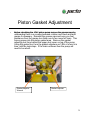
JP42
Pump Repair Manual
Service Manual – 2/10
1
JP42 Piston Pump
• Index
I d
Page
P
– Introduction………………….3
– Specifications…………...…..4
Specifications
4
– Piston Gasket Adjustment....5
– Parts breakdown……………6
breakdown
6
– Disassembly………………...8
– Assembly….………………...20
y
2
Introduction
The information in this manual is for the repair and
maintenance of the JP42 ceramic piston pump found
on the Jacto Arbus 200 airblast sprayer. The most
common problem you will find with this pump is the
piston gasket seals leaking usually caused by the
operator not properly lubricating the pistons every 4
hours or not adjusting the gasket adjuster. The
manual will also discuss the replacement procedure
for the bearings, shaft and other components.
Tools necessary:
1. ¾” wrench
2. 10mm wrench and socket
3. 13mm wrench and socket
4. Snap ring pliers
5. Flat blade screw driver
6. Bearing puller
7. Rubber Hammer
8. Inch pound and foot pound torque
wrenches
3
Specifications
•
•
•
•
•
•
•
Working
W
ki R
Rotation…………………………800rpm
t ti
800
Working Pressure………………………...500 psi
Power Consumption………………...……1.9 HP
Flow Rate……………………………….....11
Rate
11 GPM
Piston Quantity…………………………....3
Weight w/o oil…………...…………...…...48 lbs
Rotation
Rotation….....…....Clockwise
Clockwise or Counterclockwise
4
Piston Gasket Adjustment
•
Before rebuilding the JP42 piston pump remove the grease caps by
unthreading them in a counterclockwise rotation and check and add
grease if necessary. Reinstall the grease caps and once you feel
resistance from the grease turn them one to two more full turns. This
forces grease into the piston gasket area. Remove the gasket
adjusting tool from behind the upper dust cover on top of the pump.
Using the gasket tool, turn the gasket adjusters an 1/8th of a turn at a
time until the leak stops
time,
stops. If the leak continues then the pump will
need to be rebuilt.
Gasket Adjuster
Wrench
Gasket Adjuster
5
Parts Breakdown
6
Part Description
#
Description
#
Description
1
Suction Cover
28
Nut ½” UNC
2
Pump Head
29
Stud Bolt ½” – 13 UNC X 62mm
3
Pump Cover
30
Piston Assembly
4
Pump Valve
31
Connecting Rod Shaft
4A
Valve Packing
32
Connecting Rod Assembly
5
Seat Ring
33
Flat Washer 5.3 X 10.0 X 1.0mm
6
Gasket 30 X 39
34
Lock Washer M8
7
Compression Ring
35
Hex Bolt M8 X 35mm
8
Scraper Ring
36
Crankshaft
9
Gasket Adjuster
37
Fixed Bearing
10
Deflector Ring
38
Packing 620 X 920 X 4
11
Snap Ring (42)
39
Flange
12
Retainer
40
Crankshaft Protector
13
Lower Dust Guard
41
Hex Bolt M6 X 16 X 1.00
14
Upper Dust Guard
42
Male/Female Elbow 1
1” BSP 90
90°
15
Grease Nipple
43
Flat Washer 64 X 125 X 16
16
O-ring ORI-119
44
Flat Washer 41 X 127 X 12.1
17
Plug ¾ BSP
45
Bolt M4 X 12
18
Pump Body
46
Gasket Adjusting Tool
19
Packing 104 X 160 X 1.59
47
Identification Plate
20
Cover
48
Round Head Rivet
21
Bolt M6 X 1 X 20
49
Sticker “Keep oil on level”
22
Lock Washer M6
50
Compression Spring
23
Oil Sight ½” BSP with Seal
51
Guide Ring – Pump Valve
24
O-ring
O
ring OR1
OR1-112
112
52
Valve Packing
25
Drain Plug ¼” BSP
53
Valve Seat
26
Stud Bolt ½” UNC X 138mm
54
Disc 23mm
27
Lock Washer ½”
55
Valve Cage
7
Disassembly
•
Using a flat bladed
screwdriver remove the
upper dust cover.
•
Behind the dust cover you
will find the gasket
adjusting tool.
•
Remove the gasket
adjusting tool.
8
Disassembly
•
Using the gasket adjusting
tool, loosen all 3 gasket
adjuster as shown.
•
Using a ¾” wrench remove
tthe
e 2 bolts
bo ts tthat
at attach
attac tthe
e
cylinder head to the pump
body and remove the
cylinder head/valve cover
assembly.
Head Stud
•
Using the gasket adjuster
tool loosen the gasket
adjusters until they can be
removed by hand.
9
Disassembly
•
Remove the 3 gasket
adjusters with scraper ring.
•
Remove the scraper rings
from the 3 gasket
adjusters.
•
Remove all the
compression rings, their
gaskets and seat ring.
Note: Each compression
ring has 3 gaskets.
10
Disassembly
•
Remove the 3 grease caps
from the cylinder head by
turning them counterclockwise.
•
Using a ¾”
¾ wrench remove the
nuts that hold the valve covers
to the cylinder head.
•
Separate both valve covers
from the cylinder head as
shown.
11
Disassembly
•
Remove the 3 valves from
the outlet valve cover.
•
Remove the 3 intake
valves from the cylinder
head as shown.
12
Disassembly
•
•
Drain the oil from the
crankcase by removing the
drain plug on the oil pan.
Using a 10mm wrench
remove the bolts for the oil
pan as shown.
•
Remove the oil pan and
gasket from the pump
body.
•
Remove the plastic
crankshaft cover.
13
Disassembly
•
•
•
Remove the connecting
rod caps using a 13mm
socket and ratchet.
Note: If the connecting
rods and caps
p are to be
reused then make sure
they are assembled the
same way they came out.
Note: M
N
Make
k sure the
h
connecting rods and
caps are marked as pairs
as the connecting rods
and caps
p are machine
matched. Use a punch or
permanent marker to
mark the caps and rods
as sets. Note the
position where the
pistons were removed
from as they need to be
installed back in the
same position.
14
Disassembly
•
Using a 10mm wrench
remove the bolts for both
crankshaft bearing flanges.
•
Remove both crankshaft
bearing flanges and
gaskets.
•
Remove both the
crankshaft oil seals from
the crankshaft bearing
flanges.
15
Disassembly
•
Push the connecting rods
up away from the
crankshaft journals. Next
slide the crankshaft
assembly out of the pump
body as shown. Using a
hydraulic press or bearing
puller, replace the
crankshaft bearings if
necessary.
ecessa y
•
Remove the
piston/connecting rod
assembly from the pump
body by sliding it out the
bottom as shown.
•
Remove the connecting
rod wrist pin.
16
Disassembly
•
Using snap rings pliers
remove the snap ring from
the piston guide holes.
•
Remove the piston oil seal
from the piston guide holes
as shown.
17
Disassembly
•
Remove the oil fill/vent cap
from the pump housing by
unscrewing it.
•
Remove the o-ring for the
fill/vent cap and replace
with new one.
•
Remove the top portion of
the fill/vent cap as shown
by prying up gently
gently.
•
Check and clean the
fill/vent cap vent ports
inside the cap.
Reassemble the fill/vent
cap and reinstall back on
the pump body.
18
Disassembly
•
Remove the oil drain plug
from the bottom of the oil
pan.
•
Remove and replace the oil
drain plug o-ring.
•
Reinstall the oil drain plug.
Clean and check all components for wear or damage
and replace if necessary.
19
Assembly
•
Install the new oil seal into
the piston guide hole.
•
Using snap ring pliers
pliers,
install the snap ring into the
piston guide hole groove as
shown.
20
Assembly
•
Apply assembly lube onto
the wrist pin and
connecting rod hole and
assemble the connecting
rod to the piston with the
wrist pin,
•
Insert the connecting
rod/piston
d/ i
assembly
bl iinto
the proper piston guide
hole. Note: Make sure
the piston is going back
into the same hole it
came out of if reusing.
•
Push the pistons all the
way up into the piston
guide holes. Next insert
the crankshaft into the
pump body as shown.
21
Assembly
•
Install a new crankshaft oil
seals into the crankshaft
bearing flanges.
•
Using a new gasket
gasket, install
the crankshaft bearing
flange onto the pump body.
•
Install the crankshaft flange
bolts and using a inch
pound torque wrench and
10mm socket, tighten to 45
i /lb
in/lbs.
22
Assembly
•
Apply assembly lube on
both the rod caps and
crankshaft journals. Install
the connecting rod caps
onto the matching
connecting rod in the
proper order they were
originally removed.
•
Using a inch pound torque
wrench and a 13mm
socket, tighten to 160
in/lbs.
•
Install the crankshaft
plastic protector as shown.
23
Assembly
•
Using a new gasket
gasket, install
the oil pan onto the pump
body.
•
Using an inch pound torque
wrench and a 10mm
socket tighten the oil pan
bolts to 45 in/lbs.
24
Assembly
•
Insert 3 valves into the
cylinder head on the ports
opposite to the grease
reservoirs. Note: These
are the intake valves.
•
Insert 3 valves into the
valve cover that attaches to
the other side of the
cylinder head as shown.
Note: The valves should
be positioned to face in
the same direction (see
next page for illustration)
•
Assemble the valve covers
onto the cylinder head as
shown. Note the position
of the outlet port pointing
away from the pump
body
body.
Outlet Port
25
Assembly
•
Install the 2 nuts onto the
valve cover studs and
using a torque wrench and
¾” socket, tighten to 33
ft/lbs.
Pressure Side
Suction Side
Note: Diagram above is from a JP50 or 75 pump and for illustration purposes.
26
Seat Ring
Assembly
•
Apply a coating of grease
and assemble the seals for
the piston in the following
order: Seat ring, 3 piston
gaskets and compression
ring for each of the 3 piston
holes in the cylinder head
head.
Compression Ring
•
Tapered
Note the shape of the
piston gaskets and
compression ring.
ring The
tampered end of the
piston gasket goes
towards the taper on the
compression ring as
shown.
Piston Gasket
Tapered Side
•
Next, apply a coating of
grease and install the
scraper ring onto the
gasket adjuster with the
beveled edge pointing
towards the compression
ring and gaskets.
27
Assembly
•
Thread the gasket adjuster
with scraper ring attached
onto the cylinder head as
shown.
•
Using the gasket adjuster
tool thread the gasket
adjuster on very loosely.
Note: If you tighten the
gasket
k t adjusted
dj t d too
t
much at this point it
maybe difficult to install
the cylinder head onto
the pistons in the next
step.
28
Assembly
•
Install the cylinder
assembly onto the pump
body and pistons as
shown. Install the nuts that
hold the cylinder head to
the pump body and tighten
using a torque wrench and
¾” socket to 33 ft/lbs.
•
Using the gasket adjuster
tool slightly tighten the
gasket adjuster. Note:
Once the pump is
reinstalled onto the
sprayer it may be
necessary to readjust the
gasket adjuster, if a leak
occurs, by turning the
gasket adjuster an 1/8 of
a turn at a time clockwise
until the leak stops.
29
Assembly
•
Put the gasket adjuster tool
in its storage area under
the upper dust cover as
shown.
•
Install the upper dust cover
onto the pump body.
•
Install the 2 screws for the
upper dust cover and
tighten using a flat bladed
screwdriver.
30
Assembly
•
Remove the fill/vent cap on top
of the pump body.
•
Add approximately 1 quart of
SAE 30W oil or until the oil is
seen in the middle of the oil
level site glass located on the
oil pan. Reinstall the fill cap.
Fill Level
Oil Level Site
Glass
•
Remove the grease caps and
fill the reservoir cap ½ full with
a lithium based grease.
grease
Reinstall the caps and lightly
tighten until resistance from the
grease if felt then turn an
additional 1 to 2 turns.
Grease Cap
Grease Reservoir
31