1
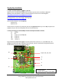
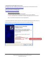
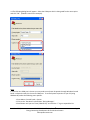
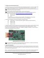
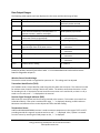
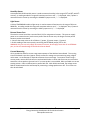
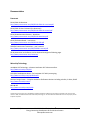
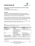
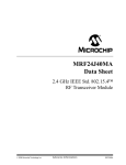
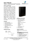
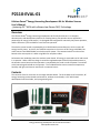
P2110-EVAL-01
Lifetime Power® Energy Harvesting Development Kit for Wireless Sensors
User’s Manual
- featuring PIC® MCU with eXtreme Low Power (XLP) Technology
Overview
The Lifetime Power® Energy Harvesting Development Kit for Wireless Sensors is a complete
demonstration and development platform for creating battery-free wireless sensor applications
powered by RF energy (radio waves). It is designed and configured for extremely low power operation,
and the firmware is pre-installed for out-of-the-box operation.
The wireless sensor boards are powered by the P2110 Powerharvester Receiver, which converts RF
energy into DC power. In this kit, the TX91501 transmitter is the source of RF energy at 915MHz, but
other sources from 850-950 MHz can also be used for power. The communications from the sensor
boards to the access point is 2.4GHz using 802.15.4-compliant radios.
No batteries are needed to power the wireless sensor board. RF energy is converted into DC and stored
in a capacitor. When sufficient charge is stored the regulated output of the P2110 provides power to
the wireless sensor board until the operation is completed by the node or until the power is turned off
at the low-voltage threshold on the capacitor. The included wireless sensors measure temperature,
humidity and light, and have an interface for an external sensor.
Contents
The contents of the kit are shown in the image and table below. The kit includes an RF transmitter, RF
energy harvesting receiver boards and antennas, wireless sensor boards, a PIC® MCU-based
development board and radio, and a programming tool.
Rev A.3 – 2012/11
P2110-EVAL-01: Lifetime Power®
Energy Harvesting Development Kit for Wireless Sensors
www.powercastco.com
Page 1
Qty
1
Item
Power and Data
Transmitter
(TX91501-3W-ID)
2
P2110 Evaluation Board
(P2110-EVB)
2
Patch antenna
2
Dipole antenna
2
Wireless Sensor Board
(WSN-EVAL-01)
1
Microchip 16-bit XLP
Development Board
(DM240311)
Microchip MRF24J40
PICtail/PICtail Plus
Daughter Board
(AC164134-1)
PICkit™ 3 programmer /
debugger
(PG164130)
1
1
Description
3-watt, 915 MHz transmitter for power and data with integrated 8dBi
antenna and two power jacks. Sends a pre-programmed transmitter
ID that is received by the P2110 Powerharvester component and is
decoded by the MCU on the Wireless Sensor Board
Evaluation board (Rev. B) for P2110 Powerharvester Receiver. This
board has an SMA connector to connect the antennas and a 10-pin
connector for the Wireless Sensor Board
915MHz directional antenna with 120-degree reception pattern
(included with the P2110 evaluation board)
915MHz omni-directional antenna with 360-degree reception
(included with the P2110 evaluation board)
Sensor for Temp/Humidity/Light and an external input. Plugs into
P2110 evaluation board, and sends data to the access point
(Microchip 16-bit XLP Development Board)
Development platform featuring Microchip’s PIC24F MCU that is preprogrammed to operate as an access point for receiving data from the
Wireless Sensor Boards. USB cable included in box.
2.4GHz, IEEE 802.15.4 radio that plugs into the 16-bit XLP
Development Board for receiving data from the Wireless Sensor
Boards
Programming tool for updating code on the Wireless Sensor Boards
and the 16-bit XLP Development Board. USB cable included in
package.
Set-up and Operation
Installation Overview
The following basis steps are required to operate the kit and are provided as an overview. Detailed
installation instructions are provided immediately after this summary.
1. Install HyperTerminal (already installed with Windows XP) or equivalent terminal emulator program.
2. Install the USB Serial Driver for the Microchip 16-bit XLP Development Board.
3. Configure HyperTerminal or equivalent terminal emulator program.
4. Connect antennas and sensor boards to P2110 evaluation board.
5. Turn on the transmitter and point toward receivers.
Note:
The required software for steps 1 and 2 above is available for download from
http://www.powercastco.com/resources/ or the direct links provided in the next section.
Rev A.3 – 2012/11
P2110-EVAL-01: Lifetime Power®
Energy Harvesting Development Kit for Wireless Sensors
www.powercastco.com
Page 2
Step-by-Step Installation
1. Install a terminall emulator program on your PC.
HyperTerminal is included with Windows XP and earlier version
versionss and no installation is required.
Windows Vista and Windows 7 users can download HyperTerminal
minal from the following link
http://www.powercastco.com/zip/HyperTerminal.zip
The download file is also found on the following page:
http://www.powercastco.com/resources/
There are only two files in this ZIP package:
hypertrm.dll
hypertrm.exe
Unzip the files to a location of your choice and click on hypertrm.exe when you are ready to operate the
program (not yet).. Be sure to keep these files in the same directory.
16-bit XLP Development Board as follows:
2. Verify the settings on the Microchip 16
S4:
PIC24FK
S7:
ON
J12
Jumper set to EXT PS/USB
JP6
Jumper on
JP9
Jumper on
JP10
Jumper on
Plug the Microchip MRF24J40 daughter board iinto the PICtail™ Connector, J7, of the XLP board. The
daughter board should hang off the side of the XLP board
board,, with the components facing inward/toward
the XLP board, as shown in the picture on page 11.
J12
Jumpers JP6, JP9, JP10
S7
S1
S4
J7
D3
S2
S1 – System Reset
S2 – Display last packet w/ timer update
Rev A.3 – 2012/11
P2110-EVAL-01: Lifetime Power®
Energy Harvesting Development Kit for Wireless Sensors
www.powercastco.com
Page 3
3. Download and install the USB-to-Serial driver file
The following driver file is needed to communicate with the Microchip 16-bit Development Board:
http://www.powercastco.com/zip/USB-Serial-Driver.zip
The file is also found on the following page:
http://www.powercastco.com/resources/
USB-to-Serial driver file installation
a. Download the file and unzip to a preferred location.
b. Connect the Microchip 16-bit Development Board to the PC using the USB cable
c. Manually install the driver as shown below. DO NOT use Windows automatic driver search.
Note – the installation example below is based on Windows XP
3.1 Connect the USB cable to the Microchip 16-bit XLP Development Board using min-USB connector J9.
When the following screen appears select “No, not at this time” and then click “Next”.
Select for MANUAL installation
Rev A.3 – 2012/11
P2110-EVAL-01: Lifetime Power®
Energy Harvesting Development Kit for Wireless Sensors
www.powercastco.com
Page 4
3.2 Select “Install from a list of specific location” and then click “Next” to continue.
3.3 Select the specific directory where you unzipped the USB-to-Serial driver files and then click “Next”.
Rev A.3 – 2012/11
P2110-EVAL-01: Lifetime Power®
Energy Harvesting Development Kit for Wireless Sensors
www.powercastco.com
Page 5
3.4 Click “Continue Anyway” to proceed.
3.5 When completed you should see this screen. Click “Finish” to proceed.
Rev A.3 – 2012/11
P2110-EVAL-01: Lifetime Power®
Energy Harvesting Development Kit for Wireless Sensors
www.powercastco.com
Page 6
4. Configure HyperTerminal to see data on the PC
The data can be displayed through a PC using any terminal emulator program. This manual will show
how to configure HyperTerminal, but the following settings are needed with any terminal emulator that
is used:
Baud rate:
19200 bps
Data bits:
8 bits
Parity:
None
Stop bits:
1 bit
Emulation:
ANSI or Auto Detect
Windows XP or Windows 2000
HyperTerminal is provided with Windows XP and earlier versions. To access the program use the
following menu options:
Start Menu > All Programs > Accessories > Communications > HyperTerminal
Windows Vista or Windows 7
Go to the directory where HyperTerminal was installed from Step 1 and double click on hypertrm.exe to
launch the program.
4.1 Upon starting the program the dialog box may ask you if you would like to make HyperTerminal your
default telnet program. Select Yes or No to proceed.
4.2 Next, you will be shown the following dialog box in which to enter a name for the connection. You
can choose any name, “Powercast” is used in this manual. Enter “Powercast” into the dialog box and
select “OK” to continue
Rev A.3 – 2012/11
P2110-EVAL-01: Lifetime Power®
Energy Harvesting Development Kit for Wireless Sensors
www.powercastco.com
Page 7
4.3 The following dialog box will appear. Select the COM port which is being used for the access point
and click “OK”. (COM16 is used in this example).
Note:
If more than one COM port is shown you may need to use System Properties through Windows Control
Panel to determine which is the correct COM port. To access System Properties on your PC (using
Windows XP) select the following menu options:
1. Start Menu > Control Panel > System
2. Click on the “Hardware” tab and then “Device Manager”
3. Scroll down until you see “Ports (COM & LPT)” and click the “+” sign to expand the list.
Rev A.3 – 2012/11
P2110-EVAL-01: Lifetime Power®
Energy Harvesting Development Kit for Wireless Sensors
www.powercastco.com
Page 8
4.4 Set the baud rate (Bits per second) to 19200 (19.2kbps) and click “OK”.
Use these default settings
4.5 The following blank screen will appear.
Packets are displayed automatically when the TX91501 transmitter or other RF energy source is
providing power to a P2110 evaluation board with the sensor board attached.
Rev A.3 – 2012/11
P2110-EVAL-01: Lifetime Power®
Energy Harvesting Development Kit for Wireless Sensors
www.powercastco.com
Page 9
4.6 Press switch S1 (see page 3) on the Microchip 16-bit XLP Development Board to reset the system
software and validate proper installation. If everything has been installed properly you will see the
following message displayed on the screen:
“Lifetime Power(R) Energy Harvesting Development Kit for Wireless Sensors”
“Powercast Corporation”
“Version X.X”
Switch Functions
Switches S1 and S2 on the Microchip 16-bit XLP Development Board function as defined below:
Switch S1
Resets the system software and all data buffers, including time counter and dT counter. Pressing S1 is
not required to start receiving packets and displaying sensor data.
Switch S2
Outputs data to the screen from the last packet received with an updated elapsed time and time
differential (dT).
Rev A.3 – 2012/11
P2110-EVAL-01: Lifetime Power®
Energy Harvesting Development Kit for Wireless Sensors
www.powercastco.com
Page 10
5. Configure the P2110 evaluation board
5.1 Attach an antenna to each P2110 evaluation board using SMA connector J1. The line-of-sight range
when using the included patch antennas is around 40 feet and around 20 for the dipole antenna.
Note: Operating the evaluation board on a ground plane such as an anti-static protection mat on a lab
bench may cause significant signal attenuation.
Note: Optional testing of P2110 Evaluation Board only (also requires Step 6).
To test the proper function of the P2110 Evaluation Board use the following settings or see the
instructions for the P2110-EVB at http://www.powercastco.com/PDF/P2110-EVB.pdf
J1:
Antenna connected
JP1:
C3 connected
S2:
LED
The LED will blink when sufficient power is available. The blinking rate is faster when
closer to the transmitter and slower when further from the transmitter.
5.2 Verify the configuration of the P2110 evaluation boards as follows:
JP1:
C5 connected (can also use C4 with a properly sized user-installed capacitor)
S2:
doesn’t matter
S3 :
doesn’t matter
S4 :
doesn’t matter
5.3 Attach the wireless sensor boards to the P2110 evaluation boards using the keyed connector and set
the sensor board node IDs (values of 0-7) as desired using the 3 position DIP switch (S1). Set the
jumpers on JP1 as appropriate for TEMP, LIGHT, HUMIDITY, EXTERNAL, and MODE. They should all be
connected for the default mode of operation.
WSN-EVAL-01 wireless sensor board
Note: JP2 can be used to measure current being used by the sensor board. It should be connected for
normal operation. This is explained in greater detail on page 14.
6. Plug in the Transmitter
Plug in the TX91501 Powercaster Transmitter and point it toward the P2110 evaluation boards with the
wireless sensor nodes. The line-of-sight range when using the included patch antennas is around 40-45
feet, and less for the dipole antenna.
Note – As a precaution, do not operate the transmitter within 12 inches of the evaluation board when
the patch antennas are attached. Please see the transmitter user’s manual for operating details.
Rev A.3 – 2012/11
P2110-EVAL-01: Lifetime Power®
Energy Harvesting Development Kit for Wireless Sensors
www.powercastco.com
Page 11
7. Verify Packet Reception
The sensor modules will transmit data when Vout of the P2110 is activated. Confirm packet reception
on the Microchip 16-bit Development Board by watching the LED D3. This LED will flash every time a
packet is received. The received data will also display on the PC as shown below.
The screen output for the two different modes of operation is shown below.
Mode 1 – MODE jumper is connected (default)
Mode 2 – MODE jumper is disconnected (future functionality or user’s code)
Mode 1 output
Mode 2 output
Rev A.3 – 2012/11
P2110-EVAL-01: Lifetime Power®
Energy Harvesting Development Kit for Wireless Sensors
www.powercastco.com
Page 12
Data Output Ranges
The following table explains each item displayed on the screen and the valid range of data.
Parameter
Packet#
Description
Packet counter (reset when S1 is pressed)
Time
Relative time counter (reset when S1 is pressed)
dT
Time differential between received packets. A
separate counter is used for each node
The ID number broadcasted by the TX91501
transmitter (factory programmed).
Wireless Sensor Board identifier*
00:00 (MM:SS) up to 99:59
Temp
Received Signal Strength Indicator – the received
signal strength from an RF power source
Temperature (Fahrenheit )
Humidity
Relative Humidity
Light
Ambient Illuminance (Lux)
Extrnl
External sensor reading
0.04 – 50 mW
“---“ otherwise
25 - 125°F
“---“ otherwise
15 – 85 % rh
“---“ otherwise
10 – 99999 lux
“---“ otherwise
0 – 3000mV
TX ID
Node
RSSI
Range
1 to 99999 – number is incremented
with each packet received
00:00:00 (HH:MM:SS) up to 99:59:59
1 – 254
“---“ otherwise (error)
0 – 7 (configured by DIP switches)
* If both wireless sensor boards are set to the same ID then the Time and dT values will be
based on packets received from either node. It is recommended that each wireless sensor
board is assigned a unique ID.
Wireless Sensor Board Voltage
The wireless sensor boards are regulated to operate at 3V. This voltage can’t be adjusted.
Transmitter Identification (TXID)
The TX91501 sends a unique identifier code along with the power that it outputs. This code can be used
for wireless sensor location tracking if devices are mobile. The wireless sensor board contains a circuit
for decoding this ID. If the wireless sensor board for some reason can’t read the ID, or there is no ID, it
sends an error code, and “---“ is displayed on the terminal.
Receiver Signal Strength Indicator (RSSI)
RSSI shows the actual power level that is being received at the antenna. This number is accurate from
0.04mW to 50mW. If the value is outside of the range, “---“ is displayed, denoting an RSSI read error.
Movement and reflections from various objects will affect the RSSI reading.
Temperature Sensor
A Murata NCP18XH103F03RB thermistor is used to measure temperature in the range of 25°F to 125°F.
A reading outside this range will constitute and error and “---“ is displayed. Also, if power is removed
from this sensor by removing the TEMP jumper on JP1, “---“ is displayed.
Rev A.3 – 2012/11
P2110-EVAL-01: Lifetime Power®
Energy Harvesting Development Kit for Wireless Sensors
www.powercastco.com
Page 13
Humidity Sensor
A Honeywell HIH-5030 humidity sensor is used to measure humidity in the range of 15% to 85%, with 3%
accuracy. A reading outside this range will constitute and error and “---“ is displayed. Also, if power is
removed from this sensor by removing the HUMIDITY jumper on JP1, “---“ is displayed.
Light Sensor
A Vishay TEMT6000X01 ambient light sensor is used to measure illuminance in the range of 10 lux to
99999 lux. A reading outside this range will constitute and error and “---“ is displayed. Also, if power is
removed from this sensor by removing the LIGHT jumper on JP1, “---“ is displayed.
External Sensor Port
The wireless sensor board has a terminal block (J3) for using external sensors. This port can supply
power to an external sensor, but the more power that the sensor uses, the longer the time period
between packets transmitted.
1. Connect the sensor wires to J3 as follows: (+) power, (S) sensor output, (-) ground.
2. Enable reading of the sensor port by connecting the EXTERNAL jumper pins on JP1.
WARNING: this port can only supply 3V to external sensors; do not apply more than 3V to EXTERNAL
port, as this will cause damage to the Wireless Sensor Board.
Current Measuring
JP2 is provided to allow for current usage measurements of the Wireless Sensor Board. The running
time of the board is too short (approx. 10ms) to allow for average current monitoring using a digital
multi-meter. An oscilloscope is required to witness the current usage. To measure current using a
current probe, remove JP2 and connect a test lead with hooks on either side from one pin to the other.
Attach the current probe to the test lead. If a current probe is not available, R18 is provided as a current
sensing resistor. R18 is a 10Ω resistor in parallel with JP2. With JP2 disconnected, the voltage across
R18 can be witnessed on the oscilloscope by connecting a voltage probe across JP2. The current can
then be calculated.
Rev A.3 – 2012/11
P2110-EVAL-01: Lifetime Power®
Energy Harvesting Development Kit for Wireless Sensors
www.powercastco.com
Page 14
Software
Firmware source code
The source code for the Wireless Sensor Board and Access Point (Microchip XLP 16-bit Development
Board) is available for download from the Powercast website
http://www.powercastco.com/resources/
Software for Microchip’s MiWi™ protocol is included as part of Powercast’s code and is subject to
accepting Microchip’s MiWi™ Software License Agreement before download.
All software pre-loaded in the kit components or available for download is subject to Powercast’s
Limited Warranty for Development Systems.
Modifying the firmware on the Wireless Sensor Boards or Access Point
The software on the Wireless Sensor Boards and the Access Point can be modified using Microchip’s free
MPLAB® Integrated Development Environment (IDE). Programming is done using the C programming
language.
Download MPLAB IDE from Microchip Technology Inc.
Use the link below and follow Microchip’s instructions for installation and operation.
http://www.microchip.com/mplab
PICkit 3 Programmer/Debugger
The PICkit 3 programming tool is included to re-program the wireless sensors boards and the access
point.
Wireless sensor board: use header J1, enable “Power target circuit from PICkit 3” checkbox
(found under Programmer menu Settings… Power tab)
16-bit XLP board:
use header J5, disable “Power target circuit from PICkit 3” checkbox
HyperTerminal
HyperTerminal is available for download at the following link:
http://www.powercastco.com/zip/HyperTerminal.zip
USB-to-Serial Driver
The USB-to-Serial driver for the Microchip 16-bit XLD Development Board is available at the following
link:
http://www.powercastco.com/zip/USB-Serial-Driver.zip
Rev A.3 – 2012/11
P2110-EVAL-01: Lifetime Power®
Energy Harvesting Development Kit for Wireless Sensors
www.powercastco.com
Page 15
Documentation
Powercast
P2110-EVAL-01 Overview
http://www.powercastco.com/PDF/P2110-EVAL-01-overview.pdf
P2110-EVAL-01 User’s Manual (this document)
http://www.powercastco.com/PDF/P2110-EVAL-01-manual.pdf
P2110 Powerharvester Receiver – datasheet
http://www.powercastco.com/PDF/P2110-datasheet.pdf
P2110 Evaluation Board – instructions
http://www.powercastco.com/PDF/P2110-EVB.pdf
TX91501 Powercaster Transmitter – user’s manual
http://www.powercastco.com/PDF/TX91501-manual.pdf
All documentation and software can be obtained through the following page:
http://www.powercastco.com/resources/
Microchip Technology
nanoWatt XLP Technology – eXtreme Low Power PIC® Microcontrollers
http://www.microchip.com/XLP
XLP 16-bit Development Board – for low power PIC® MCU prototyping
http://www.microchip.com/xlp16bitboard
Wireless Design Center – Complete hardware & software solutions including sub-GHz, 2.4GHz, & WiFi
http://www.microchip.com/rf
MPLAB IDE
http://www.microchip.com/mplab
The Microchip name and logo, PIC, and MPLAB are registered trademarks of Microchip Technology Incorporated in the U.S.A and other
countries. MiWi, and PICkit are trademarks of Microchip Technology Inc. All other trademarks mentioned herein are the property of their
respective companies.
Rev A.3 – 2012/11
P2110-EVAL-01: Lifetime Power®
Energy Harvesting Development Kit for Wireless Sensors
www.powercastco.com
Page 16
Mouser Electronics
Authorized Distributor
Click to View Pricing, Inventory, Delivery & Lifecycle Information:
Powercast:
P2110-EVAL-01