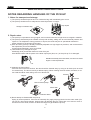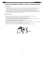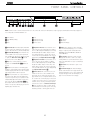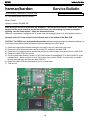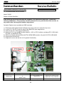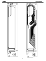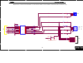
1
harman kardon
Model DVD
22
DVD/CD/CD-R/CD-RW/VCD MP3 Player
Service Manual
- Contents SERVICE PRECAUTIONS………………….……2
BULLETIN HK2004-03……………….………….18
SPECIFICATIONS…………………………..…….5
BULLETIN HK2005-02……………….………….20
FRONT PANEL CONTROLS………….………….6
TECH TIP HKTT2005-01………………………..21
INFORMATION DISPLAY…………….…….…….7
ELECTRICAL PARTS LIST………….………….22
REMOTE CONTROL………………………..…….8
MECHANICAL PARTS LIST…………………….29
REAR PANEL CONNECTIONS……………..….10
SEMICONDUCTOR PINOUTS………………….31
INSTALLATION/CONNECTIONS……….……….11
PCB DRAWINGS…………………………………38
BASIC TROUBLESHOOTING GUIDE….…..….15
SYSTEM CONFIGURATION SPECS………….47
RESET INSTRUCTIONS………………………...15
SCHEMATICS…………………………..………..48
EXPLODED VIEW/PARTS LIST.…………….…16
PACKAGE…………..………………..…….……..61
BLOCK DIAGRAM.……………..……………..…17
harman/kardon, Inc.
250 Crossways Park Dr.
Woodbury, New York 11797
Rev4
5/2005
DVD22
harman/kardon
SERVICING PRECAUTIONS
NOTES REGARDING HANDLING OF THE PICK-UP
1. Notes for transport and storage
1) The pick-up should always be left in its conductive bag until immediately prior to use.
2) The pick-up should never be subjected to external pressure or impact.
Drop impact
Storage in conductive bag
2. Repair notes
1) The pick-up incorporates a strong magnet, and so should never be brought close to magnetic materials.
2) The pick-up should always be handled correctly and carefully, taking care to avoid external pressure and
impact. If it is subjected to strong pressure or impact, the result may be an operational malfunction
and/or damage to the printed-circuit board.
3) Each and every pick-up is already individually adjusted to a high degree of precision, and for that reason
the adjustment point and installation
screws should absolutely never be touched.
4) Laser beams may damage the eyes!
Absolutely never permit laser beams to enter the eyes!
Also NEVER switch ON the power to the laser output part (lens, etc.) of the pick-up if it is damaged.
NEVER look directly at the laser beam, and don’t let contact
fingers or other exposed skin.
5) Cleaning the lens surface
If there is dust on the lens surface, the dust should be cleaned away by using an air bush (such as used
for camera lens). The lens is held by a delicate spring. When cleaning the lens surface, therefore, a cotton swab should be used, taking care not to distort this.
Pressure
Magnet
Pressure
How to hold the pick-up
Cotton swab
Conductive Sheet
6) Never attempt to disassemble the pick-up.
Spring by excess pressure. If the lens is extremely dirty, apply isopropyl alcohol to the cotton swab. (Do
not use any other liquid cleaners, because they will damage the lens.) Take care not to use too much of
this alcohol on the swab, and do not allow the alcohol to get inside the pick-up.
2
1
DVD22
harman/kardon
NOTES REGARDING COMPACT DISC PLAYER REPAIRS
1. Preparations
1) Compact disc players incorporate a great many ICs as well as the pick-up (laser diode). These components are sensitive to, and easily affected by, static electricity. If such static electricity is high voltage,
components can be damaged, and for that reason components should be handled with care.
2) The pick-up is composed of many optical components and other high-precision components. Care must
be taken, therefore, to avoid repair or storage where the temperature of humidity is high, where strong
magnetism is present, or where there is excessive dust.
2. Notes for repair
1) Before replacing a component part, first disconnect the power supply lead wire from the unit
2) All equipment, measuring instruments and tools must be grounded.
3) The workbench should be covered with a conductive sheet and grounded.
When removing the laser pick-up from its conductive bag, do not place the pick-up on the bag. (This is
because there is the possibility of damage by static electricity.)
4) To prevent AC leakage, the metal part of the soldering iron should be grounded.
5) Workers should be grounded by an armband (1MΩ)
6) Care should be taken not to permit the laser pick-up to come in contact with clothing, in order to prevent
static electricity changes in the clothing to escape from the armband.
7) The laser beam from the pick-up should NEVER be directly facing the eyes or bare skin.
Armband
Resistor
(1 Mohm)
Resistor
(1 Mohm)
Conductive
Sheet
3
2
DVD22
harman/kardon
ESD PRECAUTIONS
Electrostatically Sensitive Devices (ESD)
Some semiconductor (solid state) devices can be damaged easily by static electricity. Such components commonly are called Electrostatically Sensitive Devices (ESD). Examples of typical ESD devices are integrated circuits and some field-effect transistors and semiconductor chip components. The following techniques should
be used to help reduce the incidence of component damage caused by static electricity.
1. Immediately before handling any semiconductor component or semiconductor-equipped assembly, drain off
any electrostatic charge on your body by touching a known earth ground. Alternatively, obtain and wear a
commercially available discharging wrist strap device, which should be removed for potential shock reasons
prior to applying power to the unit under test.
2. After removing an electrical assembly equipped with ESD devices, place the assembly on a conductive surface such as aluminum foil, to prevent electrostatic charge buildup or exposure of the assembly.
3. Use only a grounded-tip soldering iron to solder or unsolder ESD devices.
4. Use only an anti-static solder removal device. Some solder removal devices not classified as "anti-static"
can generate electrical charges sufficient to damage ESD devices.
5. Do not use freon-propelled chemicals. These can generate electrical charges sufficient to damage ESD
devices.
6. Do not remove a replacement ESD device from its protective package until immediately before you are
ready to install it. (Most replacement ESD devices are packaged with leads electrically shorted together by
conductive foam, aluminum foil or comparable conductive materials).
7. Immediately before removing the protective material from the leads of a replacement ESD device, touch the
protective material to the chassis or circuit assembly into which the device will by installed.
CAUTION : BE SURE NO POWER IS APPLIED TO THE CHASSIS OR CIRCUIT, AND OBSERVE ALL
OTHER SAFETY PRECAUTIONS.
8. Minimize bodily motions when handing unpackaged replacement ESD devices. (Otherwise harmless motion
such as the brushing together of your clothes fabric or the lifting of your foot from a carpeted floor can generate static electricity sufficient to damage an ESD device).
4
3
DVD22
harman/kardon
DVD 22 TECHNICAL SPECIFICATIONS
Applicable Disc:
Disc formats: 5-inch (12cm) or 3-inch (8cm) DVD-Movie, Standard conforming DVD-R, DVD+R, DVD-RW, DVD+RW,
VCD, CD, CD-R, MP3 or CD-RW discs
Region code: DVD Movie disc with Code 1 or 0 only
DVD-Layers: Single Side/Single Layer, Single Side/Dual Layer, Dual Side/Dual Layer
Audio formats: Linear PCM, MPEG, Windows Media 9, Dolby Digital or DTS Audio Discs
Still image format: JPEG
Video Signal System:
NTSC
Composite Video Output:
1V p-p/75 ohms, sync negative polarity
S-Video Output:
Y/Luminance: 1V p-p/75 ohms, sync negative polarity
C/Chrominance: 0.286V p-p
Component Video Output:
Y: 1V p-p/75 ohms, sync negative polarity
Pr: 0.7V p-p/75 ohms
Pb: 0.7V p-p/75 ohms
Analog Audio Output:
2V rms max
Frequency Response:
DVD (Linear PCM):
CD:
2Hz – 22kHz +0/–0.5dB (48kHz sampling)
2Hz – 44kHz +0/–0.5dB (96kHz sampling)
2Hz – 20kHz +0/–0.5dB
Signal/Noise Ratio (SNR):
105dB (A-weighted)
Dynamic Range:
DVD: 100dB (18-bit)/105dB (20-bit)
CD/DVD: 96dB (16-bit)
THD/1kHz:
DVD/CD: 0.0025%
Wow & Flutter:
Below Measurable Limits
AC Power:
110–2400VAC/50–60Hz
Power Consumption:
2 Watts (On/Standby)/20 Watts (Max)
Dimensions (W x H x D):
17-3/10" x 1-15/16" x 12" (440mm x 49mm x 330mm)
Weight:
7.3 lb (3.3kg)
Depth measurement includes knobs and connectors.
Height measurement includes feet and chassis.
All specifications subject to change without notice.
Harman Kardon and Power for the Digital Revolution are registered trademarks of Harman International Industries, Incorporated.
*Dolby is a registered trademark of Dolby Laboratories Licensing Corporation. Manufactured under license from Dolby Laboratories. “Dolby”, “Pro Logic” and the
double-D symbol are registered trademarks of Dolby Laboratories. Confidential Unpublished Works. 1992-1997 Dolby Laboratories, Inc. All rights reserved.
“DTS” is a registered trademark of Digital Theater Systems, Inc.
Windows Media is a registered trademark of Microsoft Corporation in the United States and/or other countries.
This product incorporates copyright protection technology that is protected by method claims of certain U.S. patents and other intellectual property rights owned by
Macrovision Corporation and other rights owners. Use of this copyright protection technology must be authorized by Macrovision Corporation and is intended for home
and other limited viewing uses only unless otherwise authorized by Macrovision Corporation. Reverse engineering or disassembly is prohibited.
5
DVD22
harman/kardon
FRONT-PANEL CONTROLS
NOTE: To make it easier to follow the instructions that refer to the controls and connectors in this illustration, a larger copy may be downloaded from the Product Support section for this product at www.harmankardon.com.
Power Indicator
1 Power On/Off (Standby)
2 Play
3 Pause
4 Stop
5 Skip/Search Reverse
6 Skip/Search Forward
7 Remote Sensor
8 Display
9 Disc Drawer
! Open/Close
@ Information Display
1 Power Indicator: This indicator lights amber when
the unit is connected to an AC power source, but is not
turned on. When the unit is on, the indicator lights blue.
6 Skip/Search Reverse: Press this button once to
return to the start of the current chapter for a DVD or
track for a CD. Subsequent individual presses will skip
backwards through the available chapters or tracks.
Press and hold the button to play the disc in the fast
reverse mode at the speed indicated in the on-screen
display and by the Playback Mode Indicators K.
8 Display: Press this button to reduce the brightness of the Information Display by 50% or to turn the
display off completely in the following order: FULL
BRIGHTNESS ➔ HALF BRIGHTNESS ➔ OFF ➔
FULL BRIGHTNESS.
1 Power On/Off (Standby): Press the button once
to turn the DVD 22 on. Press it again to put the unit
in the Standby mode. Note that in order for this switch
to operate, the Main Power Switch must be
pressed in so that it is in the ON position.
2 Play: Press to initiate playback or to resume
playback after the Pause Button 4C has been
pressed.
3 Pause: Press this button to momentarily pause
playback. To resume playback, press the button again.
If a DVD is playing, action will freeze and a still picture
will be displayed when the button is pressed.
4 Stop: Press this button once to place the disc in
the Resume mode, which means that playback will
stop, but as long as the tray is not opened or the disc
changed, DVD playback will continue from the same
point on the disc when the Play Button 2G is
pressed again. Resume will also work if the unit was
turned off. To stop a disc and have play start from the
beginning, press the button twice.
7 Skip/Search Forward: Press this button once to
move to the start of the next chapter for a DVD or
track for a CD. Subsequent presses will skip forward
through the available chapters or tracks. Press and
hold the button to play the disc in the Fast Play mode
at the speed indicated in the on-screen display and by
the Playback Mode Indicators K.
8 Remote Sensor: The sensor that receives commands from the remote control is behind the front
panel in this area. To ensure proper operation of the
player with the remote, it is important that this area not
be covered. In the event that the player is enclosed in
a cabinet or if the remote sensor is covered, you may
extend the remote sensor by connecting an optional,
external remote sensor to the Remote Control Input
• on the rear panel (see page 11). When optional,
external IR “blasters” are used for system control, they
should be positioned so that they point at this area.
6
) Disc Drawer: This drawer is used to hold the
discs played in the unit. Be certain to seat all discs
carefully within the recess in the drawer. Do not press
down on the drawer when it is open, to avoid damage
to the player.
! Open/Close: Press this button to open or close
the disc tray.
@ Information Display: The Information Display
provides status information on the player and the disc
being played through a series of specific indicators and
messages that appear in the dot matrix display. See
page xx for more information on the display.
FRONT-PANEL CONTROLS
7
DVD22
harman/kardon
FRONT-PANEL INFORMATION DISPLAY
NOTE: To make it easier to follow the instructions that refer to the controls and connectors in this illustration, a larger copy may be downloaded from the Product Support
section for this product at www.harmankardon.com.
A Disc-Type Indicators
B Program Indicator
C Random Indicator
D Repeat Indicators
E VCD Playback Control Indicator
F A-B Repeat Indicator
G V-OFF Indicator
H Angle Indicator
I Parental Lock Indicator
J Progressive Indicator
K Playback-Mode Indicator
L Title Indicators
M Chapter/Track Number Indicators
N Time Indicators
A Disc Type Indicators: The DVD, CD, VCD, MP3,
WMA or JPEG indicator will light to show the type of
disc currently being played.
I Parental Lock Indicator: This indicator lights
when the parental-lock system is engaged in order to
prevent anyone from changing the rating level without
a code.
M Chapter/Track Number Indicators: When a
DVD disc is playing, these two positions in the display
will show the current chapter. When a CD disc is playing they will show the current track number.
J Progressive Scan Indicator: This indicator lights
when the unit sends out a progressive scan signal.
N Time Indicators: These positions in the indicator
will show the running time of a DVD in play. When a
CD is playing, these indicators will show the current
track time, time remaining in the current track, or the
total remaining time on the disc.
B Program Indicator: This indicator lights when the
programming functions are in use.
C Random Indicator: This indicator lights when the
unit is in the Random Play mode.
D Repeat Indicators: These indicators light when
any of the Repeat functions are in use.
E VCD Playback Control Indicator: This indicator
lights when the playback control function is turned on
with VCDs.
F A-B Repeat Indicator: This indicator lights when
a specific passage for repeat playback has been
selected.
G V-OFF Indicator: This indicator lights in red when
the unit's video output has been turned off by pressing
the V-OFF button on the remote control.
H Angle Indicator: This indicator blinks when
alternative viewing angles are available on the
DVD currently playing.
8
K Playback-Mode Indicators: These indicators
light to show the current playback mode:
› Lights when a disc is playing in the normal mode.
››› When the DVD 22 is in the Fast Search play
mode, two or three of these indicators will light to
show that the unit is in a Fast Play mode, depending
on the speed.
± Lights when the disc is paused.
‹‹ Lights when the disc is in the Fast Search
Reverse mode.
L Title Indicators: These two positions in the display will show the current title number when a DVD
disc is playing.
FRONT-PANEL INFORMATION DISPLAY
7
NOTE: The indicators LMN will also display text
messages about the DVD’s status, including Reading
when a disc is loading, Standby when the unit is
turned off, and Disc Error when a disc not compatible
with the DVD is put into the play position.
DVD22
harman/kardon
REMOTE CONTROL FUNCTIONS
0 Power On
1 Playlist
2 Audio Select
3 Open/Close
4 ⁄/¤/‹ / › Navigation Buttons
5 Info
6 Pause
7 Play
8 Previous Step/Skip
9 Search/Slow Reverse
A Stop
B Video Off
C Display
D Title
E Clear
F Numeric Keys
G Light
H A-B Repeat
I Angle
J Zoom
K Picture –/+
L Search/Slow Forward
M Next Step/Skip
N Status
O Disc Menu
P Enter
Q OSD
Subtitle
Off
Random
Repeat
IR Emitter
NOTE: To make it easier to follow the instructions that refer to the controls and connectors in this illustration, a larger copy may be downloaded from the Product Support
section for this product at www.harmankardon.com.
8
REMOTE CONTROL FUNCTIONS
9
DVD22
harman/kardon
REMOTE CONTROL FUNCTIONS
0 Power On: Turns on the player when it is in
Standby mode (Harman Kardon logo appears onscreen).
1 Playlist: Press this button to change the order in
which tracks are played on a CD or chapters are
played on a DVD. (See page 28 for more information
on creating and playing playlists.)
2 Audio Select: Press to access various audio languages on a DVD (If the DVD contains multiple audio
streams).
3 Open/Close: Press to open or close the disc
tray.
4 M NKL Navigation Buttons: Use to move
the cursor in the OSD.
5 Info: Press once for detailed informations on the
disc playing (Video/Audio Bit rate, Movie aspect ratio
and others). Press again to remove information from
screen.
6 Pause: Press this button to pause the disc and
freeze the picture during DVD or VCD playback, or to
pause the playback of a CD. To play a DVD in the fast,
slow or forward mode, first press this button and then
press either the Search/Slow Forward L or
Reverse 9 button.
7 Play: Press this button to begin the playback of a
disc, or to resume the playback when a disc has been
paused.
8 Previous Step/Skip: Press this button once to
skip back to the beginning of the current chapter on a
DVD or track on a CD. Press it again to continue to
skip back through the remaining chapters or tracks.
After first pressing the Pause button 6, press this
button to step backwards through a DVD as a series of
still image frames. Press it again to continue to skip
back through the remaining previous chapters.
9 Search/Slow Reverse: This button initiates fast
or slow play in the reverse mode. For fast reverse play,
each press of the button when playing DVD discs
changes the speed as indicated by the number of leftfacing arrows appearing in the upper right corner of
the screen and in the Playback Mode Indicators
K. For slow reverse play, first press the Pause button
6 and the each subsequent press of this button
will change the slow play speed as indicated by the
number of left-facing arrows appearing in the upper
right corner of the screen and in the Playback Mode
Indicators K.
A Stop: When a DVD is playing, press this
button once to place the disc in the Resume mode,
which means that playback will stop. However, as long
as the disc drawer is not opened DVD playback will
continue from the point where the disc was stopped
when the Play button 73 is pressed again.
10
Pressing the button twice will stop the disc and play
will start from the beginning of the disc when the Play
button 73 is pressed again. During CD playback
press this button to stop playback.
B Video Off: Press this button to turn off the video
output for improved audio performance when playing
CDs. Press it again to view the on-screen menus.
C Display: Press to change the brightness of the
front panel display or to turn the display off completely
in the following order: FULL BRIGHTNESS ➜ HALF
BRIGHTNESS ➜ OFF ➜ FULL BRIGHTNESS
D Title: When a DVD is playing, press this button
to go back to the main title menu for the disc being
played.
E Clear: Press this button to remove on-screen
menus or banners from the display screen.
F Numeric Keys: Press these buttons to enter a
number.
G Light: Press to illuminate remote controller.
H A-B Repeat: Press this button to enter the starting point of a sequence on a disc you wish to repeat.
The second press enters the end of the selection to
be repeated. Once the “A” (start) and “B” (end) points
have been entered the player will repeat the selection
until the Play button 73 is pressed or the disc is
stopped.
M Next Step/Skip: Press this button once to
advance to the beginning of the next chapter on a
DVD or track on a CD. Press it again to continue to
advance through the available chapters or tracks. After
first pressing the Pause button 6, press this button
to step through a DVD as a series of still image
frames.
N Status: Press while a disc is playing to view
banner display. Use the M NKL Navigation
buttons 4 to move through the different features
in the Banner Display. When a symbol is highlighted,
press ENTER P on the remote to select it.
O Disc Menu: While a DVD is playing, press this
button to view the disc’s main navigation menu.
P Enter: Press this button to enter a setting to the
player’s menu or to confirm a menu selection choice
on a disc’s on-screen menu.
Q OSD: Press this button to use the on-screen
menu system to adjust the player’s configuration
settings or to build a playlist.
Subtitle: When a DVD is playing, press to select
a subtitle language or to turn subtitles off.
Off: Turns off the player to standby mode.
Random: Press this button to play the tracks
on a CD, MP3, WMA or JPEG disc in random order.
I Angle: Press this button to change the angle on
discs programmed for multiple angle views.
Repeat: Press this button to view the Repeat
Menu that allows you to change the playback mode
to repeat a chapter or track or the entire disc.
J Zoom: Press this button to zoom in on the
image from a DVD, VCD or JPEG image. The image
may be expanded by a factor of x2, x3, x4 or x5.
Once the on-screen indication of the zoom ratio leaves
the screen you may use the Navigation buttons 4
to move the picture across the screen.
IR Emitter: This small, clear button-like device
sends the IR commands from the remote control to
the DVD 22. To ensure proper performance of the
remote control, be sure to point it toward the unit and
do not cover it with your fingers when sending remote
commands.
K Picture –/+: Press these buttons to move to the
next (+) or previous (–) image when playing a disc
with JPEG images.
L Search/Slow Forward: This button initiates fast
or slow play in the forward mode. For fast forward play,
each press of the button when playing DVD discs
changes the speed as indicated by the number of
right-facing arrows appearing in the upper right corner
of the screen and in the Playback Mode Indicators
K. For slow forward play, first press the Pause
button 6 and the each subsequent press of this
button will change the slow play speed as indicated
by the number of right-facing arrows appearing in the
upper right corner of the screen and in the Playback
Mode Indicators K.
REMOTE CONTROL FUNCTIONS
9
DVD22
harman/kardon
REAR-PANEL CONNECTIONS
NOTE: To make it easier to follow the instructions that refer to the controls and connectors in this illustration, a larger copy may be downloaded from the Product Support
section for this product at www.harmankardon.com.
¡ Optical Digital Output
™ Coaxial Digital Output
£ Analog Audio Outputs
¢ S-Video Output
∞ Component Video Outputs
§ Composite Video Output
¶ Remote Control Output
• Remote Control Input
ª AC Power Cord
¡ Optical Digital Output: Connect this jack to the
optical digital input of an A/V receiver or surround
processor for Dolby Digital, DTS or PCM audio
playback.
∞ Component Video Outputs: These outputs carry
the component video signals for connection to display
monitors with component video inputs. For standard
analog TVs or projectors with inputs marked Y/Pr/Pb
or Y/Cr/Cb, connect these outputs to the corresponding inputs. If you have a high-definition television
or projector that is compatible with high-scan-rate
progressive video, connect these jacks to the HD
component inputs. If you are using a progressive scan
display device, PROGRESSIVE must be
selected in the Video menu in order to take advantage
of the progressive scan circuitry. See “Scan Type”
section on page 20 for more information on progressive
scan video.
• Remote Control Input: Connect the output of a
remote infrared sensor, or the remote control output of
another compatible Harman Kardon product, to this
jack. This will enable the remote control to operate
even when the front-panel Remote Sensor on the
DVD 22 is blocked. This jack may also be used with
compatible IR remote control-based automation systems.
™ Coaxial Digital Output: Connect this jack to the
coaxial digital input of an A/V receiver or surround
processor for Dolby Digital, DTS or PCM audio
playback.
NOTE: The coaxial digital output should only be connected to a digital input. Even though it is the same
RCA-type connector as standard analog audio connections, DO NOT connect it to a conventional analog
input jack.
£ Analog Audio Outputs: Connect these jacks to
an audio input on an A/V receiver or surround processor for analog audio playback.
¢ S-Video Output: Connect this jack to the S-Video
input on a television or video projector, or to an SVideo input on an A/V receiver or processor if you are
using that type of device for S-Video input switching.
ª AC Power Cord: Connect this plug to an AC outlet. If the outlet is controlled by a switch, make certain
that it is in the ON position.
NOTE: You’ll find more details about all audio/video
connections under Setup and Connections on the
following pages.
IMPORTANT: These jacks should NOT be connected
to standard composite video inputs.
§ Composite Video Output: Connect this jack to
the video input on a television or video projector, or to
a video input on an A/V receiver or processor if you
are using that type of device for video input switching.
¶ Remote Control Output: Connect this jack to
the infrared (IR) input jack of another compatible
Harman Kardon remote-controlled product to have
the built-in Remote Sensor on the DVD 22 provide
IR signals to other compatible products.
10
REAR-PANEL CONNECTIONS
11
DVD22
harman/kardon
SETUP AND CONNECTIONS
• Ensure that the power switch of this unit (and of
other equipment to be connected) is set to “Off”
before commencing connection.
• Do not block the ventilation holes of any of the
equipment and arrange them so that air can
circulate freely.
• Read through the instructions before connecting
other equipment.
• Ensure that you observe the color-coding when connecting audio and video cables.
Connecting to a TV and Analog Receiver
TV
To S-Video
input connector
To video input
connector (yellow)
To analog audio input connectors (red/white)
on the TV or analog receiver
NOTE: While we suggest the use of S-Video
for higher quality pictures, you may use the
standard composite video connection if your
TV does not have an S-Video input. Only one
video connection is needed, not both.
To power outlet
(AC 120V/60Hz)
DVD 22
NOTES:
• The video output (yellow) combines the complete
video signal (composite) and sends it to the TV
(or to the A/V receiver) by one cable only. Use the
video output when your TV set is equipped with
a video input jack only.
• The S-Video output connector separates the color (C)
and luminance (Y) signals before transmitting them to
the TV set in order to achieve a sharper picture. Use
12
SETUP AND CONNECTIONS
the S-Video cable when connecting the player to a
TV equipped with an S-Video input for improved
picture clarity. Never connect both outputs, video
and S-Video, to your TV or A/V receiver; use only
one of them.
• When the audio signal is to be fed to an analog
receiver rather than to the TV, connect the audio out
jacks to any analog audio input on your amplifier/
decoder/receiver. The DVD 22 will “downmix”
11
Dolby Digital recordings to Pro Logic.* For more
information see the IMPORTANT NOTE on next
page.
DVD22
harman/kardon
SETUP AND CONNECTIONS
Audio Connections
• One of the major advantages of the DVD format is
its ability to use a variety of digital audio formats for
the ultimate in sonic performance. However, in order
to enjoy the benefits of digital audio, you must use a
receiver or processor that has digital audio decoding
capabilities and make an optical or coaxial digital
audio connection between the DVD 22 and your
home theater system. This simple connection is
made as shown below with an optional coax or
optical cable. Note that only one of these connections is required, and the choice is determined by
personal preferences, as well as the number of
inputs available on your receiver or processor as
compared to the number of digital audio sources it
must accommodate.
• When your receiver or processor does not have
digital audio capability, connect the left/right audio
outputs (red/white colored jacks) to an available
left/right audio input on your receiver or processor.
You may also connect these outputs directly to the
left/right audio inputs on a television or video display
when an analog stereo or multichannel receiver is
not used.
• Even when making a digital audio connection, we
recommend that you also connect the left/right
analog audio outputs of the DVD 22 to your receiver
or processor. While your primary listening will be
done using multichannel audio that is decoded from
the digital audio input, some receivers and processors also require an analog connection for use with
multizone systems or recording outputs. This optional
connection is shown below.
TV
To S-Video
input connector
To analog audio input connectors
on TV or receiver
(red/white, optional only; see NOTE at right)
To video input
connector (yellow)
IMPORTANT NOTE: Make certain that any
device being connected, including the
DVD 22, your receiver or processor, and your
TV or video display, are turned off whenever
you make connections between products.
To power outlet
(AC 120V/60Hz)
DVD 22
NOTE: Only one digital connection is required.
You may use either optical or coaxial, according
to the requirements of your system.
To coaxial digital audio input connector
To optical digital audio input connector
Dolby Digital/DTS Receiver or Processor
Front Speaker (Left/Right)
Center Speaker
Surround Speakers (Left/Right)
12
Subwoofer
SETUP AND CONNECTIONS
13
DVD22
harman/kardon
SETUP AND CONNECTIONS
Video Display Connections
• If your television, monitor, projector or video display
has standard composite and S-Video connections
only, connect one or the other (but not both) either
to the matching video inputs on your receiver or
processor, or directly to the inputs on your television
or other video display.
• When both composite (yellow) and S-Video jacks
(but not component inputs) are available on the
video display, we recommend using the S-Video
connection for higher video quality.
• If your receiver or processor has video switching
capability, we recommend that the composite or
S-Video outputs of the DVD 22 be connected to
the receiver or processor, along with the output
of other video sources in your system, such as a
VCR and cable or satellite receiver. This simplifies
the operation of your system since the receiver
or processor will switch multiple sources and
feed the selected output to the display.
• If your television, monitor, projector or video display
has component video inputs, we strongly recommend that you connect the Y/Pr/Pb (green/red/blue)
video output jacks on the DVD 22 to the matching
video inputs on your receiver or processor, or
directly to the inputs on your television or other
video display.
• If your receiver or processor has component
video switching capability, we recommend that
the video outputs of the DVD 22 be connected
to the receiver or processor, along with the output of other component video sources in your
system, such as an HDTV tuner or cable or satellite receiver. This simplifies the operation of your
system since the receiver or processor will switch
multiple sources and feed the selected output to
the display.
• If your video display is compatible with highresolution video signals, be certain that the
DVD 22
14
TV/Video Display
or
A/V Receiver
To Y/Pr/Pb
component connectors
NOTES:
• If an S-Video or composite video connection is
made either as your primary video connection or in
addition to a component video connection for use in
feeding a multizone system or recorder, note that
you may make either type of connection, but not
both. Only one type is needed.
SETUP AND CONNECTIONS
• If your video display is compatible with highresolution video signals, you may need to
configure the input settings on the display for
use with “480P” input signals.
• If you use the component video outputs with
a video display that is compatible with highresolution video signals, the DVD 22’s video
output should be changed from Interlaced to
Progressive, as shown on page 20.
• When the component video outputs are used, we
recommend that you also connect the standard
composite or S-Video outputs to your receiver or
processor so that standard-rate video signals are
available for use with the multizone or record
outputs, where applicable.
IMPORTANT NOTE: Make certain that any device
being connected, including the DVD 22, your receiver
or processor, and your TV or video display, are turned
off whenever you make connections between products.
To S-Video
input connector
Y
Pr
Pb
connections are made to the input jacks on the
display marked “HD Component,” if available.
To component video input
connector (yellow)
• When video connections are made to an A/V
receiver, surround processor or other device that
switches the video signals, make the connections
between that device and your video display in
accordance with the instructions for that product.
Depending on the capabilities of the receiver,
processor or other switcher, you may need to
make both composite or S-Video and component
video connections.
13
To power outlet
(AC 120V/60Hz)
DVD22
harman/kardon
DIGITAL AUDIO CONNECTIONS
Optical Digital Audio Connection Notes
For Your Reference:
Dolby Digital and DTS
• Remove the dust protection cap from the optical
digital audio output and connect the cable firmly so
that the configurations of both the cable and the
connector match.
• Dolby Digital is a digital sound compression
technique developed by the Dolby Laboratories
Licensing Corporation. Supporting 5.1- or 7.1channel surround sound depending on the specific
disc, as well as stereo (2-channel) sound, this technique enables a large quantity of sound data to be
efficiently recorded on a disc.
Both Dolby Digital and DTS are audio formats used to
record 5.1-channel audio signals onto the digital track
of film. Both of these formats provide six separate
channels: left, right, center, left rear, right rear, and
common subwoofer.
• Keep the dust protection cap and always reduce the
cap when not using the connector.
Audio Output From the Unit’s Optical/
Coaxial Digital Audio Output Connector
Disc:
DVD
CD
††
Sound recording
format:
Optical/coaxial digital
audio output:
Dolby Digital
Dolby Digital bitstream
(2-5.1ch) or PCM
(2ch, 48kHz, 16-bit)††
Linear PCM
(48/96kHz,
16/20/24-bit)
Linear PCM (2ch)
(48/96kHz,
16/20/24-bit)
DTS
Bitstream or no
output ††
Linear PCM
Linear PCM
(44.1kHz sampling)
Digital format must be selected as “Original” or
“PCM” in Digital Output menu (see “Digital Output”
section on page 19).
• DTS is another digital audio technology developed
by Digital Theater Systems, Inc. It supports 5.1 and
6.1 surround sound, depending on the specific disc,
thanks to a sophisticated encoding system.
• Linear PCM is a signal recording format used in
CDs. While CDs are recorded in 44.1kHz/16-bit,
DVDs are recorded in 48kHz/16-bit up to 96kHz/
24-bit.
• If you have a Dolby Pro Logic Surround decoder
connected to the DVD 22’s analog audio out connectors, thanks to the “Downmix” function of the
DVD 22 you will obtain the full benefit of Pro Logic
from the same DVD movies that provide full 5.1channel Dolby Digital soundtracks, as well as from
titles encoded with Dolby Surround.
• The DVD 22 is designed to digitally output 96kHz
PCM audio with a 96kHz sampling rate. The 96kHz
indicator will light in the display. However, some
96kHz DVDs may include copy protection codes
that do not permit digital output. For full 96kHz
fidelity from these discs, use the analog outputs of
the DVD 22. If your surround processor converter
does not support 96kHz PCM audio, you must use
the DVD 22 analog outputs for full 96kHz fidelity
with these discs.
• When connecting a receiver or surround processor
with a digital input but which does not contain a
Dolby Digital or DTS decoder, be sure to select
PCM as the initial setting in the Digital Output menu
(see page 18). Otherwise, any attempt to play
DVDs may cause such a high level of noise
that it may be harmful to your ears and damage
your speakers.
• CDs can be played as they would in a conventional
CD player.
16
DIGITAL AUDIO CONNECTIONS
14
Remember that Dolby Digital or DTS will only play
5.1-channel sound if you’ve connected the optical or
coaxial output of the DVD 22 to a DTS or Dolby Digital
receiver or decoder (see page 13) and if the disc was
recorded in the Dolby Digital or DTS format.
NOTE: Some first-generation DTS decoders that do
not support DVD-DTS interface may not work properly
with the DVD/CD player.
DVD22
harman/kardon
TROUBLESHOOTING GUIDE
TROUBLESHOOTING GUIDE
SYMPTOM
POSSIBLE CAUSE
SOLUTION
Unit does not turn on
• No AC power
• Check AC power plug and make certain any switched
outlet is turned on.
Disc does not play
• Disc loaded improperly
• Load disc label-side up; align the disc with the guides and
place it in its proper position.
• Check to see that disc is CD, CD-R, CD-RW, VCD, MP3-CD, DVD-R and
DVD-RW (standard conforming) or DVD-Movie; other types will not play.
• Use Region 1 disc only.
• Enter password to override or change rating settings (see page 18).
• Incorrect disc type
• Invalid Region Code
• Rating is above parental preset
No picture
• Intermittent connections
• Wrong input
• Progressive Scan output selected
• Video Off feature active
• Check all video connections.
• Check input selection of TV or receiver.
• Use Progressive Scan mode only with compatible TV.
• Press Video Off Button B to reactivate video circuitry
(see page 20).
No sound
• Intermittent connections
• Incorrect digital audio selection
• DVD disc is in fast or slow mode
• Surround receiver not compatible
with 96kHz PCM audio
• Check all audio connections.
• Check digital audio settings.
• There is no audio playback on DVD discs during fast or slow modes.
• Use analog audio outputs.
Picture is distorted or jumps during
fast forward or reverse play
• MPEG-2 decoding
• It is a normal artifact of DVD playback for pictures to jump
or show some distortion during rapid play.
Some remote buttons do not operate
during DVD play; prohibited symbol
appears (see below)
• Function not permitted at this time
• With most DVDs, some functions are not permitted at certain
times (e.g., Track Skip) or at all (e.g., direct audio track selection).
The OSD menu is in a foreign language
• Incorrect OSD language
• Change the display language selection (see page 18).
The
• Requested function not available at
this time
• Certain functions may be disabled by the DVD itself during
passages of a disc.
Picture is displayed in the
wrong aspect ratio
• Incorrect match of aspect ratio settings
to disc
• Change aspect ratio settings (see page 19).
Remote control inoperative
• Weak batteries
• Sensor is blocked
• Change both batteries.
• Clear path to sensor or use optional outboard remote sensor.
Disc will not copy to VCR
• Macrovision protection
• Many DVDs are encoded with Macrovision to prevent
copying to VCR.
symbol appears
1)
To Cancel a Parental Control Password or Cancel Progressive Scan:
• Press and hold CLEAR button for 5 seconds while the player is on.
2) To Cancel all user settings back to factory default settings:
• Step One: Press “OSD”, press “Right Arrow”, and then press “Down Arrow”.
• Step Two: Enter “1-2-1-1” using the numeric buttons on the remote.
• Step Three: Press “Down Arrow” as many times as required to reach the “Restore Default Setting” line.
• Step Four: Press “Enter” twice to activate the reset process.
All the user settings have been now reset back to the factory default.
15
TROUBLESHOOTING GUIDE
31
DVD22
harman/kardon
DVD22 EXPLODED VIEW
Ref. Number
1
2
3
4
5
6
7
8
9
10
11
12
13
14
15
16
17
18
19
20
21
22
23
24
25
26
27
28
29
30
16
Description
Bottom Chassis
Front Panel Lens
h/k Logo
Short Strip
Long Strip
VFD filter
Multi-Button Row
Single Button
Front Panel PCB
VFD PCB
Door Cap
Front Door
Loader
Top Cover Stiffener bracket
Front Panel
Foot
MAIN PCB
POWER PCB
Rear Panel
Top Cover
Screw (front panel-front PCB)
Screw (VFD PCB-front panel)
Screw (front panel-chassis)
Screw (stiffener-chassis)
Screw (loader-chassis)
Screw (top cover-chassis)
Screw (rear panel-chassis)
Screw (power PCB-chassis)
Screw (main PCB-chassis)
Screw (foot screw)
Part Number
380-B22PT001-8000
331-81ZPRE01-8000
600-00000005-6920
330-71ZPRE05-8000
330-71ZPRE06-8000
331-91185165-9000
331-11ZPRE03-8000
331-11ZPRE04-8000
300-D01298CA-0002
300-D01298CB-0002
385-VD31ZPA2-5000
330-21ZPRE07-8000
206-0000DV34-2202
332-300DVD22-0000
330-12ZPRE02-8000
331-400DVD22-4000
300-C0221297-U002
300-A001254C-0001
380-C00DVD22-0510
380-A22PT002-8500
5
4
3
2
DVD22
1
harman/kardon
DVD22 BLOCK DIAGRAM
REMOTE OUT
REMOTE IN
IN/OUT IR
D
D
G
LOADER
DV34
B
R
SDRAM
4*16Mbit
FILTERS
+
BUFFERS
PY
PB
SCART
CVBS
PR
Y
MOTOR
DRIVER
BH7862SF
Pb
YPbPr
Pr
AN8785SB
Y
CVBS
C
C
CVSB
S-VIDEO
Y
C
C
FRONT/L_SCART
RF
FRONT/R_SCART
ATAPI
PANASONIC PV1
MPEG
FRONT/R
I2S
AMP
LM833M
AUDIO_DAC
WM8728
AML3370
DOMNMIX
FRONT/L
FLASH
8M bit
I2C
SPDIF
I2C
B
Digital
COAX
74HCT14
EEPROM
24C01
Digital
OPTICAL
REMOTE
VFD_DRIVER
PT6311
SCLK
MCU
CF745-04/P
STANDBY
OFF
H:SOFTWARE FOR AMERICA
L:SOFTWARE FOR EUROPE
VFD
DISPLAY
A
KEYBOARD
IR
LED
REMOTE
ON
PIN
152
B
OFF
ON
POWER SUPPLY
STANDBY POWER <2.0W
A
STANDBY
Harman Kardon, Northridge, California 91329, USA
Title
STANDBY
5
4
3
17
Size
A3
2
Date:
DVD22 BLOCK DIAGRAM
Document Number
1297C
Thursday, March 25, 2004
Rev
2.0
Sheet
1
2
of
14
DVD22
harman/kardon
harman/kardon
Service Bulletin
Service bulletin # HK2004-03 October 2004
Warranty labor rate: MINOR repair
To: All harman/kardon Service Centers
Model: DVD22
Subject: Locked in POWER ON
In the event you receive a DVD22 with the complaint: “The unit will turn ON with “POWER ON” in the
display, but the unit is locked up and will not read a disc, nor will pressing any button accomplish
anything, even the Power button”, follow the instructions below.
(Behavior is intermittent; unplugging the AC power cord and replugging the unit in will sometimes reset it.)
Synopsis: Add a 4.7K ohm resistor to the indicated area on the bottom of the Main PCB.
CAUTION: The DVD22 is an electrostatically sensitive unit and can be damaged by careless handling; you
must follow proper static control procedures to prevent damage to the DVD player.
1)
2)
3)
4)
5)
Remove the eight plated screws holding the top cover to the unit; remove the top cover.
Remove the four molex connectors and one small FFC cable from the Main PCB.
Remove the five plated machine screws (top) and the five black screws (rear panel) from the Main PCB.
Remove the Main PCB from the unit.
On the reverse side (bottom), solder a 4.7KΩ 1/8W resistor (h/k part#299-4.7K or WLD5.630.472) to the
indicated area. (Attach one end of the 4.7KΩ resistor to one end of CB407, the other side, to a small
through-hole pad near the silkscreen label “CB410”).
6) Replace the Main PCB and assemble the unit in reverse order.
7) Test the unit.
18
DVD22
Model
DVD22 (120v)
DVD22 (120v)
DVD22 (230v)
DVD22 (230v)
DVD22BK (230v)
DVD22BK (230v)
harman/kardon
Serial Number
WA0007-01000
to
WA0007-10449
WA0007-10450 and above
WA0008-01000
to
WA0008-26827
WA0008-26828 and above
WA0012--01000
to
WA0012-05020
WA0012-05021 and above
Status
Action
Unit may lock up after Powering ON
Add 4.7K ohm resistor
Modified by Factory
None Required
Unit may lock up after Powering ON
Add 4.7K ohm resistor
Modified by Factory
None Required
Unit may lock up after Powering ON
Add 4.7K ohm resistor
Modified by Factory
None Required
19
DVD22
harman/kardon
harman/kardon
Service Bulletin
Service bulletin # HK2005-02 January 2005
Warranty labor rate: MINOR repair
To: All harman/kardon Service Centers
Model: DVD22
Subject: Will Not Read Disc
In the event you receive a DVD22 with the complaint: “the unit will not read a disc,” perform the
following modification. This procedure should be followed for every unit that has to be serviced, for
any reason (after checking serial number range below).
Synopsis: Replace one or possibly two SMD transistors.
1)
2)
3)
4)
Remove the eight plated screws holding the top cover to the unit; remove the top cover
Locate Q711 and Q712 near the edge of the MAIN PCB (see image below).
Power on the unit, load a disc and press play.
Measure Q712: if you do NOT measure approx. +4.9V on Q712 collector, exchange Q711 (9014) with
h/k part# 121-00009014-T000.
5) Either way: Replace Q712 (8550) with DTA114EKA SMD transistor, h/k part# 121-DTA114EK-A400.
6) Remove and discard R752.
7) Replace the cover and test the unit for general functionality.
MODEL
DVD22 (120v)
DVD22 (120v)
SERIAL NUMBER
WA0007-01001
to
WA0007-18461
WA0009-18462 and above
STATUS
ACTION
Q712 may overheat and fail,
affecting Q711
Replace Q712, Remove R752,
Replace Q711 only if defective
Modified by Factory
None Required
20
DVD22
harman/kardon
TECH TIPS
harman/kardon
Troubleshooting tips and solutions to common service problems
For models: DVD22
TIP# HKTT2005-01
Complaint: Will Not Read Disc; Other Functions May Be Disabled
See h/k service bulletins HK2004-03 and HK2005-02, as the issues covered there involve similar
symptoms.
Probable Cause:
EC19 and EC20 (1000µf 16v capacitors) may be defective in the power supply. This can be checked by
measuring the +3.3v and +5v voltages that are associated with EC19, 20 to see if they are low (more
than 0.1v low).
The SPMS output voltages are marked on the PCB adjacent to the large 13 pin header. While there is
only one 3.3v pin, there are several +5v pins, and care should be taken to measure the correct one(s),
which are either two +5v pins approximately in the center of the header.
The h/k part # of EC19, EC20 is 647-UVZ1C102MPH.
Ordinarily, the entire power supply module in the DVD22 (h/k part# 300-A001254C-0001) can be
replaced in the warranty period without repair to component level.
21
DVD22
harman/kardon
Replacement of entire PCB assemblies or entire DVD22 loader is recommended.
Electrical parts list is for reference only.
DVD22 Electrical Parts List
Part Number
Qty
Reference designator
Description
MAIN PCB - 300-C0221297-U002
Resistors
131-A0C022JT-0000
131-A00022JT-0000
131-A00033JT-0000
131-A00056JT-0000
2
2
4
2
131-A00075FT-4000
15
131-A00082FT-4000
131-A00091FT-4000
131-A01010JT-0000
131-A01011JT-0000
131-A01015JT-0000
131-A00187FT-4000
131-A01022JT-0000
131-A01027JT-0000
131-A01033JT-0000
131-A01039JT-0000
131-A01047JT-0000
131-A01068JT-0000
131-A02010JT-0000
131-A02012JT-0000
131-A01178FT-4000
131-A02022JT-0000
3
1
2
1
1
2
1
1
2
1
4
2
2
1
2
3
131-A02027JT-0000
11
131-A02033JT-0000
131-A02047JT-0000
131-A02047JT-0000
131-A01475FT-4000
131-A02056JT-0000
131-A02062JT-0000
131-A02075JT-0000
131-A02075FT-4000
131-A03010JT-0000
5
2
1
4
2
1
4
2
27
131-A03015JT-0000
131-A03018JT-0000
131-A03027JT-0000
131-A03033JT-0000
131-A03068JT-0000
2
2
1
1
1
R730 R731
RESISTOR, CHIP
R38 R725
RESISTOR, CHIP
R818 R822 R504 R823
RESISTOR, CHIP
R732 R733
RESISTOR, CHIP
R2 R3 R4 R5 R6 R11 R12 R13 R14 R15 R16 R50 R51
RESISTOR, CHIP
R52 R407
R815 R816 R820
RESISTOR, CHIP
R17
RESISTOR, CHIP
R43 R835
RESISTOR, CHIP
R37
RESISTOR, CHIP
R36
RESISTOR, CHIP
R405 R406
RESISTOR, CHIP
R39
RESISTOR, CHIP
2R13
RESISTOR, CHIP
R31 R32
RESISTOR, CHIP
2R12
RESISTOR, CHIP
R826 R827 R833 R834
RESISTOR, CHIP
R21 R29
RESISTOR, CHIP
R44 R828
RESISTOR, CHIP
R727
RESISTOR, CHIP
R24 R33
RESISTOR, CHIP
R501 R507 R45
RESISTOR, CHIP
R1 R9 R56 R114 R115 R116 R411 R412 R413 R414
RESISTOR, CHIP
R420
2R4 2R5 2R6 2R7 2R8
RESISTOR, CHIP
2R1 2R11
RESISTOR, CHIP
R432 US Version R433 EU Version
RESISTOR, CHIP
R19 R26 R27 R35
RESISTOR, CHIP
R712 R831
RESISTOR, CHIP
R707
RESISTOR, CHIP
R705 R710 R713 R830
RESISTOR, CHIP
R25 R34
RESISTOR, CHIP
R18 R20 R23 R28 R41 R42 R46 R417 R416 R428
RESISTOR, CHIP
R709 R714 R734 R735 R736 R737 R738 R741 R742
R749
R752 R755 R810 R812 R821 2R2 2R3
R40 R702
RESISTOR, CHIP
R703 R726
RESISTOR, CHIP
R724
RESISTOR, CHIP
R706
RESISTOR, CHIP
R814
RESISTOR, CHIP
22
2.2Ω 1/10W 0603 5%
22Ω 1/10W 0603 5%
33Ω 1/10W 0603 5%
56Ω 1/10W 0603 5%
75Ω 1/10W 0603 1%
82Ω 1/10W 0603 5%
91Ω 1/10W 0603 1%
100Ω 1/10W 0603 5%
110Ω 1/10W 0603 5%
150Ω 1/10W 0603 5%
187Ω 1/10W 0603 1%
220Ω 1/10W 0603 5%
270Ω 1/10W 0603 5%
330Ω 1/10W 0603 5%
390Ω 1/10W 0603 5%
470Ω 1/10W 0603 5%
680Ω 1/10W 0603 5%
1KΩ 1/10W 0603 5%
1.2KΩ 1/10W 0603 5%
1.78KΩ 1/10W 0603 1%
2.2KΩ 1/10W 0603 5%
2.7KΩ 1/10W 0603 5%
3.3KΩ 1/10W 0603 5%
4.7KΩ 1/10W 0603 5%
4.7KΩ 1/10W 0603 5%
4.75KΩ 1/10W 0603 1%
5.6KΩ 1/10W 0603 5%
6.2KΩ 1/10W 0603 5%
7.5KΩ 1/10W 0603 5%
7.5KΩ 1/10W 0603 1%
10KΩ 1/10W 0603 5%
15KΩ 1/10W 0603 5%
18KΩ 1/10W 0603 5%
27KΩ 1/10W 0603 5%
33KΩ 1/10W 0603 5%
68KΩ 1/10W 0603 5%
DVD22
harman/kardon
Replacement of entire PCB assemblies or entire DVD22 loader is recommended.
Electrical parts list is for reference only.
Part Number
Qty
Reference designator
Description
MAIN PCB - 300-C0221297-U002
131-A05010JT-0000
130-T41015JT-0000
130-T42010JT-0000
132-0008010J-T100
132-0008022J-T100
132-0008033J-T100
132-0008082J-T100
132-0008222J-T100
132-0008310J-T100
132-0008347J-T100
131-B00000JT-0000
131-B00001JT-0000
131-B00022JT-0000
131-B00027JT-0000
131-B00033JT-0000
131-B00075JT-4000
131-B01010JT-0000
131-B01033JT-0000
131-B02010JT-0000
131-B02020JT-0000
131-B02022JT-0000
131-B02027JT-0000
131-B02039JT-0000
131-B02047JT-0000
1
1
2
1
1
4
1
5
1
1
2
2
1
2
2
5
2
2
3
2
2
1
1
3
131-B03010JT-0000
16
131-B03015JT-0000
131-B03018JT-0000
131-B04010JT-0000
2
1
3
R832
RESISTOR, CHIP
2R15
FIXED CARBON FILM
2R10 2R14
FIXED CARBON FILM
RN571
RESISTOR,THICK FILM CHIP NETWORK
RN504
RESISTOR,THICK FILM CHIP NETWORK
RN801 RN803 RN804 RN805
RESISTOR,THICK FILM CHIP NETWORK
RN806
RESISTOR,THICK FILM CHIP NETWORK
RN501 RN502 RN503 RN505 RN506
RESISTOR,THICK FILM CHIP NETWORK
RN401
RESISTOR,THICK FILM CHIP NETWORK
RN802
RESISTOR,THICK FILM CHIP NETWORK
R8 R10
RESISTOR, CHIP
3R6 3R9
RESISTOR, CHIP
R502
RESISTOR, CHIP
R728 R729
RESISTOR, CHIP
R817 R819
RESISTOR, CHIP
R49 R408 R409 R529 R530
RESISTOR, CHIP
3R14 3R15
RESISTOR, CHIP
R22 R30
RESISTOR, CHIP
R55 R824 R825
RESISTOR, CHIP
R47 R48
RESISTOR, CHIP
R503 3R17
RESISTOR, CHIP
R431
RESISTOR, CHIP
R829
RESISTOR, CHIP
R4A R5B R7
RESISTOR, CHIP
R410 R424 R425 R426 R427 R802 R803 R804 R805
RESISTOR, CHIP
R806
R807 R808 R809 3R10 3R11 3R12
R813 R53
RESISTOR, CHIP
R720
RESISTOR, CHIP
R418 R708 3R13
RESISTOR, CHIP
12
C15 C16 C17 C18 C19 C32 2C7 2C8 2C9 2C10
1MΩ 1/10W 0603 5%
150Ω 1/4W 5%
1KΩ 1/4W 5%
10Ω 1/16W 5%
22Ω 1/16W 5%
33Ω 1/16W 5%
82Ω 1/16W 5%
2.2KΩ 1/16W 5%
10KΩ 1/16W 5%
47KΩ 1/16W 5%
0Ω 1/8W 0805 5%
1Ω 1/8W 0805 5%
22Ω 1/8W 0805 5%
27Ω 1/8W 0805 5%
33Ω 1/8W 0805 5%
75Ω 1/8W 0805 1%
100Ω 1/8W 0805 5%
330Ω 1/8W 0805 5%
1KΩ 1/8W 0805 5%
2KΩ 1/8W 0805 5%
2.2KΩ 1/8W 0805 5%
2.7KΩ 1/8W 0805 5%
3.9KΩ 1/8W 0805 5%
4.7KΩ 1/8W 0805 5%
10KΩ 1/8W 0805 5%
15KΩ 1/8W 0805 5%
18KΩ 1/8W 0805 5%
100KΩ 1/8W 0805 5%
Capacitors
141-C0A020PH-KT00
CAPACITOR,MULTILAYER
(CHIP)
CERAMIC
CAPACITOR,MULTILAYER
(CHIP)
CAPACITOR,MULTILAYER
(CHIP)
CAPACITOR,MULTILAYER
(CHIP)
CAPACITOR,MULTILAYER
(CHIP)
CAPACITOR,MULTILAYER
(CHIP)
CERAMIC
20PF 50V Z NPO 0603
2C11 2C12
141-C0A033PH-KT00
1
C828
141-C0A120PH-KT00
2
C706 C711
141-C0A156PH-KT00
2
C702 C707
141-C0A168PH-KT00
2
2C5 2C6
141-C0A122PH-KT00
1
C814
23
CERAMIC
CERAMIC
CERAMIC
CERAMIC
33PF 50V Z NPO 0603
200PF 50V Z NPO 0603
560PF 50V Z NPO 0603
680PF 50V Z NPO 0603
220PF 50V Z NPO 0603
DVD22
harman/kardon
Replacement of entire PCB assemblies or entire DVD22 loader is recommended.
Electrical parts list is for reference only.
Part Number
Qty
Reference designator
Description
MAIN PCB - 300-C0221297-U002
141-C0A110PH-KT00
2
C52 C53
141-C0A310PH-KT00
1
C842
141-C0A318PH-KT00
1
C831
141-C0A410PH-KT00
33
C69 C215 C714 C807 C808 C810 C817 C824 C829
C830 C841 CB1 CB2 CB3 CB4 CB5 CB6 CB7 CB8
CB9 CB18 CB19 CB204 CB414 CB421 CB422 CB423
CB425 CB430 CB432 2C2 2C3 2C4
141-C0B110PH-JT00
2
C44 C46
141-C0B168PH-JT00
2
C48 C51
141-C0B210PH-JT00
2
C45 C50
141-C0BC68PH-KT00
1
C502
141-C0B010PH-KT00
4
C408 C823 C837 C839
141-C0B022PH-KT00
3
C22 C410 C411
141-C0B047PH-KT00
2
C407 C821
141-C0B050PH-KT00
2
C20 C21
141-C0B210PH-KT00
2
CB15 C813
141-C0B215PH-KT00
1
C815
141-C0B256PH-KT00
1
C822
141-C0A310PH-KT00
3
C820 C836 3CB5
141-C0B333PH-KT00
1
C818
141-C0B410PH-KT00
87
C27 C39 C42 C47 C49 C54 C55 C56
C57 C58 C64 C65 C70 C71 C72 C73
C74 C75 C205 C208 C216 C703 C704 C712
C713 C716 C717 C724 C728 C729 C731 C802
C803 C805 C806 C809 C812 C819 C827 C832
C835 C838 CB10 CB11 CB12 CB13 CB14 CB16
CB20 CB21 CB63 CB205 CB213 CB401 CB402
CB403
CAPACITOR,MULTILAYER
(CHIP)
CAPACITOR,MULTILAYER
(CHIP)
CAPACITOR,MULTILAYER
(CHIP)
CERAMIC
CERAMIC
CERAMIC
CAPACITOR,MULTILAYER
(CHIP)
CERAMIC
CAPACITOR,MULTILAYER
(CHIP)
CAPACITOR,MULTILAYER
(CHIP)
CAPACITOR,MULTILAYER
(CHIP)
CAPACITOR,MULTILAYER
(CHIP)
CAPACITOR,MULTILAYER
(CHIP)
CAPACITOR,MULTILAYER
(CHIP)
CAPACITOR,MULTILAYER
(CHIP)
CAPACITOR,MULTILAYER
(CHIP)
CAPACITOR,MULTILAYER
(CHIP)
CAPACITOR,MULTILAYER
(CHIP)
CAPACITOR,MULTILAYER
(CHIP)
CAPACITOR,MULTILAYER
(CHIP)
CAPACITOR,MULTILAYER
(CHIP)
CAPACITOR,MULTILAYER
(CHIP)
CERAMIC
24
CERAMIC
CERAMIC
CERAMIC
CERAMIC
CERAMIC
CERAMIC
CERAMIC
CERAMIC
CERAMIC
CERAMIC
CERAMIC
CERAMIC
CERAMIC
100PF 50V Z NPO 0603
0.01UF 50V Z X7R 0603
0.018UF 50V Z X7R 0603
0.1UF 50V Z X7R 0603
100PF 50V J NPO 0805
680PF 50V J NPO 0805
1000PF 50V J NPO 0805
6.8PF 50V Z NPO 0805
10PF 50V Z NPO 0805
22PF 50V Z NPO 0805
47PF 50V Z NPO 0805
51PF 50V Z NPO 0805
1000PF 50V Z NPO 0805
1500PF 50V Z NPO 0805
5600PF 50V Z NPO 0805
0.01UF 50V Z X7R 0805
0.033UF 50V Z X7R 0805
0.1UF 50V Z X7R 0805
DVD22
harman/kardon
Replacement of entire PCB assemblies or entire DVD22 loader is recommended.
Electrical parts list is for reference only.
Part Number
Qty
Reference designator
Description
MAIN PCB - 300-C0221297-U002
141-C0B510PH-KT00
4
140-DCA001UH -0A00
140-DCAC47UH -0A00
140-DCA010UF -0A00
140-DCA022UE -0A00
2
2
3
3
140-DCA047UE -0A00
11
140-DCA047UH -0A00
140-DCA110UD -0A00
140-DCA110UE -0A00
140-DCA110UF -0A00
140-DCA110UH -0A00
140-DCA122UD -0A00
140-DCA122UE -0A00
140-DCA047UD -0A00
140-DCA047UD -0A00
10
7
5
4
2
4
9
4
2
CB404 CB405 CB406 CB407 CB408 CB409 CB410 CAPACITOR,MULTILAYER
CERAMIC
0.1UF 50V Z X7R 0805
CB411
(CHIP)
CB412 CB413 CB415 CB416 CB417 CB418 CB419
CB420
CB424 CB426 CB427 CB428 CB429 CB431 CB501
CB502
CB503 CB504 CB505 CB506 CB507 CB509 CB510
CAPACITOR,MULTILAYER
CERAMIC
C816 C833 C834 3CB8
1UF 50V Z X7R 0805
(CHIP)
C4 C5
CAPACITOR,AL.ELECTROLYTIC
1µF 50V 20%
C825 C826
CAPACITOR,AL.ELECTROLYTIC
4.7µF 50V 20%
C35 C59 C723
CAPACITOR,AL.ELECTROLYTIC
10µF 25V 20%
C7 C9 C14
CAPACITOR,AL.ELECTROLYTIC
22µF 16V 20%
C8 C13 C33 C34 C36 C37 C66 C67 C718 C719
CAPACITOR,AL.ELECTROLYTIC
47µF 16V 20%
2C1
3C1 3C2 3C3 3C4 3C5 3C7 3C9 3C13 3C15 3C16
CAPACITOR,AL.ELECTROLYTIC
47µF 50V 20%
C6 C12 C62 C76 C402 C404 C501
CAPACITOR,AL.ELECTROLYTIC
100µF 10V 20%
C63 C207 C715 C720 C730
CAPACITOR,AL.ELECTROLYTIC
100µF 16V 20%
C29 C38 C30 C31
CAPACITOR,AL.ELECTROLYTIC
100µF 25V 20%
C60 C61
CAPACITOR,AL.ELECTROLYTIC
100µF 50V 20%
C3 C26 C28 C210
CAPACITOR,AL.ELECTROLYTIC
220µF 10V 20%
C2 C23 C25 C201 C209 C403 C405 C406 C409
CAPACITOR,AL.ELECTROLYTIC
220µF 16V 20%
C1 C10 C11 C40
CAPACITOR,AL.ELECTROLYTIC
330µF 10V 20%
C24 C68
CAPACITOR,AL.ELECTROLYTIC
470µF 10V 20%
217-03386003-2200
217-02700003-2200
1
1
Y801
Y401
FUNDAMENTAL.OSCILLATOR
FUNDAMENTAL.OSCILLATOR
33.868MHZ, DIP
27.0MHz, DIP
8
8
3
1
5
7
7
5
1
1
1
1
1
1
D9 D10 D11 D12 D13 D17 2D1 D801
3D1 3D2 3D3 3D4 3D5 3D9 3D7 3D8
D14 D15 D16
3DZ1
Q701 Q801 Q802 Q5 Q6
Q3 Q4 Q702 Q703 Q704 Q712 2Q1
Q705 Q706 Q707 Q708 Q709 Q710 Q711
Q1 Q2 2Q2 2Q3 2Q4
U3
U401
U15
U6
U502
U7
DIODE
DIODE
DIODE
Zener Diode
TRANSISTOR
TRANSISTOR
TRANSISTOR
TRANSISTOR ROHM
IC, NS, Pre-amp
IC, Amlogic, decoder
IC, Atmel, EEPROM
IC, Philips, Hex inverting Schmitt trigger
IC, Fujitsu, Flash
IC, NS, Voltage Regulator
1N4148, DIP
1N4148, SMD
1N5393, DIP
Zener Diode, 6.1V, DIP
8050, SMD
8550, SMD
9014, SMD
DTC343TK, SMD
LM833M, 8P, MSOP
AML3370, 208P, PQFP
AT24C01, 8P, SOP
74HCT14, 14P, SO14
29LV800BA-70,48P, TSOP48
78L05, 3P, TO-92
141-C0B410PH-KT00
Semiconductors
110-B0IN4148-0A00
111-B0IN4148-0A00
110-B0IN5953-0A00
111-D000C061-0T00
121-00008050-T400
121-00008550-T300
121-00009014-T000
121-DTC343TK-T400
102-00LM833M-6000
102-0AML3370-1000
102-0AT24C01-6000
102-074HCT14-6000
101-29LV800BA-8400
105-00078L05-8000
25
DIP
SMD
DIP
DIP
SMD
SMD
SMD
SMD
SMD
SMD
SMD
SMD
SMD
SMD
DVD22
harman/kardon
Replacement of entire PCB assemblies or entire DVD22 loader is recommended.
Electrical parts list is for reference only.
Part Number
Qty
Reference designator
Description
MAIN PCB - 300-C0221297-U002
102-AN8785SB-6000
101-HY57V641-8800
100-MN103S47-3000
105-SHAPC817-1000
102-S018EZ01-0000
102-00WM8728-7000
102-BH7862FS-7000
105-00078L12-8000
105-00079L12-8000
1
1
1
1
1
1
1
1
1
U701
U501
U801
2U1
U8
U5
U2
U1
U4
102-00LM9022-7000
1
3U3
1
L3
IC, Panasonic, Motor Driver
AN8785SB, HSOP042
IC, Hyundai, SDRAM
HY57V641620HG, 54P, TSOP54
IC, Panasonic, Servo
MN103S47JRB, 176P
IC, Sharp, Photoelectric Coupler
PC817, 4P, DIP
IC, Sharp, Voltage Regulator
O18EZ01, PQ025
IC, Wolfson, Audio DAC
WM8728, 20P, SSOP20
IC, Rohm, Video Buffer
BH7862FS, 32P, SSOP-A32
IC, NS, Voltage Regulator
78L12, 3P, TO-92
IC, NS, Voltage Regulator
79L12, 3P, TO-92
IC, NS, Vacuum Fluor Display Filament
LM9022, 8P, SO8
Driver
SMD
SMD
SMD
DIP
SMD
SMD
SMD
TO-92
TO-92
SMD
Miscellaneous
151-3B0B39K1-A000
151-3B0B68K1-A000
2
L1 L2
152-1B205001-A000
18
153-RH356008-1000
152-1A211201-A000
9
20
180-0000PH5A-5100
180-0000PH6A-5100
180-000PH13A-5100
180-000PH13A-5100
181-00050241-0100
187-00000000-0940
1
1
1
1
1
1
L5 L401 L402 L403 L404 L405 L406 L407 L701 L702
L703 L801 L802 L803 L804 L805 L14 L15
L4 L13 FB6 FB7 FB8 FB9 FB10 FB11 FB14
FB1 FB2 FB3 FB4 FB5 FB16 FB17 2FB1 2FB2 2FB3
2FB4 2FB5 2FB6 2FB7 2FB8 L8 L9 L10 L11 L12
CN5
CN4
CN6
CN1
CN3
J1
187-00000000-0740
1
J2
187-0000DSW6-0360
1
J5
186-0AV2841G-1300
1
J6
186-0AV1846G-1300
1
J7
186-00AV4845-1300
187-1FA550TZ-0540
1
1
J3
J8
INDUCTOR,
(CHIP)
INDUCTOR,
(CHIP)
BEAD,CHIP
MULTILAYER
CERAMIC
MULTILAYER
CERAMIC
JACK, YuanChang (
SMD
0.68µH HDW0805UC6R8JGT, 0805
SMD
SMD
IMPEDANCE IS 50Ω, 0805
BEAD,LEADED FIXED
BEAD,CHIP
CONNECTOR
CONNECTOR
CONNECTOR
CONNECTOR
CONNECTOR
JACK, BeiBaiXiang
JACK, QiangSheng (
jack
JACK, YuanChang (
jack
0.39µH HDW0805UC3R9JGT, 0805
IMPEDANCE IS 50Ω, DIP
IMPEDANCE IS 120Ω, 0603
PH-5A, 5P, DIP
PH-6A, 6P, DIP
PH-13A, 13P, DIP
PH-13A, 13P, DIP
24pin 0.5mm connector, SMD
, IR in/out jack SCJ351P00XS0B00 (BLACK), DIP
), SCART output
SCART, DIP
), S-video output
DSW-6, DIP
), Audio output jack AV2-8.4-1G, DIP
JACK, YuanChang ( ), Coaxial output
AV1-8.4-6G, DIP
jack
JACK, YuanChang (
), Video output jack AV4-8.4-5 DIP
JACK, Sharp, Fiber optic output jack
GP1FA550TZ, DIP
Power Supply Board (1254C) - 300-A001254C-0001
Resistors
130-0RNTC5D9-0000
1
NTC
NTC THERMISTOR
26
NTC-5D-9
DIP
BLACK
Europe
Gilded Antiflamin
DOWN RED&UP
WHITE
ORANGE
DVD22
harman/kardon
Replacement of entire PCB assemblies or entire DVD22 loader is recommended.
Electrical parts list is for reference only.
Part Number
Qty
Reference designator
Description
Power Supply Board (1254C) - 300-A001254C-0001
130-M10D471K-0000
130-T45010JT-0000
130-T63068JT-0000
130-T64036JT-0000
130-T42022JT-0000
130-T42051JT-0000
130-T43010JT-0000
130-T40010JT-0000
130-T43047JT-0000
130-T40047JT-0000
130-T41010JT-0000
130-T41022JT-0000
130-T41068JT-0000
130-T42010JT-0000
1
1
1
1
3
3
1
2
1
1
1
3
1
1
RV1
R1
R2
R3
R17 R18 R22
R23 R24 R25
R15
R4 R6
R5
R21
R16
R13 19 R20
R14
R26
140-CGA310PO-0A00
1
CX1
140-CGA147PQ-0A00
2
CY1 CY2
140-CGA210PQ-0A00
1
CY3
ZINC OXIDE VARISTOR
FIXED CARBON FILM
FIXED CARBON FILM
FIXED CARBON FILM
FIXED CARBON FILM
FIXED CARBON FILM
FIXED CARBON FILM
FIXED CARBON FILM
FIXED CARBON FILM
FIXED CARBON FILM
FIXED CARBON FILM
FIXED CARBON FILM
FIXED CARBON FILM
FIXED CARBON FILM
MYG10K471
1MΩ 1/4W 5%
68KΩ 1W 5%
360KΩ 1W 5%
2.2KΩ 1/4W 5%
5.1KΩ 1/4W 5%
10KΩ 1/4W 5%
10Ω 1/4W 5%
47KΩ 1/4W 5%
47Ω 1/4W 5%
100Ω 1/4W 5%
220Ω 1/4W 5%
680Ω 1/4W 5%
1KΩ 1/4W 5%
Capacitors
140-CGA310PW-0A00
1
C1
140-CHB347PF-JA00
140-CHB368PF-JA00
140-CHB410PF-JA00
140-DCAC22UM-0A00
140-DCAC22UF-0A00
140-DCA047UH-0A00
140-DCF047UQ-0A00
140-DCA047UF-0A00
140-DCA110UF-0A00
140-DCA122UE-0A00
140-DCA122UF-0A00
140-DCA147UE-0A00
647-UVZ1C102MPH
2
1
6
1
1
1
1
2
2
4
4
1
2
C2 C13
C3
C10 C11 C12 C14 C15 C16
EC3
EC22
EC2
EC1
EC17 EC18
EC11 EC12
EC5 EC6 EC16 EC21
EC9 EC10 EC14 EC15
EC4
EC19 EC20
HIGH-VOLTAGE
METALIZED
POLYESTER FILM
HIGH-VOLTAGE
METALIZED
POLYESTER FILM
HIGH-VOLTAGE
METALIZED
POLYESTER FILM
HIGH-VOLTAGE
METALIZED
POLYESTER FILM
RADIAL LEADS MLCC
RADIAL LEADS MLCC
RADIAL LEADS MLCC
CAPACITOR,AL.ELECTROLYTIC
CAPACITOR,AL.ELECTROLYTIC
CAPACITOR,AL.ELECTROLYTIC
CAPACITOR,AL.ELECTROLYTIC
CAPACITOR,AL.ELECTROLYTIC
CAPACITOR,AL.ELECTROLYTIC
CAPACITOR,AL.ELECTROLYTIC
CAPACITOR,AL.ELECTROLYTIC
CAPACITOR,AL.ELECTROLYTIC
CAPACITOR,AL.ELECTROLYTIC
1
4
5
1
3
D17
D1 D2 D3 D4
D6 D8 D10 D11 D13
D7
D14 D16 D18
DIODE
DIODE
DIODE
DIODE
DIODE
0.1uF 275V 20%
470PF 400V 20%
1000PF 400V 20%
27
Y1-type
Y1-type
0.01uF 1KV 20%
0.047uF 50V 20%
0.068uF 50V 20%
0.1uF 25V 20%
4.7uF 160V 20%
2.2uF 25V 20%
47uF 50V 20%
47uF 400V 105ºC 20%
47uF 25V 20%
100uF 25V 105ºC 20%
220uF 16V 105ºC 20%
220uF 25V 105ºC 20%
470uF 16V 105ºC 20%
1000uF 16V 105ºC 20%
IN4001, DIP
IN4007, DIP
FR104, DIP
FR107, DIP
1N4148, DIP
Semiconductors
110-B0IN4001-0A00
110-B0IN4007-0A00
110-B00FR104-0A00
110-B00FR107-0A00
110-B0IN4148-0A00
X-type
18x21mm,105ºC
DVD22
harman/kardon
Replacement of entire PCB assemblies or entire DVD22 loader is recommended.
Electrical parts list is for reference only.
Part Number
Qty
Reference designator
Description
Power Supply Board (1254C) - 300-A001254C-0001
110-B021DQ10-0A00
110-B031DQ06-0A00
110-B0001U08-0A00
110-D000C160-0A00
110-D000C180-0A00
110-0MCR1006-0A00
120-002N5551-A000
120-000C8550-A400
120-00009014-A000
105-KA5l0365-1000
1
1
1
1
1
1
1
1
1
1
D12
D15
D5
ZD1
ZD2
SC1
Q1
Q3
Q2
IC1
105-000KA431-8000
1
IC2
105-00BA033T-8000
105-000LM317-8000
105-00LM7805-8000
105-000PC817-1000
1
1
1
1
IC6
IC5
IC3
PH1
DIODE
21DQ10, DIP
DIODE
31DQ06, DIP
DIODE
1U08, DIP
DIODE, Zener Diode
16V 1/2W, DIP
DIODE, Zener Diode
18V 1/2W, DIP
DIODE
MCR100-6, DIP
TRANSISTOR
2N5551, 3P, TO-92
TRANSISTOR
C8550, 3P, TO-92
TRANSISTOR
9014, 3P, TO-92
IC,Fairchild, Power Switch
KA5L0365RN, 8P, DIP
IC,Fairchild, Precision Adjustable Voltage
KA431, 3P, DIP
Regulator
IC, Rohm, Voltage Regulator
BA033T, 3P, DIP
IC, NS, Voltage Regulator
LM317, 3P, DIP
IC, NS, Voltage Regulator
LM7805,3P, DIP
IC, Sharp, Photoelectric Coupler
PC817, 4P, DIP
154-0L630010-0000
154-B0810020-0000
154-B0608020-0000
154-BLCLE650-0000
1
1
4
1
L7
L6
L3 L4 L5 L8
LF1
Filter inductor
Filter inductor
Filter inductor
Filter inductor
L630-10uH
0810-20UH
0608-20uH
LCL ET20-50mH
180-000VH03A-3100
1
JP1
JACK
Vertical VH three holes two pins(white)
Miscellaneous
180-000VH03A-3110
1
JP2
JACK
180-0TJC303A-5100
180-0TJC303A-5100
1
1
1
1
1
CN1
CN2
FU1
FU1
TR1
JACK
JACK
Fuse Holder
FUSE
Transformer
210-01000250-2000
150-BBCKEC28-0020
Vertical
VH
pins(orange)
TJC3-3A
TJC3-13A
Fuse Holder
T1AL/250V
BCK-EC2802
three
Front Panel - 300-D01298CA-0002
Resistors
131-B01015JT-0000
131-B01047JT-0000
131-B02010JT-0000
1
1
1
131-B02047JT-0000
11
131-B03010JT-0000
131-B03033JT-0000
131-B03047JT-0000
1
1
1
3R3
RESISTOR, CHIP
3R4
RESISTOR, CHIP
3R8
RESISTOR, CHIP
3R2 3R5 3R7 3R16 3R20 3R21 3R22 3R23 3R24 3R25
RESISTOR, CHIP
3R28
3R1
RESISTOR, CHIP
3R18
RESISTOR, CHIP
3R19
RESISTOR, CHIP
28
150Ω 1/8W 0805 5%
470Ω 1/8W 0805 5%
1KΩ 1/8W 0805 5%
4.7KΩ 1/8W 0805 5%
10KΩ 1/8W 0805 5%
33KΩ 1/8W 0805 5%
47KΩ 1/8W 0805 5%
holes
Antiflaming
two
Antiflaming
Antiflaming
DVD22
harman/kardon
Replacement of entire PCB assemblies or entire DVD22 loader is recommended.
Electrical parts list is for reference only.
Part Number
Qty
Reference designator
Description
Front Panel - 300-D01298CA-0002
Capacitors
141-C0B022PH-0000
5
3CB1 3CB2 3CB3 3CB4
140-DCA047UD-0A00
140-DCA010UD-0A00
140-DCA022UD-0A00
1
1
1
3C6
3C14
3C12
CAPACITOR,MULTILAYER
CERAMIC
22PF 50V Z Y5V 0805
(CHIP)
CAPACITOR,MULTILAYER
CERAMIC
47PF 50V Z Y5V 0805
(CHIP)
CAPACITOR,MULTILAYER
CERAMIC
0.1µF 50V Z Y5V 0805
(CHIP)
CAPACITOR,AL.ELECTROLYTIC
47µF 10V 20%
CAPACITOR,AL.ELECTROLYTIC
100µF 10V 20%
CAPACITOR,AL.ELECTROLYTIC
220µF 10V 20%
1
1
1
1
1
3D6
3LD1
3Q2 3Q3
3Q1
3U1
3U2
DIODE
1N4148, DIP
DIODE, color: blue&amber
HFT503CPBOΦ3, 3P, DIP
TRANSISTOR
8550 SMD
TRANSISTOR
8050 SMD
IC, Microchip, MCU
CF745-04/P
IC, Princeton Technology Corp., VFD DRIVEPT6311 SMD
1
1
1
8
3U4
3U6
3Y1
3K2 3K3 3K4 3K5 3K6 3K7 3K8 3K9
IR RECEIVER
VFD
FUNDAMENTAL.OSCILLATOR
TOUCH SWITCH
380-B22PT001-8000
380-A22PT002-8500
380-C00DVD22-0500
380-C00DVD22-0510
600-00000005-6920
385-VD31ZPA2-5000
385-000DVD22-5200
332-300DVD22-0000
1
1
1
chassis
top cover
DVD22-PT001
1
1
1
harman/kardon brand
disc tray with aluminum ally wrap
heat sink
Top cover support
DVD31ZP-A2
for IC U401, 28mm×28mm×10mm
330-12ZPRE02-8000
331-81ZPRE01-8000
330-21ZPRE07-8000
331-11ZPRE04-8000
331-11ZPRE03-8000
1
1
1
1
1
Plastic Panel
Panel lens
Disc tray
Single key button
More key button
DVD22ZP-RE02
DVD31ZP-RE01
DVD31ZP-RE07
DVD31ZP-RE04
DVD31ZP-RE03
141-C0B022PH-0000
2
3C8 3C10
141-C0B047PH-0000
2
3CB6 3CB9
Semiconductors
111-B01N4148-0A00
110-FHFT503C-AA00
121-00008550-T300
121-00008050-T400
103-CF74504P-1240
102-00PT6311-1000
Miscellaneous
105-0HL38B17-1000
190-000DVD22-0120
217-00400003-2200
170-C0000004-0000
Mechanical
back panel
Europe revision
America revision
29
HL38B17, 3P, DIP
VFD22 1101
4.000MHz, DIP
6×6
DVD22
harman/kardon
Replacement of entire PCB assemblies or entire DVD22 loader is recommended.
Electrical parts list is for reference only.
Part Number
Qty
Reference designator
Description
Mechanical
330-71ZPRE05-8000
330-71ZPRE06-8000
332-41ZPRE08-8000
331-400DVD22-4000
350-000DVD22-0200
332-200SZ003-0200
350-000DVD22-0200
331-7C035040-0010
331-70000000-0000
332-40000000-0000
500-02000000-0030
500-09150085-0000
500-09170100-0000
331-91185165-9000
500-07130010-0000
313-AGDVD220-0001
313-AGDVD220-0002
500-0923040-0000
332-200SZ036-0000
1
1
1
4
4
1
2
2
2
4
1
1
1
1
1
1
1
1
2
160-E0130170-DA00
1
160-E0130160-DA00
1
162-A0VH0300-0000
1
160-E0030300-3A00
1
160-E0050280-0A00
1
160-E0060150-0A00
1
160-E0070240-0A00
1
161-24160050-0000
1
short decorate strip
long decorate strip
Power Indicator Cover
Pedestal
Pedestal underlay
IR receiver head frame
VFD soft pad
alumium fastener 01
plastic fastener 02
screw map
lead nip 03
insulated piece for power board
insulated piece for power board
VFD filter
insulated piece for VFD
Laser precausion mark
Laser precausion guide
insulated piece for mainboard
PCB plastic frame
13 pin, long 170mm, ono end with connector, 2.0mm
space
13 pin, long 160mm, ono end with 2.0mm connector, one
end with2.54mm space same direction
Power cord with 300mm fixture
3 pin, long 300mm, single end with connector, 2.54mm
space
5 pin, long 280mm, two end with connector, 2.0mm
space
6 chip, long 150mm two end with connector, 2.0mm
space
7 pin, long 240mm two end dipped stannum, 2.0mm
space
24 pin, long 160mm 0.5mm space, flat cable
DVD31ZP-RE05
DVD31ZP-RE06
DVD31ZP-RE08
bronzing same as DVD 25
same as DVD25
SZ003 5.5mm
20mm×10mm×3.5mm
3.5mm×40mm
fasten the power cord
gray/golden
stick on chassis 150×85mm
stick on top cover 170×100mm
118.5×16.5mm
130×10mm
stick on loader
stick on loader
stick on chassis 230×40mm
Φ8×10mm
connect front panel board and mainboard
connect power supplier board and
mainboard
Europe/America
connect power supplier board and front
panel board
for loader
for loader
connect two pieces front panel board
for loader
30
DVD22
harman/kardon
8050, NPN Transistor, SMD
8550, NPN Transistor, SMD
9014, NPN Transistor, SMD
DTC343TK, NPN Transistor, SMD
DTC114EKA, PNP Transistor, SMD
31
DVD22
harman/kardon
LM833M, pre-amp, SMD
AT24C01, EEPROM, SMD
74HCT14, Hex inverting Schmitt trigger, SMD
AN8785SB, motor driver, SMD
MBM29LV800BA-70, flash, SMD
MX26LV800BTC-55, flash, SMD
32
DVD22
harman/kardon
AML3370
ADC
IEC958
M1_D0
M1_D1
M1_D2
M1_D3
M1_D4
M1_D5
VSS_33
VDD_33
M1_D6
M1_D7
VSS_18
VDD_18
M1_DQM0
M1_D15
M1_D14
M1_D13
M1_D12
M1_D11
M1_D10
M1_D9
M1_D8
M1_DQM1
M1_CLKO
M1_A11
VSS_18
VDD_18
M1_A9
M1_A8
M1_A7
M1_A6
M1_A5
VSS_33
VDD_33
M1_A4
M1_WE_n
M1_CAS_n
M1_RAS_n
M1_SCS_n
MA_BA0
M1_BA1
M1_A10
M1_A0
M1_A1
M1_A2
M1_A3
M1_ECS_n
M1_EOE_n
VSS_33
VDD_33
VSS_18
VSS_18
VD7
VD6
VD5
VD4
VD3
VD2
VD1
VD0
AOCLK
ADATA3
ADATA2
ADATA1
ADATA0
ALRCLK
AMCLK
VSS_18
VDD_18
VDD_DAC0
VSS_DAC0
AVID2
AVDD_DAC0_B
AVSS_DAC0_B
AVID1
AVDD_DAC0_G
AVSS_DAC0_G
AVID0
AVDD_DAC0_R
AVSS_DAC0_R
COMP0
RSET0
VREF0_OUT
VRET0_IN
AVSS_DAC0
AVDD_DAC0
AVDD_DAC1
AVSS_DAC1
VRET1_IN
VREF1_OUT
RSET1
COMP1
AVSS_DAC1_R
AVDD_DAC1_R
AVID3
AVSS_DAC1_G
AVDD_DAC1_G
AVID4
AVSS_DAC1_B
AVDD_DAC1_B
AVID5
VSS_DAC1
VDD_DAC1
53
54
55
56
57
58
59
60
61
62
63
64
65
66
67
68
69
70
71
72
73
74
75
76
77
78
79
80
81
82
83
84
85
86
87
88
89
90
91
92
93
94
95
96
97
98
99
100
101
102
103
104
1
2
3
4
5
6
7
8
9
10
11
12
13
14
15
16
17
18
19
20
21
22
23
24
25
26
27
28
29
30
31
32
33
34
35
36
37
38
39
40
41
42
43
44
45
46
47
48
49
50
51
52
VDD_18
DA2
DA1
DA0
DD15
DD14
DD13
DD12
DD11
DD10
DD9
DD8
DD7
DD6
DD5
DD4
DD3
DD2
VDD_33
VSS_33
DD1
DD0
VDD_18
AICLK_XOUT
AICLK_XIN
VSS_18
SCLK_XOUT
SCLK_XIN
DIORDY/stb
DMACK_n
DIOW_n/err
DIOR_n/sos
CS0_n/req
CS1_n
DMARQ/dack
IRQ14
CSEL
RESET_n
TDO
TEST_n
TRST_n
TCK
DVDD_PLL2
VSS_PLL2
AVDD_PLL2
DVDD_PLL1
VSS_PLL1
AVDD_PLL1
DVDD_PLL0
DVSS_PLL0
AVSS_PLL0
AVDD_PLL0
208
207
206
205
204
203
202
201
200
199
198
197
196
195
194
193
192
191
190
189
188
187
186
185
184
183
182
181
180
179
178
177
176
175
174
173
172
170
171
169
168
167
166
165
164
163
162
161
160
159
158
157
AML3370, decoder, SMD
33
TMS
TDI
VDD_33
VSS_33
M2_D15
M2_D1
M2_D2
M2_D3
M2_D4
VDD_18
VSS_18
M2_D5
M2_D6
M2_D0
M2_D7
M2_A0
M2_ECS_n
M2_A1
M2_A10
VDD_33
VSS_33
M2_A2
M2_EOE_n
M2_A3
M2_A11
M2_A4
M2_A9
M2_A5
M2_A8
M2_A6
VDD_18
VSS_18
M2_D9
M2_A7
M2_D10
VDD_33
VSS_33
M2_D13
M2_WE_n
M2_D14
M2_D12
M2_D11
M2_D8
M2_DQM0
M2_CAS_n
M2_RAS_n
M2_SCS_n
M2_BA0
M2_BA1
M2_DQM1
M2_CLKO
VDD_18
156
155
154
153
152
151
150
149
148
147
146
145
144
143
142
141
140
139
138
137
136
135
134
133
132
131
130
129
128
127
126
125
124
123
122
121
120
119
118
117
116
115
114
113
112
111
110
109
108
107
106
105
DVD22
harman/kardon
78L05, Voltage Regulator, TO-92
78L12, Voltage Regulator, TO-92
79L12, Voltage Regulator, TO-92
MCR100-6, Silicon controlled rectifiers, TO-92
2N5551, NPN, TO-92
8550, PNP, TO-92
8050, NPN, TO-92
9014, NPN, TO-92
PC817, Photoelectric Coupler, DIP
KA431, Precision Adjustable Voltage Regulator, TO-92
34
DVD22
harman/kardon
MN103S47JRB, servo, SMD
WM8728, Audio DAC, SMD
VOUT
T0-252 DPAK
TOP VIEW
GND
VIN
1
3
5
O18EZ01, Voltage Regulator, SMD
SHARP 018EZ01
35
DVD22
harman/kardon
BH7862FS, Video Buffer, SMD
PT6311, VFD driver, SMD
36
DVD22
harman/kardon
KA5L0365RN, Power Switch, DIP
KA5M02659RN, Power Switch, DIP
LM9022, SMD
Vacuum Fluorescent Display Filament Driver
CF745-04/P, MCU, DIP
LM317, Voltage Regulator, TO-220
LM7805, Voltage Regulator, TO-220
BA033T, Voltage Regulator, TO-220
HY57V641620HG, SDRAM, SMD
37
DVD22
harman/kardon
38
DVD22
harman/kardon
39
DVD22
harman/kardon
40
DVD22
harman/kardon
41
DVD22
harman/kardon
42
DVD22
harman/kardon
43
DVD22
harman/kardon
44
DVD22
harman/kardon
45
DVD22
harman/kardon
46
5
4
3
2
1
Harman/Kardon reserves the right to make changes to this product.
Harman/Kardon-DVD 22
D
D
MANUFACTURING KIT / REFERENCE DESIGN
DVD22
SPECIAL NOTES
harman/kardon
SYSTEM CONFIGURATION
C
C
These schematics reflect the current state of product development. This design
had NOT yet been fully tested at the time these schematics were generated.
Module Configuration
Description
AUDIO
DAC
: WM8728
OPAMP : LM833
Since this product is in development, the user of this document is
strongly advised to check for the latest revision.
ALL parts labeled "N/A" are NOT ASSEMBLED.
VIDEO
Print Instructions:
- To create a readable printout, we recommend to use A3 or 11x17" paper size.
- When printing from this PDF file, make sure to check the "Shrink to fit" box.
SDRAM
B
FLASH
LOADER
2 channel
Electrical SPDIF
Connector on board
Optical SPDIF
Connector on board
CVBS and S-Video
/ Selection by software
RGB and YCrCb
Video Buffer : Bh7862
64Mbit (x 16 Bits Wide)
HY57V641620HG-7 OR Equivalent for Mpeg
8 Mbit (x 8 Bits Wide)
29LV800(or Equivalent)
Sanyo DV34
Panasonic Chipset(PV 1)
B
CONFIDENTIAL
THIS DOCUMENT CONTAINS INFORMATION PROPRIETARY
TO Harman/Kardon . USE OR DISCLOSURE
WITHOUT
WRITTEN PERMISSION IS EXPRESSLY FORBIDDEN.
COPYRIGHT 2003.
A
A
Harman Kardon, Northridge, California 91329, USA
47
Title
Size
A2
Date:
5
4
3
2
DVD22 DIAGRAM
Document Number
<Doc>
Rev
2.0
Thursday, March 25, 2004
1
Sheet
1
of
14
DVD22
harman/kardon
Replacement of entire PCB assemblies or entire DVD22 loader is recommended. Schematics are for reference only.
4
5
+7.5V / 300mA
##
EC6
220u/16V
!
IN4007
LF1
FNR10K471
EC1
2
1
47u/400V
D10
104/~275V
R2
Vin
To MotherBoard
A+14.5V / 230mA
20uH
EC10
EC9
T1AL125V(250V)
471/~400V
D5
1U08
EC11
EC12
100u/25V
1
13
R3
3
360K / 1W
D11
20uH
-14.5V / 50mA
FR104
A-14.5V / 50mA
D12
!
+7.5V / 200mA
21DQ10
Drain
GND
VCC
EC2
FB
47uF/50V
1
5
2
6
3
7
4
8
NC
Vout
EC16
EC15
R14
220u/25V
220u/25V
Drain
Vin
20uH
EC14
KA5L0365R
220u/10V
10
DGND
Drain
SC1
L8
MCR100-6
D13
EC18
RF104
R15
Q2
10K
EC17
9014
R16
47u/25V
100R
ZD1
16V
C2
473 / 25V
R4
D6
10R
FR104
Imax=1.2A
11
ZD2
18V
R19
7
EC19
1000u/16V
220R
D18
2.2u/25V
DGND
CN1
DGND
B
+5.0V / 660 mA
D17
+4.24V
1
C14
IC6
Vin
IN4001
EC20
104/25V
1000u/16V
1N4148
C15
Vout
BA033T
104/25V
3
+3.3V / 160mA
EC21 220u/10V
10
D16
R20
DGND
C3
683 / 25V
220R
1N4148
C16 104/25V
EARTH
STANDBY
D +5V
DGND
+5V / 660mA
10uH
D15 31DQ06
D7
!
C13
2.2K
EC22
L7
R5
47K / 1/4W
FR107
R18
6
EC3
2N5551
47u/25V
473/25V
4.7uF/160V
Q1
R17 2.2K
D14 1N4148
20uH
5
R6
10R
104/25V
220R
Drain
!
RISK OF ELECTRIC SHOOK !
C12
R13
680R
8
CAUTION:
A +5V / 200mA (1A Max)
2
GND
IC1
LM317
3
9
JP1 CON2-8 VH
AC Input
C
IC5
ADJ
N
L
L6
!
B
100u/25V
L5
1
2
C
AGND
NTC
FU1
1
T1AL250V
ABOUT FUSE RATING:
T1AL250V
104/25V
AGND
14
CY1 CY2 471/~400V
C11
220u/25V
220u/25V
!
D
A -5V / 5.6mA
15
C1
103/1KV
68K/1W
1
Vout
L4
+14.5V / 230mA
FR104
EC8
3
2
1M / 1/4W
1
R1
!
IC4
79L05
220u/16V
FR104
-7.5V / 5.6mA
50mH
CX1
!
D9
12
D1-D4
RV1
!
EC7
High DC Voltage !
!
104/25V
220u/16V
220u/16V
AGND
!
A +5V
A -5V
AGND
A +12V
A -12V
AGND
D +5V
D +5V
DGND
D +3.3V
DGND
M +5V
MGND/DGND
C10
2
EC5
CN2
A +5V / 300mA
3
Vout
AGND
14
High AC Voltage !
Vin
20uH
470u/16V
D
LM7805
1
EC4
6
IC3
L3
FR104
D8
16
GND
3
1
2
GND
1
5K1
R21
CY3 102/~400V
!
PC817
PH1
R25
Q3
8550
R22 2.2k
47R
R23
R26
5K1
G1
G2
G3
G4
A
Note: The Test Data Was Got By Playing a Commonly DVD Disk,
1K
R24
IC2
5K1
KA431
A
DGND
And It Was Only Provided For Reference.
Title
DVD 22 SMPS Schematic
Size
GND_WASHER
GND
1
2
3
48
Tabloid
Date:
File:
4
5
Number
Revision
1254C
REV 2.6
25-Mar-2004
Sheet 1 of 1
F:\DVD22\电源板\dvd22_V2.6\1254C_REV2_6.DDB
Drawn By:
6
Yicong Huang
5
4
3
2
DVD22
1
harman/kardon
Replacement of entire PCB assemblies or entire DVD22 loader is recommended. Schematics are for reference only.
D
D
A+5V
DAC+5V
A+12V
VCC5V
A-12V
VCC_3.3V
VCC1.8
VCC5V
A3.3V
SA5V
D1.5V
PVCC
D3.3V
D+5V
POWER SUPPLY
A+5V
DAC+5V
A+12V
A-12V
VCC5V
VCC1.8
VCC_3.3V
VCC5V
SA5V
A3.3V
PVCC
D1.5V
D3.3V
D+5V
<2>POWER
SHRST#
SDD[0..15]
SDA[0..2]
SDMARQ
SDMACK#
SDIOWR#
SDIORD#
SCS1FX#
SCS3FX#
SINTRQ
SDD[0..15]
SDA[0..2]
SDMARQ
SDMACK
SDIOWR
SDIORD
SCS0
SCS1
SIRQ14
sHRST#
SDD[0..15]
SDA[0..2]
SDMARQ/dack
SDMACK_n
SDIOW_n/err
SDIOR_n/sos
SCS0_n/req
SCS1_n
SIRQ14
B
RESET_n
RESET_n
RESET_n
ML
DATA/SDA
CLOCK/SCL
ML
DATA/SDA
CLOCK/SCL
SPDIF
SPDIF
V_Y
V_C
G/Y/Y
B/Cb/Pb
B/Cr/Pr
V_Y
V_C
G/Y/Y
B/Cb/Pb
R/Cr/Pr
TDI
TDO
TCK
TMS
TDI
TDO
TCK
TMS
REMOTE
REMOTE
RESET_n
RESET_n
MPEG
<3>MPEG
R1
<4>SERVO
A+5V
A+12V
DAC+5V
ADATA0
ADATA0
AMCLK
ASCLK
ALRCLK
A-12V
AMCLK
ASCLK
ALRCLK
AMCLK
ASCLK
ALRCLK
VCC5V
VCC1.8
VCC5V
SHRST
VCC_3.3V
SA5V
A3.3V
PVCC
D1.5V
D3.3V
C
D+5V
C
ADATA0
ML
DATA/SDA
CLOCK/SCL
SPDIF
V_Y
V_C
G/Y/Y
B/CB/PB
R/CR/PR
TDI
TDO
TCK
TMS
B
REMOTE
RESET_n
AV_OUT
<3>AV_OUT
A
A
Harman Kardon, Northridge, California 91329, USA
Title
Size
A3
49
5
4
3
Date:
2
DVD22 DIAGRAM
Document Number
<Doc>
Thursday, March 25, 2004
Rev
2.0
Sheet
1
3
of
14
5
4
3
2
harman/kardon
1
2 1
D16
1N5393
Vout
D14
1N5393
AGND
C65
104
C62
100UF/10V
AGND
AGND
VCC_1.8
C70
104
D
U8
SHARP 018EZ01
C2
100uF/16V
+
DGND
DGND
DGND
AGND
FB
C64
104
D+5V
L15
D+5V
FB
AGND
FB11
C24 +
470uF/10V
A+5V
FB14 FB
A+5V
C
FB
L14
CB4
C717
C205
104
104
104
SA5V
DGND
C
SA5V
C207
C208
104
100uF/16V
A+12V
U1
POWER SUPPLY
A+12V_IN
A-12V
5
A-12V_IN
AGND
6
AGND
D+5V
7
D+5V_IN2
D+5V
8
D+5V_IN1
DGND
9
DGND
D+3.3V
10
D+3.3V_IN
DGND
11
DGND
PVCC
12
PVCC_IN
MGND
13
C29
AGND
100UF/25V
C72
104
100UF/25V
C74
104
Vout
GND
Vin
Vout
AGND
C38
3
4
FB
FB9
VCC5V
DGND
A+12V
79L12
1
AGND
3
L4
TO-92
2
AGND
AGND
A+12V
1
AGND
2
AGND GND
2
Vin
1
A-5V
3
A+5V
A+5V_IN
FB
U4
TO-92
78L12
B
C69
104
C68
470uF/6.3V
+
DAC+5V
DAC+5V
C63
100UF/16V
2
CB12
104
1
2
3
Vin
GND
D15
1N5393
2 1
VIN
D
78L05
1
U7
S1V8D
VOUT
5
3
TOP VIEW
Replacement of entire PCB assemblies or entire DVD22 loader is recommended. Schematics are for reference only.
GND
VCC_1.8
DGND
T0-252 DPAK
DVD22
1
C31
C73
104
100UF/25V
C30
C75
104
100UF/25V
VCC5V
CB16
104
CB2
104
FB
L13
AGND
FB8
CB8
104
FB
D3.3V
DGND
D3.3V
C25 +
220uF/6.3V
A-12V
AGND
+
C26
220uF/10V
C216
104
A-12V
C40
330UF/10V
B
DGND
FB10
A3.3V
FB
DGND
A3.3V
C23
DGND
FB7
+
CB10
104
220uF/6.3V
FB
PVCC
M_GND
DGND
FB6
VCC_3.3V
FB
VCC_3.3V
PH 2.0mm
CB3
104
CN1
CON13P 2.0mm
DGND
A
A
Harman Kardon, Northridge, California 91329, USA
Title
50
5
4
3
Size
B
2
Date:
DVD22 POWER SUPPLY
Document Number
1297C
Thursday, March 25, 2004
Rev
2.0
Sheet
1
4
of
14
DVD22
harman/kardon
5
4
3
2
1
Replacement of entire PCB assemblies or entire DVD22 loader is recommended. Schematics are for reference only.
+5VDD
3R16
4.7K
3CB2
104
3D6
1N4148
3R1
10K
1
4
1
4
3
2
3
2
3
3K7
Standy_by
DGND
IR
3R25
4.7K
IR_IN
+5VDD
MCU_CLK
3R28
1
2
3
4
5
6
7
8
9
DGND
STANDBY
2
3
8550
3CB3
104
DGND
1K
1
3U1 CF745-04/P
3R4
470R
IR_IN
IR_OUT
3R8
3Q3
4
1
3
2
1
VCC
GND
IR
2
3U4
+5VDD
RA2
RA3
T0CKI
MCLK/VPP
VSS
RB0
RB1
RB2
RB3
3Y1
4.000M
18
17
16
15
14
13
12
11
10
RA1
RA0
OSC1/CLKIN
OSC2/CLKOUT
VDD
RB7
RB6
RB5
RB4
3C10
PRE_MUTE
3Q2
POWER ON
3R3
100R
amber color
3Q1
3
2
3
8550
blue color
STANDBY
3R2
1
PDIP-18
+5VDD
1
2
+
1
4
1
3
2
3
2
+5VDD
3K5
Play
D
3K8
Stop
4
1
4
1
4
3
2
3
2
3
3K6
Prev
3C6
47uF/10V
3R5
4.7K
1
DVD280
3K1
INSTALL
DVD22
3K1
N/A
2
3K2
Next
3K1
Test
3CB1
104
DGND
DGND
8050
4.7K
4
2
DGND
4.7K
+5VDD
1
3
3K4
Pause
22P
2
3K9
Dimmer
4
3C8
22P
3K3
Open/Close
1
3R7
4.7K
3U6
3LD1
DUAL LED
OFF
OFF
ON
power on
blue
light
ON
standby
amber light
OFF
3R23
4.7K
VFD
3R24
4.7K
ON
OFF
+5VDD
AC1
1
2
AC1
AC2
4
5
6
7
8
9
10
11
12
13
14
1G
2G
3G
4G
5G
6G
7G
8G
9G
10G
11G
38
39
40
41
42
43
44
45
46
47
48
49
50
51
52
53
54
P17
P16
P15
P14
P13
P12
P11
P10
P9
P8
P7
P6
P5
P4
P3
P2
P1
56
57
AC3
AC4
10G
ON
3R22
4.7K
C
DGND
DGND
3J1
3C12 +
220uF/10V
+5VDD
PH-3A-2.0mm
47P
3CB4
104
IR_OUT
DGND
DGND
52
51
50
49
48
47
46
45
44
43
42
41
40
OSC
VSS
LED1
LED2
LED3
LED4
LED5
VDD
G1
G2
G3
G4
G5
IR_IN
PRE_MUTE
DGND
3R12
10K
3R10
10K
DGND
2
3
VO2
8
BYPASS
GND
7
+IN
VDD
6
SHUTDOWN
3R17
2.2K
3CB5
103
-IN
VO1
3U3
LM9022
3R13
100K
3R6
1R
+5V
5
3D9
1N4148
3C4
47uF/35V
3D7
1N4148
+
3C9
47uF/35V
3D8
1N4148
+
3C2
47uF/35V
3D3
1N4148
+
3C3
47uF/35V
3D1
1N4148
+
3C7
47uF/35V
+
3D2
1N4148
3C16
47uF/35V
3D4
1N4148
+
3DZ1
3R15 ZENER 6.2V0.4W
100R
AC2
3C13
47u/35V
3C1
47uF/35V
3D5
1N4148
AC1
-24V
DGND
+
4
+
DGND
+
3R11
10K
3CB8
105
AC1
3R14
100R
-24V
AC2
-24V
3C5
+
1
+5V
3C15
47u/35V
1G
3R9
1R
B
2G
AC2
3G
DGND
-24V
VDD
K/S1
K/S2
K/S3
K/S4
K/S5
K/S6
K/S7
K/S8
K/S9
K/S10
K/S11
K/S12
STANDBY
3CB6
47P
PT6311
39
38
37
36
35
34
33
32
31
30
29
28
27
14
15
16
17
18
19
20
21
22
23
24
25
26
3
2
1
3CB9
G6
G7
G8
G9/S20
G10/S19
VDD
VEE
G11/S18
G12/S17
G13/S16
G14/S15
G15/S14
G16/S13
4G
STANDBY
+5VDD
GND
FROM SMPS
CON13-2.0
SW1
SW2
SW3
SW4
DOUT
DIN
VDD
CLK
STB
KEY1
KEY2
KEY3
KEY4
5G
+5VDD
1
2
3
4
5
6
7
8
9
10
11
12
13
3U2
6G
104
DGND
VFD
3CB7
+
3R18
33k
3R20
4.7k
PT6311
3C14
3R21
4.7k
MCU_CLK
AC2
AC1
-24V
+5V
7G
+5V
100u/10V
13
12
11
10
9
8
7
6
5
4
3
2
1
PRE_MUTE
IR_IN
MCU_CLK
AC2
AC1
-24V
+5V
STB
DATA
GND
CLK
GND
IR
8G
CN5
DGND
9G
3R19
47k
DGND
47uF/35V
DGND
DGND
A
51
Harman Kardon, Northridge, California 91329, USA
Title
Size
C
Date:
DVD22 FRONT PANEL
Document Number
1298C
Thursday, March 25, 2004
Rev
2.0
Sheet
5
of
14
Replacement of entire PCB assemblies or entire DVD22 loader is recommended. Schematics are for reference only.
L402
FB
3.3V
M2_A18
M2_A19
M2_A20
M2_A[0..11]
M2_RAS_n
M2_CAS_n
M2_WE_n
M2_BA1
M2_BA0
M2_DQM1
M2_DQM0
M2_ECE_n
M2_EOE_n
110
111
112
118
108
109
107
113
140
134
106
M2_SCS_n
M2_RAS_n
M2_CAS_n
M2_WE_n
M2_BA1
M2_BA0
M2_DQM1
M2_DQM0
M2_ECS_n
M2_EOE_n
M2_CLKO
AML3370
PLL
RESET_n
DGND
ASCLK
ALRCLK
AMCLK
SPDIF
RESET_n
R411
2.7K
R412
2.7K
R413
2.7K
R1
R9
R420
FB
NRST
IR_IN
PRE_MUTE
AVSS_DAC0
AVSS_DAC0_B
AVSS_DAC0_G
AVSS_DAC0_R
34
23
26
29
COMP0
RSET0
VREF0_OUT
VRET0_IN
30
31
32
33
AVID0
AVID1
AVID2
AVID3
AVID4
AVID5
27
24
21
44
47
50
COMP1
RSET1
VREF1_OUT
VRET1_IN
41
40
39
38
VDD_DAC1
VSS_DAC1
52
51
AVDD_DAC1
AVDD_DAC1_B
AVDD_DAC1_G
AVDD_DAC1_R
AVSS_DAC1
AVSS_DAC1_B
AVSS_DAC1_G
AVSS_DAC1_R
36
49
46
43
37
48
45
42
P10
sHRST#
REMOTE
VDD_DAC0
STB
REMOTE
CB416
104
VCC1.8
L404
FB
MCU_CLK
C403
220u/6.3V
+
VCC_3.3V
DGND
VCC3.3Q0
L405
FB
C43
47u/6.3V tantalum capacitor
+
CB421
104
AVGND
R405 187R CB422
104
CB420
104
104
AVGND
C
AVID0
AVID1
AVID2
V_Y
V_C
V_COMP
B/Cb/Pb
G/Y/Y
R/Cr/Pr
R406
187R
CB423
CB424
104
VCC1.8
AVGND
VDD_DAC1
DGND
VCC_3.3V
VCC3.3Q1
FB
+
AVGND
CB418 CB417 CB419
104
104
104
AVGND
C43
L406
CB425
104
L401
C406
+
FB
C405
220u/6.3V
47u/6.3V
CB427 CB426 CB428 CB429
DGND
tantalum capacitor
104
104
104
104
DGND
B
R431
2.7K
SDD[0..15]
SDD[0..15]
SDA[0..2]
SDIOR_n/sos
SDIOW_n/err
DGND
SDMARQ/dack
SDMACK_n
SCS0_n/req
SCS1_n
ML
SIRQ14
Core_3.3
D+3.3V_IN
DEBUG PORT
+3.3V
GND
TMS
TCK
TDO
TDI
1
2
3
4
5
6
R415 N/A
AV1
CB7
ARC JTAG
R416 10K
R417
10K
Core_1.8
DGND
L407
+
R425
R424
10K
C409
220u/6.3V
DGND
10K
VCC3.3V
DGND
DGND
VCC1.8
A
VCC_1.8
22P
C411
DGND
DGND
C408
10P
VCC_3.3V
FB
R418
100K
C407
47P
VCC1.8Q
DGND
C410
22P
N/A
AV0
Y401
27M
104
DGND
AVGND
+
220u/6.3V
HW_MUTE
CN2
D
CON13-2.0
SDA[0..2]
R414
2.7K
PRE_MUTE
IR_IN
MCU_CLK
AC2
AC1
-24V
+5V
STB
DATA
GND
CLK
GND
IR
VCC5V
VCC5V
A
GND
AV1
R410
10K
FB
L12
DGND
10
VD7
SCLK
DATA/SDA
sHRST#
IDE / DVD_DSP
SIRQ14
ML
SCS1_n
SCS0_n/req
SDMACK_n
SDMARQ/dack
AV0
ADATA0
ADATA1
ADATA2
ADATA3
FB
FB
L11
AC2
AC1
-24V
CN6
DD15
DD14
DD13
DD12
DD11
DD10
DD9
DD8
DD7
DD6
DD5
DD4
DD3
DD2
DD1
DD0
VIDEO
PLL
L10
L9
13
12
11
10
9
8
7
6
5
4
3
2
1
204
203
202
201
200
199
198
197
196
195
194
193
192
191
188
187
AUDIO
PLL
207 DA2
206 DA1
205 DA0
182 SCLK_XOUT
181 SCLK_XIN
185 AICLK_XOUT
184 AICLK_XIN
TDI
TMS
TCK
TDO
155
156
167
171
54
53
10
15
16
14
13
12
11
168 TRST_n
169 TEST_n
170 RESET_n
TEST
IEC958
ADC
ADATA0
ADATA1
ADATA2
ADATA3
7
5
3
1
AOCLK
ALRCLK
AMCLK
Audio
DGND
ADATA0
TDI
TMS
TCK
TDO
35
22
25
28
GND
8
6
4
2
B
AVDD_DAC0
AVDD_DAC0_B
AVDD_DAC0_G
AVDD_DAC0_R
CLOCKS
8
6
4
2
RN401
10KX4
3.3V
3.3V
7
5
3
1
Power_on
Configeration
19
20
1.8V
GND
MPEG
11
FB
CLOCK/SCL
DATA/SDA
2
3
4
5
6
7
8
9
VDD_DAC0
VSS_DAC0
U401
VCC_3.3V
VD7
VD6
VD5
VD4
VD3
VD2
VD1
VD0
SDD15
SDD14
SDD13
SDD12
SDD11
SDD10
SDD9
SDD8
SDD7
SDD6
SDD5
SDD4
SDD3
SDD2
SDD1
SDD0
M2_A[0..11]
M2_A0
M2_A1
M2_A2
M2_A3
M2_A4
M2_A5
M2_A6
M2_A7
M2_A8
M2_A9
M2_A10
M2_A11
SDA2
SDA1
SDA0
N/A R432
install R433
141
139
135
133
131
129
127
123
128
130
138
132
SDIOW_n/err
SDIOR_n/sos
Europe
M2_A0
M2_A1
M2_A2
M2_A3
M2_A4
M2_A5
M2_A6
M2_A7
M2_A8
M2_A9
M2_A10
M2_A11
IRQ14
CSEL
CS1_n
CS0_n/req
DMACK_n
DMARQ/dack
DIORDY/stb
DIOW_n/err
DIOR_n/sos
America
N/A R433
install R432
173
172
175
176
179
174
180
178
177
4.7K
164 AVDD_PLL2
165 VSS_PLL2
166 DVDD_PLL2
R432
161 AVDD_PLL1
162 VSS_PLL1
163 DVDD_PLL1
DGND
4.7K
L8
GPIO,Video
1.8V
GND
AVDD_PLL0
AVSS_PLL0
DVSS_PLL0
DVDD_PLL0
C
MCU_CLK
R433
M2_D0
M2_D1
M2_D2
M2_D3
M2_D4
M2_D5
M2_D6
M2_D7
M2_D8
M2_D9
M2_D10
M2_D11
M2_D12
M2_D13
M2_D14
M2_D15
157
158
159
160
Core_3.3
143
151
150
149
148
145
144
142
114
124
122
115
116
119
117
152
R114
R56
GND
gpio7
gpio6
gpio5
gpio4
gpio3
gpio2
gpio1
gpio0
Memory #2
M2_D0
M2_D1
M2_D2
M2_D3
M2_D4
M2_D5
M2_D6
M2_D7
M2_A18
M2_A19
M2_A20
R115
R116
61
86
102
120
136
153
189
62
87
103
121
137
154
190
Core GND
104
AC2
AC1
-24V
74HC14/SO
U6E
DGND
M2_D[0..7]
CB63
104
R16
R17
R49
R51
R50
R52
Core 1.8V
Power
M2_D[0..7]
+
75R 1%
91R 1%
75R 1%
75R 1%
75R 1%
75R 1%
104
Memory #1
DGND
2.7k
104
CB204
C210
220u/10V
DGND
2.7k
104
VCC5V
1
2
3
4
VCC
A0
WP
A1
SCLK
A2
SDA GND
VCC5V
2.7k
CB415
CB412
104
DGND
2.7k
CB414
CB410
104
2.7k
DGND
CB413
CB408
104
2.7k
2.7k
+
M1_EOE_n
M1_ECS_n
M1_DQM0
M1_DQM1
M1_CLKO
MA_BA0
M1_BA1
M1_WE_n
M1_CAS_n
M1_RAS_n
M1_SCS_n
Core_1.8
VDD_33
VDD_33
VDD_33
VDD_33
VDD_33
VDD_33
VDD_33
104
1
17
65
79
104
125
146
183
104
VSS_18
VSS_18
VSS_18
VSS_18
VSS_18
VSS_18
VSS_18
VSS_18
104
CB406
104
U15
24C01
8
7
6
5
CLOCK/SCL
DATA/SDA
CLOCK/SCL
DATA/SDA
VCC5V
DGND
18
66
80
105
126
147
186
208
104
CB411
104
Core_3.3
VDD_18
VDD_18
VDD_18
VDD_18
VDD_18
VDD_18
VDD_18
VDD_18
104
M1_D15
M1_D14
M1_D13
M1_D12
M1_D11
M1_D10
M1_D9
M1_D8
M1_D7
M1_D6
M1_D5
M1_D4
M1_D3
M1_D2
M1_D1
M1_D0
CB405
CB407
104
CB409
104
1
VCC5V
L403
FB
Core_1.8
M1_D15
M1_D14
M1_D13
M1_D12
M1_D11
M1_D10
M1_D9
M1_D8
M1_D7
M1_D6
M1_D5
M1_D4
M1_D3
M1_D2
M1_D1
M1_D0
CB404
Core_3.3
C27
104
68
69
70
71
72
73
74
75
64
63
60
59
58
57
56
55
M1_A11
M1_A10
M1_A9
M1_A8
M1_A7
M1_A6
M1_A5
M1_A4
M1_A3
M1_A2
M1_A1
M1_A0
CB403
101
100
67
76
77
93
94
89
90
91
92
CB402
78
95
81
82
83
84
85
88
99
98
97
96
DGND
CB401
C402
100uF/6.3V
VCC3.3V
104
Core_1.8
D
VCC1.8
2
VSS_33
VSS_33
VSS_33
VSS_33
VSS_33
VSS_33
VSS_33
CB205
+
M1_A11
M1_A10
M1_A9
M1_A8
M1_A7
M1_A6
M1_A5
M1_A4
M1_A3
M1_A2
M1_A1
M1_A0
C209
220uF/6.3V
3
M1_D[0..15]
Core_1.8
M1_DQM0
M1_DQM1
M1_CLKO
M1_BA0
M1_BA1
M1_WE_n
M1_CAS_n
M1_RAS_n
M1_SCS_n
VCC1.8
4
M1_A[0..11]
5
DGND
CB432
104
CB431
104
CB430
DGND
104
52
DGND
Harman Kardon, Northridge, California 91329, USA
Title
Size
C
Date:
DVD22 DECODE(MPEG)
Document Number
1297C
Thursday, March 25, 2004
Rev
2.0
Sheet
6
of
14
Replacement of entire PCB assemblies or entire DVD22 loader is recommended. Schematics are for reference only.
5
4
M1_D[0..15]
M1_D[0..15]
M1_A[0..11]
M1_A[0..11]
VCC_3.3V
23
24
25
26
29
30
31
32
33
34
22
35
A0
A1
A2
A3
A4
A5
A6
A7
A8
A9
A10
A11
M1_BA0
M1_BA1
20
21
BA0
BA1
M1_CLKO
38
CLK
37
CKE
DGND
19
CS#
7
5
3
1
18
17
16
RAS#
CAS#
WE#
15
39
DQML
DQMH
+
D
C404 CB502 CB503
100u/6.3V
104
104
CB504
DGND
104
C502
6.8P VCC3.3V
R502
22
C
M1_A0
M1_A1
M1_A2
M1_A3
M1_A4
M1_A5
M1_A6
M1_A7
M1_A8
M1_A9
M1_A10
M1_A11
M1_SCS_n
M1_RAS_n
M1_CAS_n
M1_WE_n
M1_SCS_n
M1_RAS_n
M1_CAS_n
M1_WE_n
8
6
4
2
8
6
4
2
7
5
3
1
RN504
22X4
M1_DQM0
M1_DQM1
U501
1MX16X4
RN506
VCC_3.3V
7
5
3
1
7
5
3
1
8
6
4
2
B
M2_BA1
M2_BA0
M2_DQM0
M2_DQM1
M2_RAS_n
M2_CAS_n
M2_A8
M2_A9
M2_A10
M2_A11
M2_A4
M2_A5
M2_A6
M2_A7
M2_A3
M2_A2
M2_A1
M2_A0
DQ0
DQ1
DQ2
DQ3
DQ4
DQ5
DQ6
DQ7
DQ8
DQ9
DQ10
DQ11
DQ12
DQ13
DQ14
DQ15
2
4
5
7
8
10
11
13
42
44
45
47
48
50
51
53
NC
NC
36
40
VDD
VDD
VDD
1
14
27
VDDQ
VDDQ
VDDQ
VDDQ
3
9
43
49
VSS
VSS
VSS
28
41
54
VSSQ
VSSQ
VSSQ
VSSQ
6
12
46
52
M2_A20
M2_A19
M2_A18
R504
33
R503
2.2K
2 2 1
4 4 3
6 6 5
8
RN505 8 7
2 2 1
4 4 3
6 6 5
8
RN503 8 7
2 2 1
4 4 3
6 6 5
8
RN502 8 7
2 2 1
4 4 3
6 6 5
8
RN501 8 7
VCC_3.3V
CB505 CB506 CB507
104
104
104
VCC_3.3V
DGND
M2_A[0..11]
C
VCC3Q
CB501
104
DGND
DGND
DGND DGND
104
FADR17
FADR16
FADR15
FADR14
FADR13
FADR12
FADR11
FADR10
FADR9
FADR8
FADR7
FADR6
FADR5
FADR4
FADR3
FADR2
FADR1
FADR0
FADR8
FADR9
FADR10
FADR11
FADR4
FADR5
FADR6
FADR7
FADR3
FADR2
FADR1
FADR0
U502
VCC_3.3V
DGND
FADR12
FADR13
FADR14
FADR15
CB509
104
+
C501
100u/6.3V
CB9
FADR17
FADR16
1
3
5
7
2.2KX4
1
3
5
7
2.2KX4
1
3
5
7
2.2KX4
1
3
5
7
2.2KX4
1
harman/kardon
D
RESET_n
A
2
M1_D0
M1_D1
M1_D2
M1_D3
M1_D4
M1_D5
M1_D6
M1_D7
M1_D8
M1_D9
M1_D10
M1_D11
M1_D12
M1_D13
M1_D14
M1_D15
8
6
4
2
2.2KX4
M2_A20
M2_A19
M2_A18
M2_BA1
M2_BA0
M2_DQM0
M2_DQM1
M2_RAS_n
M2_CAS_n
3
DVD22
RESET_n
37
VCC
9
16
17
48
1
2
3
4
5
6
7
8
18
19
20
21
22
23
24
25
45
A19
A18
A17
A16
A15
A14
A13
A12
A11
A10
A9
A8
A7
A6
A5
A4
A3
A2
A1
A0
DQ15/A-1
15
RY/BY
12
RESET
GND
GND
BYTE
27
46
47
NC
NC
NC
10
13
14
DQ14
DQ13
DQ12
DQ11
DQ10
DQ9
DQ8
DQ7
DQ6
DQ5
DQ4
DQ3
DQ2
DQ1
DQ0
43
41
39
36
34
32
30
44
42
40
38
35
33
31
29
CE
OE
26
28
WE
11
FDT[0..7]
M2_D[0..7]
M2_D[0..7]
DGND
B
VCC_3.3V
CB213
CB510
104
104
M2_D7
M2_D6
M2_D5
M2_D4
M2_D3
M2_D2
M2_D1
M2_D0
DGND
CE#
/CE
/OE
M2_A[0..11]
A
FADR[0..17]
M2_WE_n
M2_WE_n
M2_EOE_n
M2_ECE_n
53
29LV800-DVD22
Title
R507 2.2K
Size
B
R501 2.2K
Date:
5
4
3
2
FLASH&SDRAM
Document Number
1297C
Thursday, March 25, 2004
Rev
2.0
Sheet
1
7
of
14
5
4
3
2
DVD22
1
harman/kardon
Replacement of entire PCB assemblies or entire DVD22 loader is recommended. Schematics are for reference only.
0805 NPO capacitance: C44 C45 C46 C48 C50 C51
DAC+5V
D
D
C50
2 Channel AUDIO
2
4
6
8
2
4
6
8
RN571
ALRCK
AMCLK
ASCLK
ADATA0
1
3
5
7
AAGND
1
3
5
7
ML
MC
MD
10RX4
ALRCLK
AMCLK
ASCLK
ADATA0
6
DGND
15
20
19
18
17
CSBIWL
LATI2S
SCKDSD
SDIDEM
MUTEB
16
MODE
1
4
3
2
LRCIN
MCLK
BCKIN
DIN
5
ZERO
AVDD
VREFP
10
14
AGND
VREFN
9
13
VOUTR
8
VOUTL
11
CB13
104
C39
104
+
7.50K 1%
1.78K 1%
47uF
16V
R18
10K
C28
220uF/10V
AAGND
680pF
AAGND
1
3
VOUTL
C37
VOUTR
R24
R25
R23
10K
C48
C71
104
V-
V+
R27
R26
4.75K 1%
AAGND
1nF
AAGND
WM8728
R21
680R
C
4.7K
B
E
Q2
SMT3
DTC343TK
ROHM
R31
330R
R10
0R
C36
47uF NP
10V
A+12V
C44
FRONT_L1
FRONT-L1
FRONT_R1
TO SCART
FRONT-R1
R32
330R
AAGND
680pF
C45
12
A-12V
7.50K 1%
1.78K 1%
47uF
16V
R8
0R
7
5
RIGHT
R20
10K
U3
LM833M
AAGND
6
AAGND
VOUTR
AAGND
VMID
2
C51
C34
47uF NP
10V
3
C76
100U/10V
DVDD
AAGND
4.75K 1%
R29
680R
4.75K 1%
3
ML
CLOCK/SCL
DATA/SDA
CB11
104
7
R19
R35
4.75K 1%
R34
8
4.7k
R33
4
R5B
C33
VOUTL
U5
1nF
1
LEFT
2
FB
R28
10K
100pF
C
4.7K
B
E
1
L5
4.7k
100pF
2
R4A
C46
Q1
DTC343TK
ROHM
SMT3
AAGND
C35
10U/10V
AAGND
A+12V
C
A+12V
A+12V
AAGND
C67
47UF/16V
A-12V
C
A-12V
C42
104
C49
104
AAGND
MUTECTRL
C66
47UF/16V
J6
AAGND
A-12V
R22
330R
FRONT_L
AAGND
FRONT_R
2
L
1
GND
3
R
R30
330R
TOP VIEW
VCC5V
VCC
VCC5V
+
C59
10uF/10V
RESET_n
GND
CB21
104
A+12V
R43
100R
D13
B
MUTE LOGIC
R41
10K
2
R55
1
1N4148
1
1K
C61
220uF/25V
2
R44
1K
MUTECTRL
TDO
HW_MUTE
D10
2
1N4148
1
1
D11
B
3
3 Q4
1 8550
VCC5V
C60
220uF/25V
2
SPDIF Interface
DGND
U6B
2
RESET_n
4148
R42
10K
1
D9
1N4148
8
U6D
74HC14/SO
1 8550
A-12V
RESET_n
R40
15K
D12
1N4148
3 Q3
2
A-12V
2
9
D17
DGND
RESET_n
5
U6C
CB19
104
SPDIF#1
VCC5V
1
R39
220R
R36
150R
2
DGND
+5V
DGND
FB17
R37
110R
C53
100p
74HC14/SO
6
74HC14/SO
R45
2.2K
R46
10K
4
C52
100p
DGND
CB20
104
U6A
74HC14/SO
R38
1N4148
+1.6V 22R
PRE_MUTE
CSY
2
SIG
3
GND
3
GND
2
VCC
1
VIN
TOP VIEW
TOP VIEW
DGND
VILmax=0.8V
VIHmin=2.0V
SPDIF
COAX
J7
DGND
DGND
DGND
1
DRIVER
IC
SPDIF
OPTICAL
J8
Fiber Optic
TX Module
SPDIF IR TX SHARP GP1FA550TZ
SPDIF
A
A
Harman Kardon, Northridge, California 91329, USA
54
Title
Size
A2
Date:
5
4
3
2
DVD280 AUDIO OUT
Document Number
1288C
Rev
2.0
Thursday, March 25, 2004
1
Sheet
8
of
14
5
4
3
2
DVD22
1
harman/kardon
Replacement of entire PCB assemblies or entire DVD22 loader is recommended. Schematics are for reference only.
D
D
J5
R4
C_OUT#1
FB4
75R 1%
L
C_OUT
C17
20PF
AVGND
3
4
C
Y
1
2
5
6
7
GND
GND
GND
GND
GND
AVGND
R3
Y_OUT#1
FB3
75R 1%
L
ENTRY SIDE
5
3
2
S-VIDEO
4
CVBS + S-VIDEO
Y_OUT
C16
20PF
AVGND
C
C
R2
75R 1%
CVBS_OUT#1
FB2
L
A+5V
CB15
CB14
102
104
AVGND
V_C
V_Y
R407
75R 1%
AVGND
C3
220UF/10V
C20
51PF
L1
1
0.68UH
2
CB1
104
AVGND
C4
1UF/6.3V
C5
1UF/6.3V
VIDEO
R408
75R 1%
AVGND
G/Y/Y
AVGND
AVGND
R409
75R 1%
AVGND
C22
22PF
B/CB/PB
R/CR/PR
R529
75R 1%
AVGND
C8
47UF/6.3V
C13
47UF/6.3V
AVGND
R530
75R 1%
AVGND
AVGND
C47
C41
NA
L6
NA
CTRAP
COUT
32
MUTE1
TEST
31
MIXOUT
30
MIXFB
29
GND
28
3
CIN
4
GND
5
YIN
6
VCC
YTRAP
27
7
GND
GND
26
8
PYIN
YOUT
25
YFB
24
9
L3
10
0.39UH
11
AVGND
B
CVBS_OUT
C15
20PF
AVGND
GND
BH7862FS
GND
23
VCC
PYOUT
22
12
PbIN
PYFB
21
13
GND
GND
20
14
PrIN
PbOUT
19
15
MUTE2
N.C.
18
16
PrTRAP
PrOUT
17
PYTRAP
CB18
C58
AVGND
104
R11
75R 1%
PY_OUT#1
104
FB16
L
C12
100UF/6.3V
C14
22U/6.3V
PY_OUT
J3
C32
20PF
TOP
AVGND
AVGND
L2
0.68UH
C21
51PF
AVGND
AVGND
C57
C6
C7
104
100uF/6.3V
22UF/6.3V
AVGND
AVGND
C10
C55
R5
75R 1%
PB_OUT#1
C54
104
C1
330uF/6.3V
C9
22UF/6.3V
FB5
L
C18
20PF
CVBS
6
GND
4
Pb
2
Pr
5
GND
CVBS
G
B
YELLOW
CVBS
GREEN
Y
BLUE
PB
RED
PR
R
CONN TRIPLE RCA VIDEO W/ CHASSY PIN
AVGND
B
AVGND
AVGND
C11
330UF/6.3V
R6
75R 1%
PR_OUT#1
FB1
C56
PR_OUT
C19
20PF
L
U2
BH7862FS
PY
3
BOTTOM
TOP VIEW
330UF/6.3V
104
PB_OUT
1
104
AVGND
104
AVGND
VCC5V
R47
3.3K
R7
TDI
2
3
Q6
18050
4.7K
R48
2
3
Q5
18050
1K
DGND
DGND
R14
75R 1%
R12
75R 1%
R13
75R 1%
R15
75R 1%
FRONT-R1
FRONT-R1
FRONT-L1
FRONT-L1
R
B
macrovision request: it can't output
the R/G/B singal from J3, only can
pass the Y/Pb/Pr singal.
TO SCART
G
CVBS
REMOTE
TCK
TMS
TDI
REMOTE
TCK
TMS
TDI
REMOTE
TVFORMAT1
TVFORMAT0
VIDEOFORMAT
A
A
55
Harman Kardon, Northridge, California 9132 9, USA
Title
Size
D
5
4
3
2
Date:
DVD22 VIDEO_OUT
Document Number
1297C
1
Thursday, March 25, 2004
Rev
2.0
Sheet
9
of
14
DVD22
harman/kardon
Replacement of entire PCB assemblies or entire DVD22 loader is recommended. Schematics are for reference only.
0
0
1
1
TVFORMAT1
CONTROL
VOLTAGE
SCART Active Auto Switch to 16:9 Aspect Ratio
SCART Active Auto Switch to 4:3 Aspect Ratio
SCART Inactive (Standby)
~6V
~12V
~0V
~0V
1
0
0
1
TV FUNCTION
J2
2FB1
2FB2
AOR
2C5
681
AAGND
2C6
681
AAGND
A+12V
2FB4
A+12V
L
B
E
1
2
4.7K
2Q2
DTC343TK
ROHM
SMT3
2R4
3.3K
DGND
2C2
104
E
2R15
150
2R6
3.3K
2C3
104
B
E
2Q4
DTC343TK
ROHM
SMT3
2C12
20PF
DGND
2R8
2R9
3.3K
3.3K 5%
FRONT-R1
DGND
2C4
104
4
AGND
AVGND
5
BGND
AIL
7
B
SWITCH
8
SWTCH
9
GGND
AVGND
10
CLKOUT
11
G
12
DATA
13
RGND
14
DATAGND
R//C
15
R//C
BLNK
16
BLNK
AVGND
17
VGND
DGND
18
BLNKGND
19
VOUT//Y
20
VIN
21
SHIELD
2C10
20PF
AVGND
2C11
20PF
AVGND
2FB3
L
DGND
DGND
C
4.7K
2FB8
AOL
AAGND
6
AVGND
L
AIR
3
G_OUT
2FB7
DGND
DGND
DGND
2Q3
DTC343TK
ROHM
SMT3
2
3.3K 5%
B
L
3
DGND
2R7
C
4.7K
2
3.3K 5%
3
2R5
2FB6
AOR
2
B_OUT
AVGND
2C9
20PF
VCC5V
2R10
1K
1
C
2FB5
1
3
2R14
1K
2C8
20PF
1
AOL
VOUT//Y
2C7
20PF
AVGND
AVGND
SCART
SCART CONNECTOR
BACK PANEL VIEW
TVFORMAT0
SCART CONNECTOR, RIGHT ANGLE, FEMALE
DGND
FRONT-L1
TVFORMAT0
TVFORMAT1
VIDEOFORMAT
B
G
R/C
CVBS/Y
2Q1
1
REMOTE
VCC5V
2R3
10K
2
1N4148
2R2
10K
2C1
47uF/10V
2D1
1
2R16
4.7K
J1
2R12
2R11
4.7K
390R
1
2
2
IR_IN
8550
3
DGND
DGND
2R1
4.7K
3
2U1
3
DGND 4
P3
P4
P2
P1
4
2
1
5
2R13
6
270R
IR IN/OUT
DGND
56
Harman Kardon, Northridge, California 91329, USA
Title
Size
A2
Date:
DVD22 SCART_OUT&IR_IN/OUT
Document Number
1297C
Thursday, March 25, 2004
Rev
2.0
Sheet
10
of
14
Replacement of entire PCB assemblies or entire DVD22 loader is recommended. Schematics are for reference only.
D3.3V
TRVSW
SPIN
TRVIN
STANDBY
FOIN
R702 15K
R703 18K
F-
R706
TRIN
33K
R707
U701
AN8785SB
D_GND
6.2K
C707
561
C706
1
2
3
4
5
6
7
D1D1+
IN5
PGND1
OPOUT
D5OPIND5+
PVcc1
OPIN+
IN1
VREF
IN2+
SVcc
28
27
26
25
24
23
22
30
FIN1
FIN2
29
8
9
10
11
12
13
14
CH.4SW
IN4
IN2IN3
PVcc2
PVcc3
D2+
D4D2D4+
D3+
Standby
D3PGND2
21
20
19
18
17
16
15
201
R710 7.5K
DVD:3.3V
CD :2.4V
DMV
VHALF
D_GND
C711
201
7.5K
10K
R713
R714
C712 C713
104
104
P_GND
R720
TRAY
OPSW
CLSW
F+
TT+
100K
R709
10K
PVCC
R708
C702
561
R705
7.5K
1
2
3
4
5
6
R712
5.6K
18K
SPDMSPDM+
LIMITSW
LIMITSW
SLEDMTSLEDMT+
CN4
6X2.0mm
C714
104
CLSW
GND
OPSW
LM+
LM-
1
2
3
4
5
D_GND
D_GND
Q702
8550
1
D1.5V
3
R725
22R
2
R724
27K
C704
C715
C716
104
100uF/16V 104
P_GND
2
L702
LELJEA100KF
3
Q701
18050
C718
47uF/6.3V
R726
18K
CB5
104
R727
1.2K
+
C720
100uF/16V
R730
2R2
C703
104
3
R732 56R
R729
27R
R731
2R2
Q703
1 8550
2
LPCO1
D_GND
C719
47uF/6.3V
R728
27R
2
R733 56R
SA5V
C724
104
C723
10uF/16V
A_GND
1
3Q704
8550
SA5V
CLD
DLD
LPCO2
DVD:0.06V
CD:2.01V
SA5V
L701
BK1608HS102-T
C729
104
PINDVD
PINCD
C728 104
C730
100uF/16V
A
B
F
VC
RFVCC
E
VRCD
VRDVD
CLD
PINDVD
PINCD
HFM
DLD
C731
104
A_GND
CN3
FH12-24S-0.5SH
FOR SANYO DV34
DVD_LD
2
DVD:2.24V
CD:0.06V
D+3.3V_IN
1
C215
104
SA5V
R755 10K
2
Q710
9014
1
3
Q708
9014
9014
R741
10K
3
3
Q705
19014
3
Q706
19014
2
R742
10K
1
VRDVD
Q709
9014
VRCD
A_GND
D_GND
HFM33V
3
Q707
DVD:0.06V
CD:2.38V
CDDVD
R738
10K
2
FF+
T+
TC
D
CDDVD-SW
RF
A
B
F
GND-PD
VC
VCC
E
NC
VR-CD
VR-DVD
CD-LD
MD
HFM
NC
LD-DVD
GND-LD
R737
10K
2
1
2
3
4
5
6
7
8
9
10
11
12
13
14
15
16
17
18
19
20
21
22
23
24
VRCD
R749
10K
RFP
FE2
TA
TB
F1
T1
VREF2.2V
T2
FF+
T+
TC
D
CDDVD
RFP
R736
10K
2
CD_LD
F2
TC
TD
FE1
R734
10K
CD/DVD
R735
10K
D+5V
CN5
5X2.0mm
VRDVD
DVD:0.18V
CD :0.04V
DVD:0.05V
CD :0.18V
R752 10K
3
2
1
57
3
Q711
19014
A_GND
2
1
3Q712
8550
L703
BK1608HS102-T
HFM
Title
Size
A3
Date:
PICK-UP AND DRIVER
Document Number
1297C
Thursday, March 25, 2004
Rev
2.0
Sheet
11
of
14
Replacement of entire PCB assemblies or entire DVD22 loader is recommended. Schematics are for reference only.
D+5V
/HRST
/IOWR
/DMARQ
RN802
4X47K
2
4
6
8
1
3
5
7
R807
R808
R809
R810
1
R813
15K
C816 105
C814
221
A_GND
C815
152
R814
33.86M
R835
100R
D_GND
C841 104
C842 103
D_GND
D_GND
CB6
104
104
2
D_GND
DMV
FOIN
TRIN
VHALF
PINCD
FE2
T2
T1
TB
TC
TD
TA
PINDVD
FE1
F2
F1
RFP
VHALF
68K
LPC1
L801
BK1608HS102-T
VREFH
STANDBY
TRAY
TRVSW
CD/DVD
SPDRV
TRSDRV
L803
BK1608HS102-T
VREF2.2V
LPCO1
LPCO2
STANDBY
TRAY
TRVSW
CD/DVD
SPIN
TRVIN
C817 104
R826
470R
C824
104
A_GND
R827
470R
+
+
3
VREFH
C825
4.7uF/25V
L804
FBMJ2125HM330T SA5V
3
104
C829
C809
D1.5V
C810
2
Q801
8050
2
Q802
8050
1
A_GND
1
R832
1M
Y801
C839
10PF
D_GND
C818
333
OSCI
C837
10PF
C828 33PF
104
NRST
R833
470R
STANDBY
D_GND
10K
D801 1N4148
DA1
/IOCS16
INTRQ
/DMACK
IORDY
/IORD
DA0
HDD13
HDD1
HDD14
HDD0
HDD15
/DASP
/CS3FX
/CS1FX
DA2
HDD5
HDD10
HDD4
HDD11
HDD3
HDD12
HDD2
/RST
TRVSW
TRAY
D_GND
R428
10K
R812
A3.3V
/DMACK
C823
10PF
C812 104
C826
4.7uF/25V
D3.3V
D3.3V
CD/DVD
33R
/DMARQ
7.5K
5.6K
R823
33R
R830
R831
R822
SDMARQ
DA0
DA2
/CS1FX
/CS3FX
TRSDRV
SPDRV
SDA0
SDA2
SCS0_n/req
SCS1_n
INTRQ
/IOCS16
DA1
104
IOCS16
33R
33R
82R
82X4
7
5
3
1
/OE
/CE
A3.3V
D_GND
R828 1K
C836 103
IORDY
/OE
/CE
P10
C835
104
33R
FDT0
FDT1
FDT2
FDT3
FDT4
FDT5
FDT6
FDT7
/CE
FADR10
/OE
D3.3V
FDT0
FDT1
FDT2
FDT3
FDT4
FDT5
FDT6
FDT7
D3.3V
C834
105
R817
R818
R819
R820
RN806
8
6
4
2
SDA1
SDMACK
/IOWR
/IORD
C827
SIRQ14
82R
82R
L806
N/A
HIORDY
R815
R816
C840
N/A
SIOWR
SIORD
132
131
130
129
128
127
126
125
124
123
122
121
120
119
118
117
116
115
114
113
112
111
110
109
108
107
106
105
104
103
102
101
100
99
98
97
96
95
94
93
92
91
90
89
L805
FBMJ2125HM330T
C833
105
HDD15
HDD0
HDD14
HDD1
562
33X4
7
5
3
1
C822
RN805
8
6
4
2
C832
104
SDD15
SDD0
SDD14
SDD1
FADR12
FADR7
FADR6
FADR5
FADR4
FADR3
FADR2
FADR1
FADR0
C821 47PF
HDD13
HDD2
HDD12
HDD3
183
33X4
7
5
3
1
C831
RN801
8
6
4
2
PV1
R829
SDD13
SDD2
SDD12
SDD3
U801
103
HDD11
HDD4
HDD10
HDD5
FADR16
FADR15
C820
3.9K
33X4
7
5
3
1
FADR8
FADR13
FADR14
104
SDD11
SDD4
SDD10
SDD5
RN804
8
6
4
2
HDD9
HDD6
HDD8
HDD7
NTRYCL/MONI7
NEJECT/MONI6
DASPST/MONI5
MASPOL/MONI4
VDD3
VSS
MONI3
MONI2
MONI1
MONI0
AVSSA
DAC0
DAC1
AVDDA
AD0
AD1
AD2
AVDDB
RVI
VCOF
CWBLIN
CWBLOUT
CSLFLT
CTKC
AVSSB
LPCO1
LPC1
LPCO2
LPC2
VHALF
VREFH
AVSSC
VIN10
VIN9
VIN4
VIN3
VIN2
VIN1
VIN8
VIN7
VIN6
VIN5
RFINP
RFINN
104
33X4
7
5
3
1
D_GND
D3.3V
A3.3V
45
46
47
48
49
50
51
52
53
54
55
56
57
58
59
60
61
62
63
64
65
66
67
68
69
70
71
72
73
74
75
76
77
78
79
80
81
82
83
84
85
86
87
88
10K
RN803
8
6
4
2
10K
R427
SDD9
SDD6
SDD8
SDD7
P2/EXINT0
P3/EXINT1
P4/EXCNT0
VDD3
VSS
P5/EXCNT1
P7/FADR17
P8/FADR18
FADR11
FADR9
VDD15
FADR8
FADR13
FADR14
NWE
FADR16
FADR15
DRAMVSS
DRAMVDD15
DRAMVDD33
VSS
FADR12
FADR7
FADR6
FADR5
FADR4
FADR3
FADR2
FADR1
FADR0
VSS
VDD3
FDT0
FDT1
FDT2
FDT3
FDT4
FDT5
FDT6
FDT7
NCE
FADR10
NOE
MMOD
R821
10K
FADR11
FADR9
1K
1K
R426
1
2
3
4
5
6
7
8
9
10
11
12
13
14
15
16
17
18
19
20
21
22
23
24
25
26
27
28
29
30
31
32
33
34
35
36
37
38
39
40
41
42
43
44
R824
R825
D3.3V
DGND
HFM33V
HFM33V
SDD[0..15]
104
CLSW
OPSW
C807
104
FDT[0..7]
FADR0
FADR1
FADR2
FADR3
FADR4
FADR5
FADR6
FADR7
FADR8
FADR9
FADR10
FADR11
FADR12
FADR13
FADR14
FADR15
FADR16
FADR17
10K
10K
10K
10K
C838
C806
104
L802
FBMJ2125HM330T
D_GND
C830
D3.3V
C819
D1.5V
D_GND
CLSW
OPSW
D_GND
C805
104
+
C808
104
HDD7
HDD8
HDD6
HDD9
C803
104
C804 10uF/16V
1
2
N/A
C813
102
C802 104
D1.5V D_DRAM D3.3V
176
175
174
173
172
171
170
169
168
167
166
165
164
163
162
161
160
159
158
157
156
155
154
153
152
151
150
149
148
147
146
145
144
143
142
141
140
139
138
137
136
135
134
133
220uF/16V
HIORDY
IOCS16
/DMACK
/DASP
/HRST
10K
10K
10K
10K
10K
MASTER
NRESET
VDDH
HDD7
HDD8
HDD6
HDD9
VDD3
VSS
HDD5
HDD10
HDD4
HDD11
HDD3
HDD12
HDD2
VSS
DRAMVSS
DRAMVDD15
VDD15
VDD3
HDD13
HDD1
HDD14
HDD0
HDD15
NDASP
NCS3FX
NCS1FX
DA2
VDD3
VSS
DA0
NPDIAG
DA1
NIOCS16
INTRQ
NDMACK
IORDY
NIORD
VSS
VDD3
NIOWR
DMARQ
2
D3.3V
D_DRAM
R802
R803
R804
R805
R806
/HRST
C201
+
FADR[0..17]
VSS
NRST
SERIAL_Rx
SERIAL_Tx
SCLOCK/Dwire0
SDATA/Dwire1
TxD/Dwire2/MDATA
RxD/Dwire3/MCLOCK
VDD3
OSCI1
OSCO1
VSS
DRV0
DRV1
DRV2
DRV3
DRV4
DRV5
DRV6
DRV7
VSS
DRV8
DRV9
DRV10
VDD3
FG
TX
VDD15
VSS
AVDDD
PLFIL2
PLFIL1
VREFC
VREFB
VREFA
AVSSD
VC0
RESI
ANAMONI
POFLT
CDATA
CCAPA
CGD
AVDDC
1
/HRST
R834
470R
A_GND
58
Title
Size
A3
Date:
SERVO PV1
Document Number
1297C
Thursday, March 25, 2004
Rev
2.0
Sheet
12
of
14
5
4
3
2
1
4
Code
Rev Date
REV
Revision History
1
June 18, 2003
1.00
Initial Release
2
July 10, 2003
1.10
separate ground again, modify some errors, move the 3370 so that short the video&audio path ,
3
July 20, 2003
1.20
D
D
connect the AGND&DGND of the dac with R7,
change the footprint of C44 C45 C46 C48 C50 C51,
add R407 R408 R409 R529 R530 for VIDEO,
swap the pin1&2 of U2,
add R505 R506 R508 R431,change the value of R504
upgrade page 1,
add front panel page,
remove +12V&-12V from SMPS to MAIN BOARD,
C
C
delete NET-LED to front panel,
add R433(America) or R432(Europe) to set software
dynatron BC858 was changed by 8550 in mutelogic
add BLOCK DIAGRAM page
4
Aug 9, 2003
modify the schematic according to outstanding issues list Amlogic_03_08_06
1.30
debug the front panel and modify SCHEMATIC&PCB
remove the LM9022 from front panel to main board
change R431 from 10K to 2.7K,R46 from 33K to 82K,2R15 from 1K to 150
B
5
Sep 1, 2003
1.40
B
changed DAC PCM1742KE by WM8728
add +12V/-12V regulater (TO-92 type) on mainboard
change R728 R729 from 0603 type to 0805
change R829 from 22K to 3.9K,C831 from 22p to 183.it help to improve read CD ability.
A
A
Harman Kardon, Northridge, California 91329, USA
Title
59
5
4
3
Size
A4
Date:
2
DVD22 REVISION HISTORY
Document Number
Rev
2.0
Thursday, March 25, 2004
Sheet
1
13
of
14
5
4
3
2
1
4
Code
Rev Date
REV
Revision History
1. frontpanel:3CB5 104-->103,3R10 3R11 3R12
6
Sep 20, 2003
100K-->10K,3CB8
104-->105
2. change some VCC net on server circuit.
1.5
D
D
3. change the IR IN/OUT circuit.
4.
VFD driver PT6311 NO.51 PIN no connect to GND,it will cause VFD flicker anomaly,correct it.
5.
change L3 from 0.68uH-->0.39uH, C22 51p-->22p
6.
change MCU 16C56A to CF745-04/P on frontpanel.
1. delete R505,R508
7
Oct 15, 2003
1.6
2.
modify the -24V circuit,it can supply -24V/-27V by optional.
3.
add D14 for 1.8V supply circiut.
4.
modify the SPDIF output level to 500mV,improve the jitter.
5.
add R508 0603-0R in 27MHz OSC OUT.
1.
DAC be change to software mode.
2.
increase the area for U701&U8 to emit heat.
3.
add L16-L24 Ferrite Beat for EMI issue.
4.
change the polarity of C4,C5,C8,C13
1.
add a control singal from MCU:CF745-04/P to mute circuit for power on plop issue.
2.
remove the STANDBY LED control singal from
1.
delete Zener diodes D1 D2 D3 D4 D5 D6 D20 D21 D22 D23 D24 D25
2.
delete the EMI FB L16--L24
3.
change C1 from 100uF to 330uF
4.
Delete R7、R47、R48、R49、3R27、R508
5.
Add
C40:330UF-10V
6.
Add
L6:0.68uH
7.
Change 3R3 from 100R to 150R
1.
add the circuit on page NO.9 for macrovision
2.
page4 has some error,updata it: delete FB12,FB13,FB15(-5V),
3.
add R49 on V-COMP output
C
C
8
Oct 27, 2003
1.7
9
Nov 2, 2003
1.8
10
Nov 21, 2003
1.9
B
11
Dec 28, 2003
2.0
MCU NO.9 pin to NO.7 pin on frontpanel.
B
C47:104
C41:51P
change U9 to U1, FB15 to L15, FB14 to L14
A
A
Harman Kardon, Northridge, California 91329, USA
Title
60
5
4
3
Size
A4
Date:
2
DVD22 REVISION HISTORY
Document Number
Rev
2.0
Thursday, March 25, 2004
Sheet
1
14
of
14
DVD22
harman/kardon
Ref. #
1
2
3
4
5
6
7
8
9
10
11
12
13
14
15
61
Part Number
DVD 22
DVD22/230
DVD 22CP
309-00PM065-0000
310-000DVD22-0110
310-000DVD22-0010
310-00DVD22B-0110
310-00DVD22B-0010
312-AB220000-0010
312-AB220000-0000
312-AB22B000-0010
312-AB22B000-0000
312-KBDVD220-0010
555-ADVD22RC-0010
555-AVD22BRC-0010
162-B0001012-0000
Not Used
162-C0001012-0000
162-H0001012-0000
Description
Qty
DVD22 (120v)
DVD22 (230v)
DVD22 for CP systems
Foam End Pads
Plastic Bag
DVD22 Outer Carton (120v) USA
DVD22 Outer Carton (230v) EU
DVD22B Outer Carton (120v) USA
DVD22B Outer Carton (230v) EU
DVD22 Owner’s Manual (120v)
DVD22 Owner’s Manual (230v)
DVD22B Owner’s Manual (120v)
DVD22B Owner’s Manual (230v)
Foam Padding
Warranty Card
Plastic Bag
DVD22 Remote Control
DVD22B Remote Control
AA 1.5v Batteries
A/V Signal Cable
1
1
1
1
1
1
1
1
1
1
1
1
1
1
1
2
1
S-Video Signal Cable
Remote IR Input/Output Cable
Warning Card
Safety Instruction
1
1
1
1
1