1
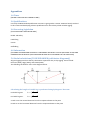
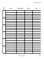
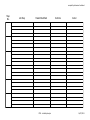
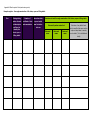
ETNZ Safe Rigging Practices for the Entertainment Industry in New Zealand Version: Draft Andrew Gibson, Steve Sanders, Sam Johnston, and Grant Gilbert 7/1/2013 Scope The aim of this guide is to provide an overview of acceptable entertainment rigging practises for venues throughout New Zealand. There is a number of well written entertainment rigging texts on the market and it is not our intent to create another of these. For the purposes of this document the term venue extends beyond the traditional theatre space and includes: x x x x x Arenas; Ballrooms; Conference rooms; School halls; Any other indoor area that is being used for the purposes of entertainment event. Outdoor structures, staging, and consideration for persons climbing or being suspended from trusses are not considered in this document. We propose to broaden the scope of this document to include these topics in future versions. Administration This guide has been produced for the Entertainment industry of New Zealand through ETNZ. The major contributors are: Andrew Gibson Steve Sanders Sam Johnston Grant Gilbert The primary contact for this guide is: Andrew Gibson 26 Saville Row, Johnsonville, Wellington, 6037 [email protected] This guide has been presented to the industry in July 2013 during the ETNZ conference as a draft for industry feedback. Copies of the draft can be obtained via the ETNZ website (www.etnz.org). Following consideration of the feedback, version one of this guide will be released to coincide with the 2014 annual general meeting for ETNZ. This document is to be reviewed again in 2015 and then reviewed every four years after that. The review committee are to be endorsed by the ETNZ Executive after the release of each version of the guide. Summary [THIS SUMMARY WILL BE INCLUDED INTO A GUIDE FOR SAFE WORKING PRACTICES IN THE NEW ZEALAND THEATRE AND ENTERTAINMENT INDUSTRY] Terms [TO BE COMPILED] Health and Safety Notifiable work Any rigging work that involves the following is considered notifiable: x x Involves lifting over 500 kg over five metres, and/or Involves working where the worker could fall five metres or more. Hazardous work notifications can be completed online at: http://www.osh.govt.nz/tools/HazardousWork/Pages/HazardousWork.aspx Risk Assessment A job risk assessment is the process of identifying the risks associated with a particular type of work and environment, then assessing them on a likelihood of occurrence verses the severity of consequence matrix. Control measures are stated and the corresponding reduction in the matrix score indicated on the assessment. Risk assessments are covered in detail ŝŶ ͞A guide to Safe tŽƌŬŝŶŐWƌĂĐƚŝĐĞƐŝŶƚŚĞEĞǁĞĂůĂŶĚdŚĞĂƚƌĞĂŶĚŶƚĞƌƚĂŝŶŵĞŶƚ/ŶĚƵƐƚƌLJ͟which can be found with the following link: (http://www.etnz.org/files/Guide-‐Version12.pdf) Method Statement (Job Safety Assessment) A Method Statement is a means of documenting the process that will be undertaken to achieve the job. It provides a time line, a hierarchy of responsibility, equipment to be used, and how. A Method Statement is a means of communicating how the risks identified in the Risk Assessment are to be managed for a particular job. There is a Method Statement template in Appendix 7.0 as well as in the resources section on the ETNZ website (www.etnz.org) under the heading Job Safety Assessment. The following six questions can be used to help perform this assessment. If you answer NO to any of the primary questions, the secondary questions can be used as an alternative approach. If you can answer YES to all primary or the relevant secondary questions then proceed with the task. If you answer NO to primary or subsequent secondary questions, ask your supervisor for advice. The task may require supervision by experienced personnel, or if this is not available, further input from specialists. Have you performed this type of task before or is there a documented procedure? Do you have suitable experience to complete this task? Do you have access to suitable advice? Are you experienced with the equipment to be used? ŽLJŽƵŚĂǀĞĂĐĐĞƐƐƚŽŵĂŶƵĨĂĐƚƵƌĞƌ͛ƐŝŶƐƚƌƵĐƚŝŽŶƐĂŶĚƐƉĞĐŝĨŝĐĂƚŝŽŶƐ͍ Is specialist training or advice available? Do you know the maximum point capacity and weight of every load to be rigged? Can the venue and production provide detailed documentation? Do you have access to specialist advice? Have all safety issues and site hazards been identified and addressed? Can additional measures be installed to reduce risks? Can additional equipment be used to manage risks? Do you have suitable access, including necessary personal protection, to all work areas? Is suitable access equipment available? Are you suitably experienced and qualified in advanced access methods? Do you have clear communication channels to other workers in the area? Are radios or mobile phones available? Do you have a system of hand signals everyone can understand? If you can answer YES to all primary questions, PROCEED WITH THE TASK. If you answered NO to any primary question then YES to a secondary question, check with your immediate supervisor. You may be able to PROCEED WITH CAUTION. Operation may need to include experienced supervisory personnel If you answered NO to any primary question and subsequent secondary questions then STOP. Further specialist input is required. Adapted from North Sea Lifting 2001, The International Working at Height Handbook, North Sea Lifting, Aberdeen Equipment Truss Aluminium (and to a lesser extent, steel) truss is standard product used for suspending lighting, audio visual and scenic equipment in the events industry. There are numerous shapes and sizes of truss available to meet the job requirements. When selecting truss take into account the following considerations: x x x x x Know the potential loads and distribution of loads along the truss; Know the span lengths (distance between support points) you require; Truss must have a label stating: o Manufacturer; o Type of truss; o Serial/batch number; The supplier of the truss must be able to provide: o The materials used to manufacture the truss; o The dimensions and engineering properties of the truss; o The standards the truss was manufactured to (eg EN 13814); o Discard criteria for the truss; o (Ideally) a load table that has some standard spans and standard load configurations1; When renting truss the supplier must be able to present a maintenance policy and service log for the equipment. Lifting Devices The electric chain hoist is another staple piece of equipment in the entertainment industry. Other equipment commonly used for lifting including manual chain blocks, and wire rope winches (often mounted to stands). Like truss, there are a range of sizes, configurations, and manufactures of chain hoists and the type required depends on the proposed use. The following considerations need to be taken: x x x x What loads are to be lifted; What speed do the loads need to be lifted at (it is important to consider the dynamic loads imposed on the supporting structure; How many points is the structure is to be lifted by and the load distribution through these points; The following information must be stated on the lifting equipment: o Manufacturer; o Type of hoist, WLL; 1 As there is an infinite number of load configurations it would be impossible to tabulate them all, however, a structural engineer would be able to calculate the suitability of design based on the dimensional and engineering properties supplied. o o x x x x x Serial number; and If applicable, electrical requirements (voltage, number of phases required, amperage draw); Electrical equipment needs to have a current PAT test tag; When renting lifting equipment the supplier must be able to present a maintenance policy and service log for the equipment; When using more than one hoist to lift a load (e.g. a truss line suspended on two hoists) the WLL of the hoist must be reduced by a factor of 0.75 to allow for discrepancies such as the truss not being perfectly level(Prolyte Group, 2009); Ground support towers often use a combination of truss and a lifting device. These towers need to have an accompanying engineering report stating the allowable height of the tower, allowable loads that can be suspended, and any bracing required to ensure structural stability; When using ground supported structures the load carrying capacity of the ground needs to be factored into load calculations. Rigging Accessories Rigging accessories are considered to be items that are required to connect the truss to the lifting device and the lifting device to the venue. This includes: x x x x x Steel hardware such as shackles, Masterlinks, and Quicklinks; Steel cable such as slings, stingers, and drifts (tracers); Synthetic slings such as web slings and polyester round (endless) slings (e.g. Spansets); Chain slings and clutch chains; Lifting brackets and spreader beams. Rigging accessories need to display: x x x Working load limit; Manufacturer; Batch / serial number. As with other rigging devices the supplier must be able to provide documentation as to the standards the equipment complies with and an inspection and discard criteria as well as, in a rental situation, a maintenance and service log. Rope Rigging As ropes are used in numerous applications in event rigging it is important to consider the following when selecting the appropriate rope: x x x x The purpose of the rope rigging (e.g. a haul line for points / cable picks, to hang banners, or as part of a working at height system); The loads imposed on the rope; The temperature properties of the rope; And the abrasion resistance properties of the rope. The properties of ropes can be provided by the supplier and further information on appropriate use ĐĂŶďĞĨŽƵŶĚŝŶƚŚĞ͞pproved Code of Practice for Load-‐>ŝĨƚŝŶŐĂŶĚZŝŐŐŝŶŐ͟;D/͕ϮϬϭϮͿ͘ Ropes need to be inspected for damage from temperature, chemicals (including rot), and abrasion prior to use. Inspection and Maintenance All equipment must be visually inspected prior to each use. In addition to this all equipment must be periodically inspected by a competent person and documented. x x x The inspection chart must state the asset number or serial number of the piece of equipment, the date put into service, the condition and outcome, and the name of the inspector; The length of period will be defined by the manufacturer or governing legislation and is adjusted according to amount of use and/or the environmental conditions. In any case the minimum requirement is twelve months. (MBIE, 2012); An example of an inspection chart can be found in Appendix 8.0. Methodology Paperwork Plans Plans are an easy way to communicate key information to relevant parties. In order to achieve this they need to: x x x Be specific to the venue; Be of a suitable scale (i.e. readable); Be accurate. Key measurements should also be stated on a plan and elevations should also be included (especially where venue height could be a limiting factor). Load calculations In order to ensure a rigging system can support a show there needs to be an accurate assessment of the loads imposed in the system. Once the loads of the show have been calculated the resultant loads on the rigging and into the venue can also be calculated. Resultant loads can be greatly increased by minor adjustments to the rigging for example making a bridle shallower or taking an extra wrap on a sling around a truss to gain a slightly higher trim height. Where there is a complex load distribution calculations should be checked by a suitably qualified structural engineer. Most rigging texts have a number of useful formulas for determining resultant loads and some are reproduced in Appendix 5.0 Contractor / Client to supply to the venue x x x x x x x Provide a load plan of the proposed rig in the venue at least ten working days prior to arrival; Provide a method statement as outlined above; Provide a risk assessment for particularly hazardous situations; Provide, if requested, proof that equipment complies with current standards and is serviceable (proof of load test, PAT test, and service record); Inform venue of any late changes (e.g. needing to move points elsewhere); Ensure all points are designed with suitable redundancy so that the failure or one component will not result in catastrophic failure. This can be achieved by the use of a secondary suspension at each point where the secondary point is appropriately installed to handle the transfer of load onto it. (Where a venue stipulates a secondary suspension point (safety) must be provided, it is the responsibility of the Contractor/Client to prove that there is sufficient redundancy in their rigging to omit the safeties and obtain a written exemption from the venue management); Ensure that where it is not possible or practicable to install secondary points, a detailed and job specific risk assessment and method statement must be produced which will stand up to peer review or be approved by an industry based engineer. Venue to supply to the contractor/client x x x x x Publish and make available a service load manual to users and sub-‐contractors upon request; Publish additional requirements that the venue has ʹ e.g. all riggers to have completed a safety at height course; Have stamped or permanently labelled and dated on beams allowable loads and load distribution; Check proposed loads from production companies against venue service load manual (seek additional advice e.g. peer review / engineer); Provide a competent person knowledgeable of both the venue and current rigging practices during all major rigging and de-‐rigging procedures. It is envisaged that ETNZ would work with venues to ensure they provide the information required and could hold a copy of this information. Factors of Safety The factor of safety is the ratio between the designated working load limit (WLL) (or safe working load (SWL)) and the load the equipment is expected to fail at. The following are the minimum factors of safety are extracted from the Approved Code of Practice for Load-‐Lifting Rigging (ACPLLR) (MBIE, 2012); Equipment Flat web and round slings Steel rope Chain and accessories Factor of Safety 6:1 5:1 4:1 x In high risk situations (i.e. when suspended over people) the above safety factors must be doubled. Trusses are treated differently to other rigging accessories and typically the allowable load tables use a factor of safety a lot lower than above. For example, Prolyte use a factor of safety of 1.7 for plastic deformation and 2.5 for failure (Prolyte Group, 2008). This is in line with engineered aluminium structures in the construction industry. Likewise, in high risk situation, the loads within the load tables must be halved to double the safety factor. How the rigging equipment is to be used may affect the WLL of the equipment (MBIE, 2012). Treatment Multiplication factor Straight pull 1.0 Basket hitch 2.0 Choke hitch 0.7 Chains from lifting devices must never be choked or prevented from twisting freely in the hook as the twist could damage the chain and / or lifting device, and cause jamming. References Donovan, H., 2002, Entertainment Rigging: A Practical Guide for Riggers, Designers, and Managers, Rigging Seminars; ETNZ, 2011, A Guide for Safe Working Practices in the New Zealand Theatre and Entertainment Industry, version 12, ETNZ, downloaded from www.etnz.org; Higgs, C., 2008, An Introduction to Rigging in the Entertainment Industry 2nd Edition, Entertainment Technology Press; MBIE (Ministry of Business and Employment), 2012, Approved Code of Practice for Load Lifting, downloaded from: http://www.business.govt.nz/healthandsafetygroup/information-‐guidance/all-‐ guidance-‐items/acop-‐load-‐lifting-‐rigging; PLASA, 2010, PLASA National Rigging Certificate Handbook 2nd edition, Professional Lighting and Sound Association; Prolyte Group, 2008, Black Book: Prolyte Technical matters 2nd edition, Prolyte Group downloaded from www.prolyte.com; Prolyte Group, 2009, Operating, maintenance, and Service Manual Prolyft: PLE ʹ 11/12/13 series Chain Hoist, Prolyte Group downloaded from www.prolyte.com. Appendices 1.0 Truss [DEFINE TRUSS AND KEY ELEMENTS HERE] 2.0 Qualifications Currently the New Zealand qualification structure is going under a review. ETNZ are heavily involved in this review and developing relevant qualifications for the industry which includes rigging. 3.0 Governing legislation [STATE RELEVANT LEGISLATION HERE] Health and Safety Load lifting Cranes Scaffolding 4.0 Information [ADITIONAL INFORMATION SOURCES E.G. ENGINEERS AND WHAT TYPE OF QUESTIONS TO ASK AND INFORMATION TO PROVIDE (LIKE PROPOSED METHOD OF ATTACHMENT TO THE STRUCTURE] 5.0 Useful calculations [TO BE EXPANDED (with better diagrams)] All good rigging texts have the key calculations required for day to day rigging. These include: Donovan (2002), Higgs (2002), and PLASA (2010) The following calculations refer to the diagram below: Calculating the length of a bridle leg is performed ǯǣ For bridle leg one: ܮଵ ൌ ඥܸଵଶ ܪଵଶ For bridle leg two: ܮଶ ൌ ඥܸଶଶ ܪଶଶ V1 and V2 are the vertical distances from the respective beams to the point H1 and H2 are the horizontal distances from the respective beams to the point Calculating Bridle leg tension ௐுమ భ For the first bridle leg: ܶଵ ൌ ሺ ு భ మ ሻାሺమ ுభ ሻ ௐுభ మ For the second bridle leg: ܶଶ ൌ ሺ ு భ మ ሻାሺమ ுభ ሻ Where W is the load to be lifted Calculating the resultant loads from a series of point loads on a truss H1 H2 R1 Span The resultants for a single point load can be calculated as follows: ܴଵ ൌ ܹܪଶ ܴଶ ൌ ܹܪଵ R2 The above formula can be used for each point load and the values for R1 and R2 can be summed to give the total resultants. Resultants from distributed and linearly increasing loads can be obtained by applying the total load as a point load through the centre of gravity of the element. Appendix 6.0 Risk Assessment 6.1 Analysing risk (adapted from resources from www.ETNZ.org) HAZARD ASSESSMENT PROBABILITY CONSEQUENCE 1 2 3 4 5 1 HIGH CRITICAL CRITICAL CRITICAL CRITICAL 2 HIGH HIGH CRITICAL CRITICAL CRITICAL 3 MEDIUM MEDIUM HIGH HIGH CRITICAL 4 LOW LOW MEDIUM HIGH HIGH 5 LOW LOW LOW MEDIUM HIGH CRITICAL HIGH MEDIUM LOW Conduct Hazard Assessment Conduct a formal involving at least 3 team Conduct a joint HA by 2 or more Conduct HA. (HA) members with an authorized sign off. members. Hazard (HES) Evaluation Study Health Risk: Low level medical surveillance. Approved by Manager Review controls. Health Risk: surveillance. Consider medical Health risk: periodic review. No health monitoring required. Review controls. Health Risk: immediate mandatory medical surveillance. Change controls after immediate review. KE^YhE^ʹDĂdžŝŵƵŵZĞĂƐŽŶĂďůĞŽŶƐĞƋƵĞŶĐĞƐ People 5 Fatality / Permanent Disability 4 Lost day injury or illness 3 Restricted duties injury 2 Medical treatment injury 1 First aid injury Plant, Property, Process Environment More than $500K damage and/or Major environmental impact production disruption $100K -‐ $500K damage and/or Significant environmental impact production disruption / license violation $50K -‐ $100K damage and/or On or off site environmental production disruption harm $5K -‐ $50K damage and/or Onsite environmental production disruption degradation or minor offsite Under $5K damage and minimal Minor onsite environmental productivity disruption impact PROBABILITY 1 2 3 4 5 Highly Unlikely Unlikely Possible Likely Highly Likely JSA Assessment -‐ Level of Risk Adventure Southland 810 North Road Invercargill 3 6.2 Blank Risk Assessment Risk Factor Severity Control Measures Likelihood At Risk After Controls Risk Factor Consequences Severity Hazard Likelihood Before Controls compiled by Adventure Southland Appendix 7.0 Date: Dept.: Job Location and details: Job Safety Assessment Approved by: These are mandatory fields and must be filled in on all jobs. Consider hazards and controls for people, plant, process, property and environment. Isolation, Permits Team Members PPE Requirements Plant, Equipment, Tools Tags, Barricades General Considerations ETNZ -‐ Job Safety Analysis 16/07/2013 compiled by Adventure Southland Step No. Job Step Hazard Identified ETNZ -‐ Job Safety Analysis Controls Action 16/07/2013 compiled by Adventure Southland Step No. Job Step Hazard Identified ETNZ -‐ Job Safety Analysis Controls Action 16/07/2013 Appendix 8.0 Blank Inspection Chart (www.busines.govt.nz) Example register - thorough examination of all chains, ropes or lifting tackle Size Distinguishing Number of Date when chain, number of mark certificate of test rope or tackle and description and examination was first taken sufficient to Date and by whom carried out into use identify the lifting tackle Particulars of any defect found which may affect the same working Date and name chain, rope or Particulars of each thorough examination of all chains, ropes or lifting tackle Date and name Date and name load, and steps taken to remedy such a defect. (To be initialled and dated)