1
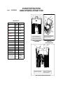
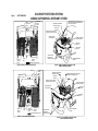
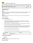
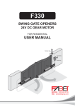
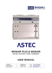
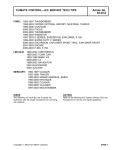
Page 49
OCCUPANT PROTECTION SYSTEMS
AIRBAG SUPPLEMENTAL RESTRAINT SYSTEM
SAFETY/EMISSION
INFORMATION
Ford
urges
careful
consideration
of
the
recommendations that follow. They are based on
analyses of component and vehicle tests, actual
service situations, and engineering judgments.
Disregard of these recommendations may affect the
durability, reliability, handling and performance
characteristics of a completed vehicle and may result
in elevated underbody temperatures, increase the
potential for fire, or may affect the safety of the
occupants in the event of an accident.
AIRBAG
SYSTEM
Subsequent Stage Manufacturers are encouraged
to contact the Ford Truck Body Builder Advisory
Service if they have any questions concerning
these recommendations.
RESTRAINT
Some trucks produced by Ford Motor Company are
equipped with an Airbag Supplemental Restraint
System (SRS). Vehicles equipped with this system
will have the words “AIRBAG” and an air bag symbol
on the VIN plate located on the top driver-side corner
of the instrument panel. System components are
shown in their vehicle locations on the following
pages.
These recommendations are supplemental to U.S.
and Canadian Motor Vehicle Safety compliance
representations provided in the Incomplete Vehicle
Manual (IVM). Also, additional information is provided
in the Ford Truck Service Manual which may be
helpful to subsequent stage manufacturers.
The completed vehicle in the “Loaded” condition must
not exceed the front GAWR, rear GAWR, or the GVWR.
(“Loaded” means the completed vehicle weight with the
maximum fluid capacity necessary for vehicle operation,
plus 150 lb for each designated seating position, and
an additional allowance for any cargo weight
advertised by the manufacturer). The GAWRs and
GVWR are on the label affixed to the cover of the
Incomplete Vehicle Manual.
SUPPLEMENTAL
Included on the vehicle identification number -VINplate (visible through the windshield) of the vehicle,
manufactured by Ford with a driver’s air bag, are the
words “AIR” and “BAG” and a pictogram for the airbag
separating the two (see illustration below).
AIR
BAG
SAMPLE XXXXXXXXXXX
WARNING:
THE SEAT BELT BUCKLE PRETENSIONER,
AIRBAGS AND ELECTRONIC SENSOR MODULE
ARE BAR CODED WITH A UNIQUE SERIAL
NUMBER WHICH IS MATCHED TO THE VEHICLE
VIN. TO MAINTAIN THE OCCUPANT PROTECTION
SYSTEM PERFORMANCE, THE COMPLETED
VEHICLE MUST CONTAIN THE SAME SEAT BELT
BUCKLE PRETENSIONER, AIR BAGS AND
ELECTRONIC SENSOR MODULE THAT WERE
INSTALLED BY FORD MOTOR COMPANY. FAILURE
TO DO SO COULD RESULT IN SERIOUS INJURY IN
THE EVENT OF A COLLISION.
If electrical work is performed in the steering column
area, the instrument panel or the air bag system, the
system must be deactivated to avoid unwanted
inflation of the air bag. To do this, follow the procedure
described on this page.
DEACTIVATION PROCEDURE
1. Disconnect all negative battery cable(s), and
power supplies (if equipped).
2. Wait 1 minute. This is the time required for
backup power supply in diagnostic monitor to
deplete its stored energy.
BB0538
Detailed system and service information will be found
in the Ford Truck Service Manual for the appropriate
type and model year. Ford Motor Company urges the
subsequent stage manufacturers to become familiar
with this system prior to modifying vehicles that are so
equipped.
CAUTION:
DO NOT REMOVE THE STEERING COLUMN,
STEERING WHEEL AND AIRBAG MODULE AS AN
ASSEMBLY FROM THE VEHICLE UNLESS (1) THE
COLUMN IS LOCKED TO PREVENT ROTATION, OR (2)
THE LOWER END OF STEERING SHAFT IS SECURED
(e.g., by wire) IN SUCH A WAY THAT THE STEERING
WHEEL CANNOT BE ROTATED.
WARNING:
TO AVOID ACCIDENTAL DEPLOYMENT AND
POSSIBLE PERSONAL INJURY, THE BACKUP
POWER SUPPLY MUST BE DEPLETED BEFORE
REPAIRING OR REPLACING ANY AIRBAG
SUPPLEMENTAL RESTRAINT SYSTEM (SRS)
COMPONENTS. TO DEPLETE THE BACKUP
POWER SUPPLY ENERGY, DISCONNECT THE
BATTERY GROUND CABLE AND WAIT ONE
MINUTE. BE
SURE
TO DISCONNECT
AUXILIARY
BATTERIES
AND
POWER
SUPPLIES (IF EQUIPPED).
WARNING:
CARRY A LIVE AIRBAG MODULE WITH THE
AIRBAG AND TRIM COVER POINTED AWAY
FROM YOUR BODY. THIS WILL REDUCE THE
RISK OF INJURY IN THE EVENT OF AN
ACCIDENTAL DEPLOYMENT.
WARNING:
DO NOT SET A LIVE AIRBAG MODULE DOWN
WITH THE TRIM COVER FACE DOWN.
3. Remove fasteners retaining driver airbag
module to steering wheel. Disconnect driver
airbag connector and remove the bag from
steering wheel. Place the bag on a flat surface
with trim cover facing upward. Connect an
Airbag Simulator (Part # 105-R0012 in the
Rotunda Tool catalog) to the air bag connector
on the wire harness in the steering wheel.
4. Disconnect passenger airbag module connector
and replace it with an Airbag Simulator (Part #
105-R0012 in the Rotunda Tool catalog) to the
airbag connector on the wire harness in the I/P.
5. Reconnect all negative battery cables and
power supplies (if equipped).
REACTIVATION PROCEDURE
1. Disconnect all negative battery cable(s) and
power supplies (if equipped).
2. Wait 1 minute for backup power supply to
deplete stored energy.
3. Remove Airbag Simulator and reconnect driver
airbag connector. Position driver airbag on
steering wheel and secure with fasteners
(10mm). Tighten fasteners to 2.7-3.7 Nm.[24-32
in-lb].
4. Remove Airbag Simulator
passenger airbag connector.
and
reconnect
5. Reconnect all negative battery cables and
power supplies (if equipped).
6. PROVE-OUT the system.
PROVE-OUT SYSTEM PROCEDURE
Prove-out system means to turn the ignition switch
from OFF to RUN and visually monitor the airbag
indicator. The airbag will light continuously for
approximately six seconds and then turn off. If an
airbag system fault is present, the indicator will
either fail to light, remain lit continuously or light in a
flashing manner. The flashing manner may not
occur until approximately 30 seconds after the
ignition switch has been turned from OFF to RUN.
This is the time required for the diagnostic monitor
to complete the testing of the airbag system. If the
airbag indicator is inoperative and an airbag
system fault exists, a tone will sound in a pattern of
five sets of five beeps. If this occurs, the airbag
indicator will need to be serviced before further
diagnosis can be done.
Page 50
OCCUPANT PROTECTION SYSTEMS
AIRBAG SUPPLEMENTAL RESTRAINT SYSTEM
SAFETY/EMISSION
STEERING
WHEEL
INSTRUMENT
PANEL HARNESS
AIRBAG
AIRBAG
AIRBAG USAGE CHART
VEHICLE
DRIVER
PASSENGER
Windstar
Standard Front
Optional Side
Standard Front
Optional Side
Escape
Standard Front
Optional Side
Standard Front
Optional Side
Explorer
Standard Front Standard Front
Optional Side
Optional Side
Explorer Sport
Standard Front Standard Front
Optional Side
Optional Side
Explorer Sport Trac
Standard Front Standard Front
Optional Side
Optional Side
Ranger
Standard Front
Standard Front
Expedition
Standard Front
Standard Front
Excursion
Standard Front
Standard Front
F150
Standard Front
Standard Front
E-Series Wagon
Standard Front
Standard Front
E-Series Vans
Standard Front
Standard Front
E-Series Cutaway
Standard Front
Standard Front
E-Series Stripped Chassis
Super Duty F-Series Pickups
Super Duty F-Series Pickup
Box Delete and Chassis Cabs
–––
ELECTRONIC
CRASH SENSOR
MODULE
READINESS
INDICATOR
CONNECTOR
AT SAFETY
WALL
CRASH
SENSOR
DO NOT INSTALL ADDITIONAL COMPONENTS IN THE
SHADED AREAS, OR ALTER OR MODIFY THESE AREAS.
FIGURE A - ECONOLINE OCCUPANT
PROTECTION ZONE
72 WAY
CONNECTOR
BATTERY
ENGINE
COMPARTMENT
HARNESS
DO NOT MODIFY OR ALTER ANY COMPONENTS OR AREAS
OF THE VEHICLE IN THE VICINITY OF THE COMPONENTS
THAT ARE IDENTIFIED IN THIS ILLUSTRATION.
FIGURE B - ECONOLINE SUPPLEMENTAL
RESTRAINT SYSTEM
(AIRBAGS, SENSORS AND WIRING)
AIRBAG
DEACTIVATION
SWITCH
PASSENGER
AIRBAG
MODULE
–––
Standard Front
Standard Front
Standard Front
Standard Front
(Includes deactivation
switch except with Crew
Cab models)
DRIVER
AIRBAG
MODULE
DO NOT INSTALL ADDITIONAL COMPONENTS IN THE
SHADED AREAS, OR ALTER OR MODIFY THESE AREAS.
ELECTRONIC CRASH
SENSOR MODULE
DO NOT MODIFY OR ALTER ANY COMPONENTS OR AREAS
OF THE VEHICLE IN THE VICINITY OF THE COMPONENTS
THAT ARE IDENTIFIED IN THIS ILLUSTRATION.
BB0466
FIGURE C - SUPER DUTY F-SERIES OCCUPANT PROTECTION ZONE
Page 51
OCCUPANT PROTECTION SYSTEMS
AIRBAG SUPPLEMENTAL RESTRAINT SYSTEM
SAFETY/EMISSION
PASSENGER
AIRBAG
MODULE
AIRBAG
BATTERY
DEACTIVATION
SWITCH
PASSENGER SUPPLEMENTAL
RESTRAINT (AIRBAG))
PASSENGER AIRBAG DEACTIVATION SWITCH
(MOUNTED ON LOWER CENTER INSTRUMENT
PANEL NEXT TO ASHTRAY)
PROPELLANT
CANISTER
RESTRAINTS CONTROL MODULE
(MOUNTED ON RH A-PILLAR COWL)
INSTRUMENT PANEL
WIRING HARNESS
DRIVER SUPPLEMENTAL
RESTRAINT (AIRBAG)
PROPELLANT
CANSITER
ON OFF
OFF
PASSENGER AIRBAG
CONNECTOR AT
COWL WALL
RESTRAINTS
CONTROL
MODULE
OCCUPANT PROTECTION ZONE
TUNNEL
AREA
DRIVER
AIRBAG
MODULE
AIRBAG SENSORS
(MOUNTED ON
RADIATOR SUPPORT)
FIGURE B - RANGER SUPPLEMENTAL RESTRAINT SYSTEM
(AIRBAGS, SENSORS AND WIRING)
FIGURE A - RANGER OCCUPANT PROTECTION ZONE
PASSENGER
AIRBAG
MODULE
BATTERY
ENGINE COMPARTMENT
HARNESS
PASSENGER SUPPLEMENTAL
RESTRAINT (AIRBAG)
PROPELLANT
CANISTER
PASSENGER AIRBAG DEACTIVATION SWITCH
(MOUNTED ON INSTRUMENT PANEL)
RESTRAINTS CONTROL MODULE
(MOUNTED ON RH SIDE COWL)
L
LOW
FUEL
F
H E
18
C
H
40 5060
30
70
20 00000580
0001010
90
10
0000 100
0
INSTRUMENT PANEL
WIRING HARNESS
3 4
2THEFT
1
5
RPM 10006
CHEW
ENGINE 4x4
0
TUNNEL
AREA
2
3
4
0
5
6
0
PASSENGER AIRBAG
ON OFF
OFF
AIRBAG
DEACTIVATION
SWITCH
CONNECTOR AT
COWL WALL
RESTRAINTS
CONTROL
MODULE
OCCUPANT PROTECTION ZONE
FIGURE C - F-150 OCCUPANT PROTECTION ZONE
BB0454
PROPELLANT
CANISTER
dkb
FM
1
DRIVER
AIRBAG
MODULE
DRIVER SUPPLEMENTAL
RESTRAINT (AIRBAG)
AIRBAG SENSORS
(MOUNTED ON
RADIATOR SUPPORT)
ENGINE COMPARTMENT
HARNESS
FIGURE D - F-150 SUPPLEMENTAL RESTRAINT SYSTEM
(AIRBAGS, SENSORS AND WIRING)