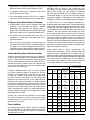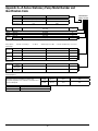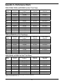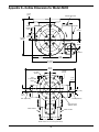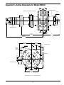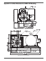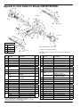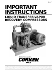
1
ID105J
Installation, Operation
& Maintenance Manual
Z-Series Truck and Stationary Pumps
Model Z2000 Truck Pump
Model Z3200 Truck Pump
Model Z3500 Truck and
Stationary Pump
Model Z4200 Truck Pump
Model Z4500 Stationary Pump
Warning: (1) Periodic inspection and maintenance of Corken products is essential. (2) Inspection, maintenance and installation of Corken products must be made only by experienced, trained and qualified personnel. (3) Maintenance, use and installation of Corken products must comply
with Corken instructions, applicable laws and safety standards (such as NFPA Pamphlet 58 for LP-Gas and ANSI K61.1-1972 for Anhydrous
Ammonia). (4) Transfer of toxic, dangerous, flammable or explosive substances using Corken products is at user’s risk and equipment should
be operated only by qualified personnel according to applicable laws and safety standards.
Warning
Install, use and maintain this equipment according to Corken’s instructions and all applicable federal, state, local laws
and codes. Periodic inspection and maintenance is essential.
Corken One Year Limited Warranty
Corken, Inc. warrants that its products will be free from defects in material and workmanship for a period of 12
months following date of purchase from Corken. Corken products which fail within the warranty period due to defects
in material or workmanship will be repaired or replaced at Corken’s option, when returned, freight prepaid to Corken,
Inc., 3805 N.W. 36th Street, Oklahoma City, Oklahoma 73112.
Parts subject to wear or abuse, such as mechanical seals, blades, piston rings, packing and other parts showing
signs of abuse are not covered by this limited warranty. Also, equipment, parts and accessories not manufactured
by Corken but furnished with Corken products are not covered by this limited warranty and purchaser must look to
the original manufacturer’s warranty, if any. This limited warranty is void if the Corken product has been altered or
repaired without the consent of Corken.
ALL IMPLIED WARRANTIES, INCLUDING ANY IMPLIED WARRANTY OF MERCHANTABILITY OR FITNESS
FOR A PARTICULAR PURPOSE, ARE EXPRESSLY NEGATED TO THE EXTENT PERMITTED BY LAW AND
SHALL IN NO EVENT EXTEND BEYOND THE EXPRESSED WARRANTY PERIOD.
Corken disclaims any liability for consequential damages due to breach of any written or implied warranty on Corken
products. Transfer of toxic, dangerous, flammable or explosive substances using Corken products is at the user’s
risk. Such substances should be handled by experienced, trained personnel in compliance with governmental
and industrial safety standards.
Important notes relating to the European Union (EU) Machinery Directive
Pumps delivered without electric motors are not considered as machines in the EU Machinery Directive. These
pumps will be delivered with a Declaration of Incorporation. The fabricator of the machinery must assure and declare
full compliance with this Directive before the machine in which the pump will be incorporated, or of which it is a part,
is put into service.
Contacting the Factory
Before you contact the factory, note the model number and serial number of your pump. The serial number directs
us to a file containing all information on material specifications and test data applying to your specific pump. When
ordering parts, the Corken service manual or Operations, Installation and Maintenance (IOM) manual should be
consulted for the proper part numbers. ALWAYS INCLUDE THE MODEL NUMBER AND SERIAL NUMBER WHEN
ORDERING PARTS.
The model and serial numbers are shown on the nameplate of the unit. Record this information for future reference.
Model No.
Serial No.
Date Purchased
Date Installed
Purchased From
Installed By
2
Table of Contents
Applicable Notice of ATEX Conformity . . . . . . . . . . . . . . . . . . . . . . . . . . . . . . . . . . . . . . . . . . . . . . . . . . . . . . . . . . . . . . 4
Principles of the Z-Series Coro-Vane® Pump . . . . . . . . . . . . . . . . . . . . . . . . . . . . . . . . . . . . . . . . . . . . . . . . . . . . . . . . . 5
Exclusive Features of Your Z-Series Coro-Vane® Pump . . . . . . . . . . . . . . . . . . . . . . . . . . . . . . . . . . . . . . . . . . . . . . . . 5
Installation of the Z-Series Coro-Vane® Truck Pumps . . . . . . . . . . . . . . . . . . . . . . . . . . . . . . . . . . . . . . . . . . . . . . . . . . 5
Outlet Piping Should Include the Following . . . . . . . . . . . . . . . . . . . . . . . . . . . . . . . . . . . . . . . . . . . . . . . . . . . . . . . . . 6
Bypass System . . . . . . . . . . . . . . . . . . . . . . . . . . . . . . . . . . . . . . . . . . . . . . . . . . . . . . . . . . . . . . . . . . . . . . . . . . . . . . 6
Power Take-off Drive Systems. . . . . . . . . . . . . . . . . . . . . . . . . . . . . . . . . . . . . . . . . . . . . . . . . . . . . . . . . . . . . . . . . . . 6
Hydraulic Drive Systems . . . . . . . . . . . . . . . . . . . . . . . . . . . . . . . . . . . . . . . . . . . . . . . . . . . . . . . . . . . . . . . . . . . . . . . . . 7
Operation of Your Z-Series Coro-Vane® Truck Pump . . . . . . . . . . . . . . . . . . . . . . . . . . . . . . . . . . . . . . . . . . . . . . . . . . 7
How to Transfer From the Truck Tank at Full Capacity . . . . . . . . . . . . . . . . . . . . . . . . . . . . . . . . . . . . . . . . . . . . . . . . . 7
Installation of Your Corken Z-Series Coro-Vane® Stationary Pump . . . . . . . . . . . . . . . . . . . . . . . . . . . . . . . . . . . . . . . 8
The Inlet Piping Should Include the Following . . . . . . . . . . . . . . . . . . . . . . . . . . . . . . . . . . . . . . . . . . . . . . . . . . . . . . . 8
The Outlet Piping Should Include the Following . . . . . . . . . . . . . . . . . . . . . . . . . . . . . . . . . . . . . . . . . . . . . . . . . . . . . 8
The Bypass System Must Include the Following . . . . . . . . . . . . . . . . . . . . . . . . . . . . . . . . . . . . . . . . . . . . . . . . . . . . . 9
A Vapor Equalizing System Should Include the Following . . . . . . . . . . . . . . . . . . . . . . . . . . . . . . . . . . . . . . . . . . . . . 9
Driver Installation . . . . . . . . . . . . . . . . . . . . . . . . . . . . . . . . . . . . . . . . . . . . . . . . . . . . . . . . . . . . . . . . . . . . . . . . . . . . . 9
Operation of Your Z-Series Stationary Coro-Vane ® Pump. . . . . . . . . . . . . . . . . . . . . . . . . . . . . . . . . . . . . . . . . . . . . . . 9
Maintenance of Your Z-Series Coro-Vane® Truck Pump System . . . . . . . . . . . . . . . . . . . . . . . . . . . . . . . . . . . . . . . . 11
Lubrication . . . . . . . . . . . . . . . . . . . . . . . . . . . . . . . . . . . . . . . . . . . . . . . . . . . . . . . . . . . . . . . . . . . . . . . . . . . . . . . . . 11
Pump Maintenance Schedule . . . . . . . . . . . . . . . . . . . . . . . . . . . . . . . . . . . . . . . . . . . . . . . . . . . . . . . . . . . . . . . . . . 11
Preventive Maintenance Program . . . . . . . . . . . . . . . . . . . . . . . . . . . . . . . . . . . . . . . . . . . . . . . . . . . . . . . . . . . . . . . 12
Z-Series Coro-Vane® Seal Replacement Instructions . . . . . . . . . . . . . . . . . . . . . . . . . . . . . . . . . . . . . . . . . . . . . . . . . 13
Repair/Re-build Kits . . . . . . . . . . . . . . . . . . . . . . . . . . . . . . . . . . . . . . . . . . . . . . . . . . . . . . . . . . . . . . . . . . . . . . . . . . . 15
Pump Assembly Instructions For Z-Series Truck Pumps . . . . . . . . . . . . . . . . . . . . . . . . . . . . . . . . . . . . . . . . . . . . . . 16
Appendices
A. Model Number and Identification Code . . . . . . . . . . . . . . . . . . . . . . . . . . . . . . . . . . . . . . . . . . . . . . . . . . . . . . . . 17
B. Features, Benefits, and Operations and Material Specifications . . . . . . . . . . . . . . . . . . . . . . . . . . . . . . . . . . . . . 19
C. Performance Curves and Charts . . . . . . . . . . . . . . . . . . . . . . . . . . . . . . . . . . . . . . . . . . . . . . . . . . . . . . . . . . . . . 20
D. Outline Dimensions . . . . . . . . . . . . . . . . . . . . . . . . . . . . . . . . . . . . . . . . . . . . . . . . . . . . . . . . . . . . . . . . . . . . . . . . 26
E. Parts Details . . . . . . . . . . . . . . . . . . . . . . . . . . . . . . . . . . . . . . . . . . . . . . . . . . . . . . . . . . . . . . . . . . . . . . . . . . . . . 36
F. V-Belt Selection for Stationary Coro-Vane® Pumps . . . . . . . . . . . . . . . . . . . . . . . . . . . . . . . . . . . . . . . . . . . . . . . 41
G. Troubleshooting Guide . . . . . . . . . . . . . . . . . . . . . . . . . . . . . . . . . . . . . . . . . . . . . . . . . . . . . . . . . . . . . . . . . . . . . 42
H. Storage of the Z-Series Coro-Vane® Truck Pumps . . . . . . . . . . . . . . . . . . . . . . . . . . . . . . . . . . . . . . . . . . . . . . . . 44
I. Hydraulic Motor Specifications. . . . . . . . . . . . . . . . . . . . . . . . . . . . . . . . . . . . . . . . . . . . . . . . . . . . . . . . . . . . . . . . 44
3
Applicable Notices for
ATEX 94/9/EC Conformity
Training Instructions:
Coro-Vane® Rotary Vane Pumps
Instructions for the safe application and use of this
product are provided in this manual. Read this manual
completely prior to installation and use of this product.
Only qualified and properly trained personnel should be
allowed to install, operate, and maintain this equipment.
Models Covered:
Mechanical Ignition Sources:
Z/ZH2000, ZX/ZXH2000, Z/ZH3200, Z3500, Z/ZH4200,
and Z4500
This equipment may be direct driven through a coupling by an
electric motor or belt driven by an electric motor. Guards for
the drive mechanism in the assembly intended for personal
protection are to be supplied by the customer. The pump
assembly including the drive system must be grounded to
prevent possible electrostatic discharge. Internal parts of the
pump require fluid (product being pumped) or damage may
occur. Do not run the pump dry (without liquid in the pump).
The application of liquid level controls in the pump system
is recommended. Preventive Maintenance guidelines are
provided in this manual and are to be followed for the proper
operation and performance of the pump.
Product Type:
Intended Application:
The pump models covered by this manual conform to
the European Union ATEX 94/9/EC Directive for explosive
gas atmospheres and transfer of liquefied gases such as
Liquefied Petroleum Gas, anhydrous ammonia, freons,
etc. Electric motors for these pumps in the assembly
must comply with all applicable requirements for local,
federal, and regional codes and regulations.
Possible Misuse Warning:
Sound Levels:
The designated pump models must only be installed
in systems designed for its intended use, similar to the
examples presented in this manual.
When properly installed and operated, these pumps
do not exceed 85 dbA noise levels at a distance of one
meter (3.281 ft) from the surface of the pump. This value
is highly dependent upon the installation and may vary
from installation to installation.
ATEX Classification:
Group II; Category 2; G; Temperature Class T4 – T5
Piping Forces and Moments:
Maximum Allowable Pipe Torque
Z/ZH/ZX/ZXH2000
These products are classified under the ATEX directive
as Equipment – Group II – Category 2 – equipment is
intended for use in areas where explosive atmospheres
caused by gases or vapors (G) may be present. The
surface Temperature Class rating is a range between T4
275°F (135°C) and T5 212°F (100°C).
Inlet
Outlet
Nameplate:
Size
Torque
Size
Torque
2 in. (50 mm)
1,650 in•lbs (186 N•m)
2 in. (50 mm)
1,650 in•lbs (186 N•m)
Z/ZH3200 and Z3500
Inlet
Outlet
Auxiliary
Inlet
Size
Torque
Size
Torque
Size
Torque
3 in. (80 mm)
1,800 in•lbs (203 N•m)
2 in. (50 mm)
1,650 in•lbs (186 N•m)
2 in. (50 mm)
1,650 in•lbs (186 N•m)
Size
Torque
Size
Torque
Size
Torque
4 in. (100 mm)
1,900 in•lbs (215 N•m)
2 in. (50 mm)
1,650 in•lbs (186 N•m)
2 in. (50 mm)
1,650 in•lbs (186 N•m)
Z/ZH4200
Inlet
Outlet
Auxiliary
Inlet
Explosion protection
ATEX directive
94/9/EC marking
Equipment classified
as Group II—Catagory 2
Preventative Maintenance
Pump Maintenance Schedule:
ATEX and File number
machinery
directive
Surface temperature range
T4 275°F (135°C)
T5 212°F (100°C)
Daily
Lubricate bearings
Inspect drive couplings
Clean inlet strainer
Check for leaks
Inspect hose and fittings
Explosion gas atmosphere
High level
4
Monthly
X
3 Months
X
X
X
X
Principles of the Z-Series
Coro-Vane® Pump
Installation of Your Corken
Z-Series Coro-Vane® Truck Pump
The Corken Z-Series truck pump is a special type of rotary
positive displacement pump, known as a sliding vane pump.
Before installing of your pump, remove all temporary
plastic plugs.
The sliding vane pump has many of the positive displacement
advantages of the gear pump, plus the ability to compensate
for wear, and operate at a lower noise level.
The installation of the Z-Series CORO-VANE® pump is
simple. However, in order for the pump to deliver optimum
performance, the principles discussed in this book should be
followed. The piping details are furnished to illustrate methods
proved by hundreds of installations. Your own needs may
require slight variations, but every effort should be made to
follow the recommendations identified in this manual.
The sliding vane pump consists of a rotor turning in a cam
(liner) machined eccentrically in relation to the rotor; thereby
displacing the liquid trapped between the rotor, cam and
vanes. The Corken Z-Series pumps are made with vanes
produced from advanced polymers which exhibit extremely
low coefficients of friction. The vanes are self-adjusting for
wear which gives the pump long life.
For the transfer of flammable liquids like LPG, the pump
must be installed according to the applicable local safety
and health regulations. The installer and/or the user must
take into account the following:
Exclusive Features of Your
Z-Series Coro-Vane® Pump
• Potential risk due to local conditions regarding the
installation and operation (e.g. poor ventilation and
additional risks due to other elements in the vicinity, etc.).
The pumping of volatile liquids is one of the most difficult of all
pumping jobs, and pumping from a delivery truck makes it even
more difficult, so more attention must be given to the design and
manufacture of the pump and to its installation and operation.
• Qualification of the personnel.
• Type of liquid being transferred.
• Specific safety measures to be applied (e.g. gas
detection, automatic shut-off valves, personal protection
equipment, etc.).
In addition to being especially suited for handling volatile
liquids, your Z-Series pump has a number of features to help
make it more easily operated and maintained.
See Appendix A for shipping weight and Appendix D for
outline dimensions.
This model has been registered and listed by the
UNDERWRITERS’ LABORATORIES, INC. for use in the
handling of LP-Gas and Ammonia.
A rotation arrow is located on the side of the pump so check the
PTO to determine its direction of rotation. The Z-Series pump
will match either PTO rotation. Connect the drive shaft to the
pump shaft that turns the pump in the direction of the arrow.
The CASE AND HEADS are made of ductile iron for extra
strength and toughness.
The VANES are manufactured of advanced polymers to
provide excellent life and quiet operation. After long service,
the vanes are simply and inexpensively replaced.
The PTO selection is important. The pump requires a
PTO with an average output speed of 500 to 800 RPM
when the truck engine is operating at the proper speed
to maintain oil pressure and water circulation.
Both the CAM and the SIDEPLATES are easily replaced
should the need arise. Sideplates may be reversed for
extended service life.
The DRIVESHAFT connecting the pump to the PTO should
be of the “splined” or slip type. This type driveshaft permits
the shaft to adjust for PTO movement and twisting of the truck
frame. A fixed driveshaft transfers the forces directly into the
pump and PTO and will shorten the life of both considerably.
The yokes of the driveshaft universal joints must be positioned
as shown. Improper positioning will soon wear them out and
potentially destroy the bearings in the pump and PTO.
The MECHANICAL SEAL is designed for longer life under greater
loads and may be inspected or replaced without disturbing the
piping of the pump. No special tools are needed.
BEARINGS are heavy-duty roller type for long bearing life.
PRESSURE GAUGE connections, 1/4 in. pipe thread, are provided.
INLET PIPING should be as short as possible with
minimum restrictions so that the pressure drop is limited.
Inlet Piping is not generally required on the Z3200 or
Z4200. These pumps are bolted directly to the tank
internal valve and must be installed in accordance with
the valve manufacturer’s instructions.
The RELIEF VALVE is built-in and nonadjustable. The
valve is preset at the factory.
NOTE: EVEN WITH THIS INTERNAL SAFETY VALVE,
AN EXTERNAL BYPASS VALVE MUST BE INSTALLED.
5
Figure 1: Shaft Alignment
The Outlet Piping Should Include the Following:
1. A pressure gauge should be installed in the pump
outlet or near it. A pressure gauge is necessary to
determine the efficiency of your pumping system.
2. A hydrostatic relief valve is required by most state
laws and for your own safety.
Figure 2: Universal Joint Alignment
3. If a meter with a vapor eliminator is installed, pipe the
eliminator outlet to the top of your tank. Never pipe
the eliminator into the pump inlet piping or into the
liquid part of the system at any point.
Power Take-off Drive Systems
Proper pump operation and long life are directly
dependent upon a good drive system. Many truck pumps
utilize a power train consisting of shafts and universal
joints from a power take-off shaft on the truck engine to
the pump.
4. The meter back-pressure valve may be piped into the
tank top or into the pump inlet piping.
There are several basic principles that should be followed
in laying out a PTO drive. These principles should not be
violated. Following them will produce a workable power
train that results in long pump life and reduced drive wear.
5. The discharge piping should be at least the same size
as the meter.
The Bypass System
The internal safety relief valve is intended as a safety
device and not as an operational bypass valve. The
external bypass valve should be set at a differential
pressure lower than the internal relief valve and may be
connected to the tank at any convenient point, liquid or
vapor. All Z-Series pumps (except ZX2000, which is set
at 175 psid) are set near 150 psid.
ZH2000
Foot mounted hydraulic drive with NPT
connections
ZX2000
Foot mounted with NPT connections and high
pressure internal relief valve spring (175 psid
rather than the standard 150 psid)
First, the driver shaft and the driven shaft must be parallel
to one another within plus or minus one degree. Improper
alignment will cause jerking and back and forth “whip”
to the pump shaft, thereby imparting a surging pulsation
to the liquid flow, which results in noise, vibration and
abnormal wear.
Second, the angle of the “floating” shaft should be within
the limits for the particular equipment being used (usually
a maximum of 15° at pump speeds up to 800 RPM). To
ensure that shaft expansion or contraction does not distort
the drive system, a splined slip joint should be placed
between the two universal joints. The drive shaft should
be of the “splined” or slip type to permit the shaft to adjust
for PTO movement and twisting of the truck frame. A fixed
drive shaft transmits the forces directly to the pump and
PTO which will shorten the life of both considerably.
ZHX2000 Foot mounted hydraulic drive with NPT
connections and high pressure internal relief
valve spring (175 psid rather than the standard
150 psid)
Third, the yokes of the drive shaft universal joints must
be in a parallel position. Figures one and two illustrate the
proper arrangement.
6
Improper installation of the U-joints will soon destroy
them along with the bearings in the pump and PTO.
Properly mounted, the second universal gives uniform
motion to the drive shaft by compensating for the rotational
error introduced by the first U-joint. An even number
of universal joints (two, four, six, etc.) should always be
used. An odd number of U-joints will cause unbalanced
pump shaft rotation. This problem becomes greater with
increased angularity.
data are on the performance charts in Appendix C.
Information on the Char-Lynn hydraulic motor is found in
Appendix I.
Other points to consider include the proper sizing of the
shaft components with a maximum horsepower load to be
expected, good alignment of hanger bearings and proper
pump coupling alignment. Improper PTO systems count for
a high percentage of truck pump failures. Always remember
to disengage the clutch before shifting the PTO into gear.
Shifting the PTO into gear without disengaging the clutch
imparts an enormous shock on the PTO, drive shaft, pump
and meter and will soon damage one or all of them.
The following steps should be performed for the initial
pumping operation:
Operation of Your Z-Series
Coro-Vane® Truck Pump
Performance curves and charts are provided in Appendix C.
1. Close the shutoff valve on the end of the delivery hose.
2. Follow the instructions of the internal valve
manufacturer for putting the valve into operation.
3. Start the pump and circulate liquid through the
external bypass system.
For proper installation of pump drives, follow the rules
listed below:
4. If your system has a Corken T-166 bypass valve, adjust
the valve by turning the adjusting screw counter clockwise
until the pump discharge pressure gauge shows nearly
the same pressure it did before you started the pump.
Turn the adjusting screw clockwise until the gauge
indicates about 100 to 115 psid above the tank pressure.
If a bypass valve of another make is used, follow the
instructions provided for adjusting the valve.
1. Driver shaft and pump shaft must be parallel, plus or
minus one degree.
2. Operating angle of the “floating” shaft must be 15
degrees maximum.
3. Universal yokes must be in line and parallel.
5. You may increase the speed of your pump as long as
it increases the capacity of the pump and does not
exceed the excess flow valve or external bypass valve
setting. The one exception occurs when the pump is
used to “Pump On” or to load the truck tank. In this
case, the pump inlet conditions are poor at best so
the pump should be operated at a slower RPM.
4. Splined slip joints must be used where needed.
5. Use an even number of universal joints.
6. Always use the least practical number of shafts.
PTO selection and drive system design is extremely
important. The PTO should have an average output
speed of 500 to 800 RPM when the truck engine is
operating at the recommended speed.
NOTE: IF PUMP SPEED IS INCREASED, BE
CERTAIN THE METERING SYSTEM WILL
HANDLE THE INCREASED FLOW.
The designer of the drive system must select a PTO drive
shaft capable of meeting the torque requirements of the
pumping system.
WHEN PROPERLY INSTALLED AND OPERATED,
Z-SERIES CORO-VANE® TRUCK PUMPS DO NOT
EXCEED AN 88 dBA NOISE LEVEL AT A DISTANCE
OF ONE METER (3.281 ft) FROM THE SURFACE OF
THE PUMP.
Hydraulic Drive Systems
Truck pumps are also driven by hydraulic systems, consisting of
an adaptor, a motor, a pump, a cooler and connecting hoses.
How to Transfer From the Truck
Tank at Full Capacity
The truck pump’s shaft must be properly aligned with the
hydraulic motor’s shaft to avoid excessive stress on the
truck pump’s main and thrust absorbing bearings. See
Appendix D for outline dimensions.
To move volatile liquids rapidly from a truck tank requires
that a condition be maintained within the truck tank
that keeps the liquid and the vapors above the liquid in
equilibrium—to prevent violent boiling of the liquid. As liquid
is removed from the tank, some of the liquid boils to form
vapor to fill the space created as the liquid leaves. If this
action becomes too violent, the pump will begin to make
noise, and the capacity will be reduced. Truck pumps can
The sizing of the hydraulic motor, the hydraulic pump and
the hydraulic oil cooler must be done using the operational
requirements of the truck pump, i.e., flow rate, differential
pressure, pump speed, required torque and power. These
7
lower the truck tank pressure from 5 psi to 10 psi (below
the starting tank pressure) if there is no means provided
for equalizing—and then the trouble starts! As the weather
gets colder, the worse this condition will become. You can
detect this “pull down” in pressure by observing your truck
tank pressure gauge as the pump is operating.
To prevent this violent liquid boiling, pressure in some form
must be introduced into the truck tank. The simple way
to accomplish this is to “equalize” between the truck tank
and the receiving tank. Equalizing takes the higher pressure
vapors from the receiving tank and returns them to the truck
tank. As a result, the void left by the receding liquid is filled.
This in turn lessens the need for the liquid to boil excessively.
The equalizing principle is necessary for volatile liquids.
Figure 3
(0.6 m) above the pump inlet nozzle, with four feet (1.2
m) considered standard.
• The foundation for the pump is important. The foundation
must be firm, level and preferably made of concrete.
The suggestions in figure three should be observed.
NOTE: EQUALIZING BETWEEN TANKS OR
THE ADDITION OF PRESSURE IS NOT A LEGAL
TRANSFER IN MOST STATES. IF EQUALIZING
LINES ARE NOT PERMITTED REMEMBER THAT A
QUIET PUMP IS AN EFFICIENT PUMP. A NOISY
PUMP IS NOT EFFICIENT AND THE CONDITIONS
THAT CAUSE THE NOISE ALSO CAUSE WEAR TO
INTERNAL PARTS. OPERATE THE PUMP AT SPEEDS
THAT RESULT IN A “QUIET” TRANSFER.
• Potential risk due to local conditions regarding the
installation and operation (e.g. poor ventilation and
additional risks due to other elements in the vicinity, etc.).
• Qualification of the personnel.
• Type of liquid being transferred.
NOTE: EVEN WITH THIS INTERNAL SAFETY VALVE, AN
EXTERNAL BYPASS VALVE MUST BE INSTALLED.
• Specific safety measures to be applied (e.g. gas
detection, automatic shut-off valves, personal protective
equipment, etc.).
Installation of Your Corken Z-Series
Coro-Vane® Stationary Pump
The following table shows the weight of the bare pump
for each model. For handling a bare pump, lifting slings
should be used. Web slings are preferred over metal
slings to minimize damage to the paint. See Appendix D
for outline dimensions.
NOTE: All pumps should be installed in a well
ventilated area.
The installation of the Coro-Vane® pump is simple.
However, in order for the pump to deliver optimum
performance, the principles discussed in this book
should be followed. The piping details are furnished to
illustrate methods proved by hundreds of installations.
Your own needs may require slight variations, but every
effort should be made to follow the recommendations
identified in this manual.
The Inlet Piping Should Include the Following:
1. The tank excess flow valve (EFV) should have a flow
rate of 1-1/2 to 2 times the capacity of he pump. Do
not use an EFV without knowing its flow capacity.
2. The tank shut-off valve must be a free-flow type and
not a standard globe valve.
No pump can discharge more liquid than it receives, so
the pump location and the inlet piping must be given
careful attention. If the inlet piping is inadequate to supply
the demand of the pump, you may expect trouble.
3. A strainer of the “Y” type, with 30 to 40 mesh screen,
must be on the inlet line of the pump. (Mesh size
indicates the number of openings per lineal inch).
4. Use a flexible connection in the pump inlet and outlet
piping to compensate for piping strains.
For the transfer of flammable liquids like LPG, the pump
must be installed according to the applicable local safety
and health regulations. The installer and/or the user must
take into account the following:
5. Use an eccentric swage at the pump inlet nozzle to
change the line size (flat side up).
• The pump must be located as near the storage tank as
possible. The complete inlet line, including the vertical line
from the tank must not exceed 12 feet (3.7 m) in length.
6. Make the inlet line level or slope it downward to the pump.
• The bottom of the tank must be no less than two feet
1. A pressure gauge should be installed in the pump
The Outlet Piping Should Include the Following:
8
outlet or near it. A pressure gauge is necessary to
determine the efficiency of your pumping system.
Improper motor wiring will cause expensive motor
difficulties from low voltage. If you suspect you have
low voltage, call your power company. Connecting your
motor for the voltage you have available is important
too. The motors furnished with the stationary pumps are
usually dual voltage, so you must be sure of the voltage
your power company is supplying you. Your motor will be
completely ruined if it is connected to the wrong voltage.
2. A hydrostatic relief valve is required by most state
laws and for your own safety.
3. If the outlet piping exceeds 50 ft (15.2 m) in length a
check valve should be installed near the pump outlet.
The Bypass System Must Include the Following:
A humid climate can cause problems, particularly in
explosion proof motor applications. The normal breathing
of the motor, and alternating between being warm when
running and cool when stopped, often will cause moist
air to be drawn into the motor housing. This moist air will
condense, and may eventually add enough free water
to the inside of the motor to cause it to fail. To prevent
this, make a practice of running the motor and pump at
least once a week on a bright, dry day for an hour or so
(pumping through the bypass system). In this period the
motor will heat up and vaporize the condensed moisture,
and drive it out of the motor. No motor manufacturer will
guarantee an explosion-proof or totally enclosed motor
against damage from moisture.
1. A pump bypass system must be installed. If the pump
discharge is shut off before the driver is stopped,
dangerously high pressures can develop, unless a
bypass valve is installed to permit the pump to discharge
back to the supply tank, at a predetermined pressure.
2. The pump may have an internal relief valve, but it is
intended as a safety relief valve device and not an
operational bypass.
3. Always install an external bypass relief valve (such as
the Corken ZV200 or B177) in the pump discharge line.
The bypass valve may discharge into the tank at any
convenient opening, either liquid or vapor; however, it
should not connect into the pump inlet piping system.
Engine drivers pose a special consideration. The
manufacturer’s instructions must be followed. When the
stationary pump is equipped with an engine from the
factory, the engine speed should normally not exceed 1,800
RPM. Excessive engine speed will overload the engine and
cause early failure. The engine loses 3% of its power for
every 1,000 ft (305 m) above sea level, so if your installation
is at a higher altitude than normal, consult the factory.
A Vapor Equalizing System Should be Included:
To obtain maximum performance from your Coro-Vane®
pump, a vapor equalizing system should be installed. This
system is simply a pipe connecting the vapor sections of
the tank being unloaded and the tank being filled. This
equalizing line allows vapor to move freely between the
two tanks (in either direction) and assures that both tanks
remain at the same pressure.
Motor
Recommended
wire size, AWG1
Approximate
Length of run (ft)
full load
0–100
to 200 to 300
amperes
3
1
115
34.0
6
4
2
220
17.0
12
8
8
3
230
9.6
12
12
12
460
4.8
12
12
12
5
1
115
56.0
4
1
1/0
230
28.0
10
6
4
3
230
15.2
12
12
10
460
7.6
12
12
12
7-1/2
1
230
40.0
8
6
4
3
230
22.0
10
10
8
450
11.0
12
12
12
10
3
230
28.0
8
8
8
460
14.0
12
12
12
15
3
230
42.0
6
6
6
460
21.0
10
10
10
20
3
230
54.0
4
4
4
460
27.0
8
8
8
25
3
230
68.0
2
2
2
460
34.0
6
6
6
30
3
230
80.0
1
1
1
460
40.0
6
6
6
40
3
230
100.0
2/0
2/0
2/0
460
52.0
4
4
4
50
3
230
130.0
3/0
3/0
3/0
460
65.0
2
2
2
1 Based upon 3% voltage loss copper wire type TW. Single phase
motor calculations are based on two times distance.
As liquid is withdrawn from a tank, it must be replaced
by an equal amount of vapor or the pressure in the tank
will drop. If an equalizing line is not present, this vapor
is formed by “boiling” of the liquid and a reduction of
the tank’s pressure. Meanwhile, the tank being filled
experiences a pressure increase as the rising fluid levels
compresses the vapor space above it. A vapor equalizing
line will eliminate both of these problems and will reduce
pumping time, differential pressure, noise and wear on
the entire system. Slow transfer rates will minimize these
effects, and reduce the need for a vapor equalizing line.
However, today’s high transfer rates require that a vapor
equalizing line be installed.
Hp
Another way to consider this principle is to remember
that it takes two holes in an oil can for oil to be poured
smoothly from the can; one for the oil to exit and the
other for the air to enter.
Driver Installation
The wiring of your electric motor is extremely important
and must be done by a competent electrical contractor.
The following wire sizing chart indicates the minimum
standards for wire sizes.
9
Motor
phase
Volts
Operation of Your Z-Series
Stationary Coro-Vane® Pump
8. Open any shut-off valves between the bypass valve
and the storage tank.
9. Make a note of all pressure gauge readings, especially
the pressure gauge located at the discharge of the
pump. Start the pump and circulate the liquid through
the bypass system back to the storage tank.
Performance curves and charts are provided in Appendix C.
The following steps should be performed for the initial
pumping operation:
10. Verify the proper pump rotation direction. There is an
arrow cast in the pump case.
1. Verify the strainer screen is clean.
2. Rotate the pump by hand.
11. An ammeter may be used by adjusting the bypass valve
until the ammeter indicates the full load motor amperage
rating shown on the motor nameplate or maximum
rated differential, whichever comes first. Permit the
pump to circulate liquid for half an hour or more. If the
motor overload protection device stops the motor in this
period the bypass valve setting is too high and should be
readjusted until the motor will run for half an hour. After a
satisfactory setting is achieved, “seal” the valve adjusting
stem to prevent tampering with the adjustment. See
Important Instructions (IH102) and Installation, Operation
and Maintenance (IOM) Manual (IH106) for more details
on the use of the Corken bypass valves.
3. Check V-belt drive or direct drive coupling alignment.
Misalignment will cause accelerated wear of the drive
system, motor bearings and pump.
4. Check motor for proper wiring.
5. Review complete system to make certain the function
of every valve and piece of equipment is clearly
understood. Everyone operating this system must be
properly trained in normal operating procedures and
emergency procedures in event of a malfunction.
6. Close all hose valves.
12. Your pump has an internal relief valve, it must be set
higher than the external bypass setting. The internal
relief valve is factory preset.
7. Slowly open the storage tank bottom shut-off valve
(suction line to the pump). Immediately check the
system for leaks.
13. After initial operation, re-check the strainer screen.
10
Maintenance of Your Z-Series
Coro-Vane® Pump System
Normal wear parts are the mechanical shaft seals, bearings,
vanes and sideplates. All of these parts, plus O-rings and
grease seals, are offered in the Corken “repair kit” listed in
this manual directly after the Seal Replacement Instruction
on page nine. Use only genuine Corken replacement parts
when repairing your Corken Z-Series pump. Follow the
instructions provided with the parts.
All repairs to the pump must be performed by
qualified personnel in a safe manner, utilizing tools
and/or equipment that are free of hazards, and
follows the applicable safety codes of practice set
by the local authorities having jurisdiction. Make
sure the system pressure has been relieved before
attempting any repair to the pump.
When it becomes necessary to repair your pump or
remove it from the system, you must be absolutely
certain that all propane, anhydrous ammonia or whatever
product being pumped is bled from the pump and
connecting piping. Once all the product has safely been
bled from the pump and connecting piping, make certain
no pressure is left in the system. SPECIAL CARE MUST
BE TAKEN DURING THE BLEED DOWN PROCESS TO
AVOID DANGER TO PERSONNEL AND PROPERTY
IN THE AREA. Bleeding a system too fast is a common
mistake and may result in “refrigerated” liquid being left
in the pump and piping even though the pressure gauge
shows no pressure. As the “refrigerated” liquid begins
to warm, more gas will escape causing a dangerous
condition. Take your time in bleeding your system and
make proper provisions to vent or capture the gas in
accordance with local regulations.
Your Corken Z-Series Pump requires regular maintenance
and care like all mechanical equipment. A neglected
or improperly repaired pump will result in premature
failure and cause unsafe conditions. To promote product
longevity and safety, maintenance must be performed
by properly trained technicians. Make sure all safety
systems are in place and the system pressure has been
relieved before attempting ANY maintenance.
Make sure the transfer hoses are not “kinked” which can
cause excessive pump discharge pressure. Always make
sure your hoses are not out of date.
Lubrication
NOTE: ONLY A PROPERLY TRAINED
INDIVIDUAL SHOULD BE ALLOWED TO BLEED
A PUMPING SYSTEM.
There are two lubrication points in which to grease
the pump bearings; one zerk per bearing cap located
at opposite ends of the pump. Four grease relief and
seal ventilation fittings have been provided, two at
each end of the pump, to prevent overgreasing the
bearings. Overgreasing can cause seal failure if grease
passageways are blocked in some way. Clean each
fitting before lubricating the bearings. This practice helps
to prevent foreign material contamination of the bearings
and accidental over-pressurization of the mechanical
seals. Use only ball bearing grease (MIL-G-10924C) with
a temperature rating of -65°F.
Pump Maintenance Schedule
Daily
Lubricate bearings
Monthly
Inspect drive coupling
X
Clean inlet strainer
11
3 Months
X
X
Check for leaks
X
Inspect hose and fittings
X
Preventative Maintenance Program for Z-Series LPG Pumps
5. Lubricate Motor Bearing:
Purpose
By following an effective preventive maintenance
program, unscheduled downtime can be eliminated. This
program should be used by the Operation Manager to
get a maximum utilization of manpower and equipment
as well as to prevent possible unsafe situations and/or
production delays due to equipment breakdown.
Follow the recommendations of the electric motor
manufacturer for the type of grease to use and the
lubrication frequency.
6. Performance Test:
a. While transferring liquid with the pump, check the
pressure at the pump’s inlet port. The pressure
drop in the inlet piping should not be greater than
3 psi.
Scope
The Preventive Maintenance chart in figure four, page 11,
includes the items to be regularly checked and inspected
with a recommended time schedule. These are basic
maintenance recommendations, and each company
should develop their own comprehensive preventive
maintenance program schedule, tailor-made to their
individual operational procedures and requirements.
b. While transferring liquid with the pump, close the
discharge valve(s) so the full flow will be directed
back to the storage tank through the bypass
valve. Then slowly close the valve downstream of
the bypass valves. The discharge pressure of the
pump should increase to the maximum differential
pressure of the pump at no flow conditions (see
Appendix C: Performance Curves).
Maintenance must only be performed by a properly
trained and qualified individual that follows all the
applicable safety procedures.
c. If the maximum differential pressure is not obtained,
the pump must be serviced. See Appendix G
Troubleshooting Guide for additional help.
Procedures
Every procedure herein recommended must be performed
in a safe manner (utilizing tools and/or equipment which
are free of hazards) and following the safety codes of
practice set by the authorities having jurisdiction. These
are general guidelines and are not intended to cover all
the safety aspects that must be considered and followed
while performing these procedures.
d. Replace vanes or sideplates if worn.
7. Tighten all holdown bolts.
8. Inspect motor starter contact points.
1. Visual Inspection:
This must be performed by an authorized and
qualified electrician, based on the electric motors
manufacturer’s guidelines.
This includes checking for leaks, corroded areas,
condition of hoses, piping and fittings, and any
unsafe condition which may hinder the safety of the
personnel and/or the facility.
2. Clean Inlet Strainer Screen:
A clogged strainer screen will create too much flow
restriction and vapor will be formed causing the pump
to cavitate. This reduces the pump’s capacity and
accelerates the wear of the internal parts.
3. Inspect Drive Coupling and Driveline:
Check the coupling alignment and the condition of the
union for cuts, broken sections and wear.
4. Lubricate Pump Bearings:
Use only ball bearing grease, applied with a manual
lubrication pump or gun. Always clean the grease
openings thoroughly before greasing.
12
Z-Series Coro-Vane® Seal Replacement Instructions
Cleanliness
Please Note: The photos listed below contain a Z2000;
however, all Z-Series pumps use the same procedures
for seal replacement.
Even the smallest amount of dirt on your new seal can
cause early failure. Keep all parts, tools and your hands
clean while installing the seal. Never touch the smooth
lapped faces of the carbon rotor or seal seat. For LP-Gas,
anhydrous ammonia and similar liquids, you are trying to
seal a fluid that is 5 to 10 times thinner than water! Your new
seal needs every chance it can get, so keep it clean.
To determine the parts needed for repair, refer to
Appendix A—Model Number and Identification Code,
and Appendix E—Parts Details.
CAUTION! BLEED ALL PRESSURE FROM THE
PUMP AND PIPING BEFORE STARTING TO
INSTALL YOUR SEAL ASSEMBLY.
Workmanship
Your Corken pump is a precision piece of equipment with
very close clearances. Treat it as such. Never use force
during assembly or disassembly (see steps 1 through 10).
Step 1
Step 3
Depressurize and open the pump
Seal seat and grease seal installation
Loosen the head bolts and remove one head with the
bearing cap attached, while holding in on the shaft.
NOTE: The above photo is of a cutaway for better details.
Turn the head over and install the new grease seal face down
by pressing into the bore behind the main bearing. This can
best be accomplished using the old seal seat with the O-ring
removed. Apply a generous amount of light oil to the new seal
seat. Using the protective disc, gently press seal into place.
Step 2
Seal seat and grease seal removal
Step 4
Seal retainer and carbon removal
NOTE: The above photo is of a cutaway for better
details. Remove the head O-ring and place head on the
workbench as shown. Lightly tap the seal out of the head
with a long screwdriver by reaching through the bearing
cap opening. Inspect the inner lip seal and remove, if
necessary, using same process.
Remove the old seal assembly from the pump shaft
while pressing against the sideplate. This will allow the
seal retainer assembly to be removed without pulling the
rotor-shaft out of the pump.
13
Z-Series Coro-Vane® Seal Replacement Instructions
Step 5
Step 7
Seal retainer and carbon installation
Completing installation
Clean the pump and apply a generous amount of light oil.
Install the new seal assembly by aligning the seal retainer
slot with the seal drive pin on the shaft.
Torque the head bolts in a crossing pattern. There is
no need to disassemble or re-shim the bearing caps.
Repeat all of the above steps when replacing the seal
assembly on the opposite side.
Step 6
Step 8
Mechanical seal installation
Lubrication & re-pressurizing
Note: Both sides of the pump are identical; duplicate
procedure to change the seal on the opposite side.
Lubrication
Regrease the bearing after thoroughly cleaning the
grease opening and fittings. If dirt is forced into the
bearings, early failure will result.
Special relief fittings have been provided to help prevent
over-greasing the bearings. Excessive grease may drip
out after lubrication. Over-greasing can damage the
pump bearings and cause seal leaks.
Use only a recommended ball bearing grease. If you use
a hand grease gun, put the grease in slowly and stop as
soon as the relief fitting opens.
Install the new case O-ring onto the head.
Apply a generous amount of light oil to each seal face and
carefully install the head assembly over the pump shaft.
Grease the U-joints and the spline of the drive shaft when
greasing the pump.
Re-pressurize
NOTE: FOR BEST RESULTS, SLOWLY
PRESSURIZE WITH VAPOR PRESSURE.
Please note: If you pressurize with liquid, it will sometimes
refrigerate even though it enters the pump slowly. As a
result, the seal elastomers will not seal properly thereby
causing them to leak.
14
Repair/Re-build Kits
Z4200, ZH4200, Z4500 Repair Kit 3197-X1
Z2000, ZH2000, ZX2000, ZXH2000 Repair Kit 3193-X1
2-224A
O-ring, Buna-N
1
2-231A
O-ring, Buna-N
1
2-231A
O-ring, Buna-N
2
2-234A
O-ring, Buna-N
2
2754-X
Roller bearing
2
4460-X
Roller bearing
2
4262-X
Vane driver
3
4449-X
Vane driver
5
4428
Vane
6
4448
Vane
6
4431-XA2
Seal assembly
2
4464-XA2
Seal assembly
2
4432
Thrust bearing
2
4453
Thrust bearing
2
4435
Thrust bearing mounting ring
2
4454
Thrust bearing mounting ring
2
4439
Bearing cap shim (0.002)
8
4458
Bearing cap shim (0.002)
8
4439-1
Bearing cap shim (0.010)
2
4458-1
Bearing cap shim (0.010)
2
4439-2
Bearing cap shim (0.020)
2
4458-2
Bearing cap shim (0.020)
2
4441
Grease seal
2
4463
Grease seal
2
2270
Shaft key
1
4459
Shaft key
1
Z3200, ZH3200 Repair Kit 3195-X1
2-224A
O-ring, Buna-N
1
2-234A
O-ring, Buna-N
2
2754-X
Roller bearing
2
4262-X
Vane driver
3
4232
Vane
6
4431-XA2
Seal assembly
2
4432
Thrust bearing
2
4435
Thrust bearing mounting ring
2
4439
Bearing cap shim (0.002)
8
4439-1
Bearing cap shim (0.010)
2
4414
Cam
1
4439-2
Bearing cap shim (0.020)
2
4427
Sideplate
2
4441
Grease seal
2
2270
Shaft key
1
Z2000, ZH2000, ZX2000, ZXH2000 Re-Build Kit 3194-X1
Includes all items in the Repair Kit plus the following:
Z3200, ZH3200 Re-Build Kit 3196-X1
Includes all items in the Repair Kit plus the following:
Z3500 Repair Kit 3195-X2
2-228A
O-ring, Buna-N
2
4242
Cam
1
4231
Sideplate
2
2754-X
Roller bearing
2
5554-X
Vane driver
3
3936
Vane
6
4431-XA2
Seal assembly
2
5539
Cam
1
4432
Thrust bearing
2
3935
Sideplate
2
4435
Thrust bearing mounting ring
2
4439
Bearing cap shim (0.002)
8
4439-1
Bearing cap shim (0.010)
2
4439-2
Bearing cap shim (0.020)
2
4443
Cam
1
4441
Grease seal
2
4446
Sideplate
2
2270
Shaft key
1
2270
Shaft key
1
Z3500 Re-Build Kit 3196-X2
Includes all items in the Repair Kit plus the following:
Z4200, ZH4200, Z4500 Re-Build Kit 3198-X1
Includes all items in the Repair Kit plus the following:
All repair and re-build kits have Buna-N O-rings which are suitable for
both LPG and NH3 applications.
15
Pump Assembly Instructions For Z-Series Truck Pumps
1. Place the pump head on a clean work surface with the
bolting flange down.
14. Carefully install the head over the pump shaft and seal
assembly and torque the bolts in accordance with the
appropriate bolt torque pattern drawing. This pattern
ensures even bolting of the head into the case without
deforming the cam inlet port. This is done by bolting
those bolts over the solid portion of the cam port.
2. Press the inner grease seal in through the main
bearing cavity until flush with the bottom of the bore.
Seal lips must be oriented down as shown in each
parts detail drawing.
15. Turn the pump over and remove the first head.
3. Press the main bearing into the head and install the
retainer ring.
16. Install the seal retainer assembly and carbon as
outlined in step 13 above.
4. Install the relief fitting into 1/8 in. NPT threaded hole
and turn the head over.
17. Bolt head to case as described in step 14 above.
Ensure the rotor shaft turns freely in either direction.
5. After lubricating the mechanical seal seat with light oil,
press the seal seat into the head using your fingers.
Make sure the seal seat is fully seated and the shiny
side faces up. Apply a generous amount of light oil
to the seal seat to remove any remaining debris and
fingerprints. Install the case O-ring around the pilot
OD of the head.
18. Slide the bearing race mounting ring onto one end
of the shaft until contact with the main bearing
inner race. Mount the thrust bearing assembly
onto the bearing race mounting ring and install the
bearing cap.
19. Lightly tighten the bearing cap with two opposed bolts
until the rotor shaft cannot be freely turned. Measure
the gap between the head and bearing cap at four
points around the bearing cap. Adjustment may be
necessary to contain the gap within .001 inch. Round
up the average measurement to the nearest even
number. This is the measured amount of bearing cap
shims. Refer to parts pages for shim measurements.
6. Press the outer grease seals into each of the
bearing caps.
7. Press the spring pins into each of the cam key holes.
8. Install the cam key into the pump case. Slide the cam
into the pump case aligning the long inlet slots to the
inlet portion of the case.
9. Install one sideplate and bolt one head into place with
two bolts.
20. Remove the two bearing cap bolts and install the
measured amount of shims plus .006 inch. Install the
four bearing cap bolts and torque in a crossing pattern.
10. Turn the pump onto the assembled head. Ensure
there is enough room to allow the shaft to extend
through the assembled head by six inches.
21. Install the remaining bearing race mounting ring
and thrust bearing assembly on the opposite side
of the pump.
11. While holding the rotor-shaft vertical, install the vane
drivers. Vertically install the rotor-shaft into the unit.
Slide the vanes into each rotor slot ensuring the
rounded tip contacts the cam and the vane slots face
into the direction of rotation as shown in each parts
detail drawing.
22. Perform step 19 again on the opposite side and install
the measured shims plus .002 inch. Install the four
bearing cap bolts and torque in a crossing pattern.
23. Install the shaft key and ensure shaft rotates smoothly.
12. Install the remaining sideplate.
13. Lubricate the pump shaft and seal carbon with light
oil. Install the seal retainer assembly by aligning the
retainer slot onto the seal alignment pin. Carefully
press the seal carbon into the retainer assembly with
the polished face oriented outward by aligning the
carbon notches to the retainer pins. Again, apply a
generous amount of light oil to remove any remaining
debris and fingerprints.
16
Appendix A—Z-Series Truck Pumps Model Number and Identification Code
Base Model
Inlet
Outlet
Auxiliary Inlet
Internal Relief
Weight Bare
Pump lb (kg)
1
Z2000/ZH2000
2" NPT
2" NPT
None
150 psi
100
(45)
ZX2000/ZXH2000
2" NPT
2" NPT
None
175 psi
100
(45)
Z/ZH3200
3" ANSI
2" ell
2" NPT
150 psi
140
(64)
Z/ZH4200
4" ANSI
Dual 2" NPT
2" NPT
150 psi
275
(125)
Model Number
Base X X X X X X
Vane
Type
6 Vanes with
Vane Drivers
Standard
H
Vanes
GCB-50
Standard
G
O-ring
Material
Buna-N
Neoprene ®1
Standard
No charge option
A
B
Neoprene® is a registered trademark of the DuPont company.
Flange Options
WF=Slip-on weld flange
ell = Elbow
All ANSI flanges are 300#
• indicates available flange connections
Inlet Flange
2" NPT
3" ANSI
4" ANSI
•
2" WF
•
•
2" NPT
2" NPT ell
1-1/2" NPT
2" NPT
1-1/2" WF
2" WF
2" weld ell
•
•
Standard
Extra Cost
Options
•
•
•
E
P
S
F
Outlet Flange
Standard
No Cost
Options
Extra Cost
Options
•
•
•
•
•
•
•
•
•
•
•
•
E
G
C
E
D
F
H
Auxiliary Flange
Standard
No Cost
Options
Extra Cost
Options
2" NPT
None
1-1/2" NPT
Blind Flange
1-1/2" WF
2" WF
2" NPT ell
2" weld ell
•
Part Number
Test—Options
3000-X1
Hydrostatic test
•
•
•
•
•
•
17
•
•
•
E
U
C
T
D
F
G
H
Appendix A—Z-Series Stationary Pump Model Number and
Identification Code
Base Model
Inlet
Outlet
Weight—bare
pump lb (kg)
1
Z3500
3" NPT (Standard)
3" NPT Elongated (Standard)
160
(73)
Z4500
4" 300# ANSI
3" 300# ANSI
265
(120)
Model Number
Base X X X X X
Vane
Type
6 Vanes with
Vane Drivers
Standard
H
Vanes
GCB-50
Standard
G
O-ring
Material
Buna-N
Neoprene ®1
Standard
No charge option
A
B
Neoprene® is a registered trademark of the DuPont company.
Flange Options
WF=Slip-on weld flange
ell = Elbow
All ANSI flanges are 300#
• indicates available flange connections
Inlet Flange
Standard
4" ANSI
3" NPT
•
•
S
M
No Cost
Option
4" NPT
•
Q
Extra Cost
Options
3" WF
4" WF
•
•
N
R
Outlet Flange
Standard
Extra Cost
Options
3" ANSI
3" NPT
Elongated
3" WF
Elongated
•
P
•
T
•
V
Mounting Options
Description
Model
Part Number
Maximum Driver (hp)
Ship Weight (mounting only) lb
Mounting set up for V-belt drive. Includes steel
baseplate, adjustable motor slid base, V-belt drive and
enclosed beltguard
Z4500
103-15-
284T
630
Z3500
103-10-
284T
560
Part Number
Test—Options
3000-X1
Hydrostatic test
18
Appendix B—Specifications
Equipment Type & Options
Truck sliding vane pump
Multiple connection options
Optional auxiliary inlet
Applications
Propane bulk transfer
NH3 nurse tanks
LPG cylinders
Auto-fuel pumping
Carousel cylinder filling
Features & Benefits
Sliding vane type:
Positive displacement pump
Heavy duty bearings:
Long bearing life
Single mechanical seal:
Very easy seal replacement and maintenance
Built in relief valve (NPT models only): Factory pre-set—added protection
Pressure gauge connections:
Suction and discharge to reduce piping needs
Reversible side plates:
Longer service life
Operating Specifications
RPM range: 420–800 RPM
Max. working pressure:
Temperature range: -25°F–225°F (-32°C–107°C)
Internal relief valve: Yes
Max. differential pressure: 125 psid (8.6 bar d)
for Z/ZH2000, Z/ZH3200, Z/ZH4200, and Z4500
150 psid (10.3 bar d) for ZX/ZXH2000 and Z3500
400 psig (28.6 bar)
Flow range: 41–400 gpm (155–1,514 L/min)
Material Specifications
Part
Case, head, rotor, reliefvalve cap, bearing cap
Cam
Sideplate
Welding flange
Seal seat
Seal metal parts
Shaft
Vanes and vane drivers
Relief valve spring
Relief valve
Bearing
Thrust bearing
O-rings
Retainer rings
1
Model
Standard Material
All
Ductile iron ASTM A536
All
All
All
All
Z/ZH/ZX/ZXH2000,
Z/ZH3200, Z3500,
Z/ZH4200, Z4500
Gray iron ASTM A48, Class 50
Gray iron ASTM A48, Class 30
Steel
Gray iron
Optional Material
Stainless steel & Ni-Resist
Steel
All
8620 steel
All
Advanced polymers
Z/ZH3200
Steel, cadmium plated
Z/ZH/ZX/ZXH2000, Z3500,
Stainless steel
Z/ZH4200, Z4500
Z/ZH3200, Z3500
Steel
Z/ZH/ZX/ZXH2000,
Stainless steel
Z/ZH4200, Z4500
All
Steel
All
Steel
All
Buna-N
All
Steel
Viton® and Neoprene® are registered trademarks of the DuPont company.
19
PTFE, Viton®, Neoprene®1
Appendix C—Z2000, ZH2000, ZX2000, and ZXH2000
Performance Curves
90
80
750 RPM
Capacity (gpm)1
70
650 RPM
60
600 RPM
50
500 RPM
40
30
25
50
75
100
125
150
Differential Pressure (psid)
1
The chart shows approximate delivery rates as seen in vapor equalized propane systems at 70°F (21°C) with no pressure loss in pump suction piping.
The following will cause increased vaporization of the liquid in the pump suction, adversely affecting the delivery:
1. Restrictions in the suction piping such as internal valves, excess flow valves, elbows, etc.
2. Restriction or lack of a vapor return line
3. Temperatures below 70°F (21°C)
This loss of delivery is not caused by the pump but is a result of the natural thermodynamic properties of liquefied petroleum gases. See the
“GUIDE TO CORKEN LIQUEFIED GAS TRANSFER EQUIPMENT” (CP226) for additional information.
20
Appendix C—Z3200 and ZH3200 Performance Curves
120
750 RPM
110
Capacity (gpm)1
100
650 RPM
90
600 RPM
80
70
500 RPM
60
50
25
50
75
100
125
Differential Pressure (psid)
1
The chart shows approximate delivery rates as seen in vapor equalized propane systems at 70°F (21°C) with no pressure loss in pump suction piping.
The following will cause increased vaporization of the liquid in the pump suction, adversely affecting the delivery:
1. Restrictions in the suction piping such as internal valves, excess flow valves, elbows, etc.
2. Restriction or lack of a vapor return line
3. Temperatures below 70°F (21°C)
This loss of delivery is not caused by the pump but is a result of the natural thermodynamic properties of liquefied petroleum gases. See the
“GUIDE TO CORKEN LIQUEFIED GAS TRANSFER EQUIPMENT” (CP226) for additional information.
21
Appendix C—Z4200 and ZH4200 Performance Curves
400
380
750 RPM
360
340
Capacity (gpm)1
320
650 RPM
300
280
600 RPM
260
240
220
500 RPM
200
180
25
50
75
100
125
Differential Pressure (psid)
1
The chart shows approximate delivery rates as seen in vapor equalized propane systems at 70°F (21°C) with no pressure loss in pump suction piping.
The following will cause increased vaporization of the liquid in the pump suction, adversely affecting the delivery:
1. Restrictions in the suction piping such as internal valves, excess flow valves, elbows, etc.
2. Restriction or lack of a vapor return line
3. Temperatures below 70°F (21°C)
This loss of delivery is not caused by the pump but is a result of the natural thermodynamic properties of liquefied petroleum gases. See the
“GUIDE TO CORKEN LIQUEFIED GAS TRANSFER EQUIPMENT” (CP226) for additional information.
22
Appendix C—Performance Charts
Z2000, ZH2000, ZX2000, and ZXH2000 Coro-Vane® Truck Pumps
Pump
Speed
Differential
Pressure
Approximate Delivery of
Propane1
Brake hp
Required
Pump Torque
Required
RPM
psid (kPa)
gpm (L/min)
bhp (kW)
ft•lb (N•M)
750
50 (345)
82 (309)
2.9 (2.2)
20.4 (27.7)
750
100 (689)
77 (291)
5.8 (4.3)
40.8 (55.3)
750
1502 (1,034)
75 (284)
8.9 (6.63)
62.2 (84.3)
650
50 (345)
69 (261)
2.5 (1.9)
20.4 (27.7)
650
100 (689)
64 (242)
5.1 (3.8)
40.8 (55.3)
150 (1,034)
63 (238)
7.7 (5.7)
62.2 (84.3)
600
50 (345)
63 (238)
2.3 (1.7)
20.4 (27.7)
600
100 (689)
58 (219)
4.6 (3.5)
40.8 (55.3)
600
1502 (1,034)
56 (212)
7.1 (5.3)
62.2 (84.3)
500
50 (345)
52 (197)
1.9 (1.4)
20.4 (27.7)
650
2
500
100 (689)
46 (174)
3.9 (2.9)
40.8 (55.3)
500
1502 (1,034)
44 (166)
5.9 (4.4)
62.2 (84.3)
Z3200 and ZH3200 Coro-Vane® Truck Pumps
Pump
Speed
Differential
Pressure
Approximate Delivery of
Propane1
Brake hp
Required
Pump Torque
Required
RPM
psid (kPa)
gpm (L/min)
bhp (kW)
ft•lb (N•M)
750
50 (345)
112 (424)
6.2 (4.6)
43.4 (58.9)
750
100 (689)
99 (375)
9.9 (7.4)
69.3 (94.0)
650
50 (345)
95 (360)
5.2 (3.9)
42.0 (57.0)
650
100 (689)
84 (318)
8.2 (6.1)
66.3 (89.9)
600
50 (345)
86 (326)
5.0 (3.7)
41.3 (56.0)
600
100 (689)
76 (288)
7.8 (5.9)
64.8 (87.9)
500
50 (345)
70 (265)
3.8 (2.8)
39.9 (54.1)
500
100 (689)
62 (235)
5.8 (4.3)
60.9 (82.6)
Z4200, ZH4200, and Z4500 Coro-Vane® Truck Pumps
1
2
Pump
Speed
Differential
Pressure
Approximate Delivery of
Propane1
Brake hp
Required
Pump Torque
Required
RPM
psid (kPa)
gpm (L/min)
bhp (kW)
ft•lb (N•M)
750
50 (345)
369 (1,397)
12.5 (9.3)
87 (118.0)
750
100 (689)
325 (1,230)
25.1 (18.6)
175 (237.3)
650
50 (345)
316 (1,196)
10.8 (8.0)
87 (118.0)
650
100 (689)
278 (1,052)
21.7 (16.1)
175 (237.3)
600
50 (345)
289 (1,094)
9.9 (7.3)
87 (118.0)
600
100 (689)
254 (961)
20.0 (14.8)
175 (237.3)
500
50 (345)
236 (893)
8.3 (6.2)
87 (118.0)
500
100 (689)
208 (787)
16.7 (12.4)
175 (237.3)
Delivery times are approximate—see note on page 22 for further explanation.
Applies to ZX/ZXH2000 models only.
23
Appendix C—Performance Curves
Z3500
24
Appendix C—Performance Curves
Z4500
25
Appendix D—Outline Dimensions for Model Z2000
16
(40.61)
1/4" x 1-9/16" square key
INTERNAL RELIEF VALVE
SET AT 150 P.S.I.
NOT FOR RECIRCULATING
INSTALLER TO PROVIDE
SEPARATE BY-PASS VALVE
SET AT 125 P.S.I. MAXIMUM
CORKEN, INC.
A Unit Of IDEX Corp.
2-1/8
(5.40)
2-1/8
(5.40)
1-1/8
(2.85)
3-1/4
(8.25)
Outlet:
2" NPT
Internal Relief Valve
1/4" NPT
4-9/16
(11.59)
2-3/8
(6.03)
5-15/16
(15.08)
OUTLET
R K E N
C O
5-1/2
(13.97)
1/4" NPT
R K E N
C O
INLET
3/4
(1.92)
Inlet:
2" NPT
Four 7/16 (1.11)
diameter holes
2-1/2
(6.35)
6-1/2
(16.51)
2-1/2
(6.35)
All dimensions are in inches (centimeters).
26
4-1/2
(11.43)
Appendix D—Outline Dimensions for Model Z3200
10-15/16
(27.78)
1-1/8
(2.86)
4-15/16
(12.47)
17-1/2
(44.43)
8-3/4
(22.23)
3-7/16
(8.73)
1/4"
NPT
2" NPT auxillary inlet
6-3/4
(17.14)
14-15/16
(37.94)
5
(12.70)
INTERNAL RELIEF VALVE
SET AT 150 P.S.I.
NOT FOR RECIRCULATING
INSTALLER TO PROVIDE
SEPARATE BY-PASS VALVE
SET AT 125 P.S.I. MAXIMUM
CORKEN, INC.
A Unit Of IDEX Corp.
1/4" NPT
2" NPT
discharge
Internal
relief
valve
1-5/8 (4.13)
5-11/32
(13.57)
3-7/8
(9.84)
3" 300 lb ANSI flange inlet
6-5/8 BC
(16.83)
8-1/4 D
(20.95)
1/4" square keyway
1-1/8
(2.86)
2-7/16
(6.24)
Eight 7/8" (2.22) diameter holes
All dimensions are in inches (centimeters).
27
Appendix D—Outline Dimensions for Model Z3500
3.25
(8.18)
7.688
(19.5)
1.125
(2.9)
3" NPT
outlet
6.813
(17.3)
6.046
(15.4)
7.188
(18.3)
1/4"
keyway
1.758
(4.5)
3" NPT
inlet
5.500
(14.0)
1.250
(3.2)
1.250
(3.2)
1.750
(4.4)
1.750
(4.4)
3.000
(7.6)
4.125
(10.5)
8.435
(21.4)
7.188
(18.3)
10.738
(47.6)
All dimensions are in inches (centimeters).
28
3.000
(7.6)
4.125
(10.5)
5.375
(13.7)
Appendix D—Outline Dimensions for Model Z4200
1-3/16
(3.01)
Internal relief valve
INLET
1/4" NPT
2" NPT
auxillary
inlet
COR
13-13/16
(35.08)
8
(20.32)
KEN
2-5/8
(6.67)
OUTLET
3-1/4
(8.26)
COR
KEN
1/4" NPT
7-3/4
(19.69)
7
(17.78)
16-31/32
(43.08)
19-1/2
(49.53)
7-7/8 BC
(20.00)
10-1/8 D
(25.72)
Inlet:
4" 300 lb ANSI
flange
2-1/8
(5.40)
1-1/4 (3.18)
1-1/4
(3.17)
5/16" square key
5/16" square key
Eight 7/8 (2.22)
diameter holes
Outlet: 2" NPT
Outlet: 2" NPT
4
(10.16)
4
(10.16)
All dimensions are in inches (centimeters).
29
Appendix D—Outline Dimensions for Model Z4500
8-Ø .875 (2.2)
on a 6-5/8" B.C.
Outlet
3" R.F. 300#
ANSI flange
8.469
(21.5)
Inlet
4" R.F. 300#
ANSI flange
1.875
(4.8)
10.75
(27.3)
5/16"
square key
1.0
(2.5)
6.5
(16.5)
2.875
(7.3)
2.875
(7.3)
8-Ø .875 (2.2)
on a 7-7/8" B.C.
4-5/8 (1.587)
mounting holes
21.121
(53.6)
All dimensions are in inches (centimeters).
30
4.688
(11.9)
4.688
(11.9)
6.125
(15.6)
Appendix D—Outline Dimensions for Model ZH2000
1/4" square keyway
Hydraulic drive adapter assembly
2-1/8
(5.40)
INTERNAL RELIEF VALVE
SET AT 150 P.S.I.
NOT FOR RECIRCULATING
INSTALLER TO PROVIDE
SEPARATE BY-PASS VALVE
SET AT 125 P.S.I. MAXIMUM
CORKEN, INC.
A Unit Of IDEX Corp.
4248
A Division of EATON
6.2 Cubic Inch / Rev
Char-Lynn Hydraulics, Inc.
Model No. 104-1002
Disc Valve Hydraulic Motor
1-1/8 D
(2.85)
Hydraulic motor
3-1/4
(8.25)
10-1/2
(26.63)
13/16
(2.06)
17-11/16
(44.90)
5-15/16
(15.08)
4-9/16
(11.59)
2-3/8
(6.03)
1/4" NPT
Internal
relief
valve
Outlet: 2" NPT
OUTLET
5-1/2
(13.97)
R K E N
C O
1/4" NPT
R K E N
C O
Inlet: 2" NPT
INLET
3/4
(1.92)
2-1/2
(6.35)
2-1/2
(6.35)
6-1/2
(16.51)
All dimensions are in inches (centimeters).
31
4-1/2
(11.43)
8
(20.30)
Appendix D—Outline Dimensions for Model ZH3200
8-3/4 (22.22)
18-1/8 (46.02)
10-15/16 (27.75)
A Division of EATON
6.2 Cubic Inch / Rev
Char-Lynn Hydraulics, Inc.
Model No. 104-1002
Disc Valve Hydraulic Motor
INTERNAL RELIEF VALVE
SET AT 150 P.S.I.
NOT FOR RECIRCULATING
INSTALLER TO PROVIDE
SEPARATE BY-PASS VALVE
SET AT 125 P.S.I. MAXIMUM
CORKEN, INC.
A Unit Of IDEX Corp.
Hydraulic motor
Hydraulic drive
adapter assembly
6-5/8 D B.C.
(16.83)
3-7/8
(9.84)
8-1/4D
(20.96)
2-7/16
(6.24)
1-1/8 (2.86)
1/4" square keyway
Eight 8-7/8 (2.22)
diameter holes
3" 300 lb ANSI flange inlet
10-15/16 (27.78)
1-1/8
4-15/16 (12.47)
(2.87)
3-7/15
(8.73)
1/4" NPT
6-3/4
(17.15)
14-15/16
(37.94)
5
(12.70)
Internal relief valve
1/4" NPT
2" NPT
discharge
5-5/16
(13.57)
All dimensions are in inches (centimeters).
32
1-5/8 (4.13)
Appendix D—Outline Dimensions for Model ZH4200
19-9/16
(49.69)
9-3/4
(24.77)
12-3/8
(31.43)
R
MODEL
SERIAL
NO.
CORO-VANE
CORKEN,INC. A Unit Of IDEX Corp.
POWER OPERATED PUMP FOR LPG OR ANHYDROUS NH
READ CORKEN INSTRUCTION MANUAL BEFORE OPERATING
LISTED 656L
PAT. NOS. 3,072,066 AND 3,392,677
Hydraulic drive
adapter assembly
4
(10.16)
4
(10.16)
7-7/8 B.C.
(20.00)
10-1/8 D
(25.72)
Inlet: 4" 300 lb
ANSI flange
2-1/8
(5.40)
1-1/4 (3.18)
5/16" square keyway
Eight 7/8 (2.22)
diameter holes
Outlet: 2" NPT
Outlet: 2" NPT
1-3/16
(3.01)
Internal relief valve
INLET
2" NPT
auxillary
inlet
1/4" NPT
8
(20.32)
COR
KEN
2-5/8
(6.67)
3-1/4
(8.26)
OUTLET
COR
KEN
A Division of EATON
6.2 Cubic Inch / Rev
Char-Lynn Hydraulics, Inc.
Model No. 104-1002
Disc Valve Hydraulic Motor
Hydraulic motor
OKLAHOMA CITY,OKLAHOMA MADE IN U.S.A.
1/4" NPT
7-3/4 (19.69)
7 (17.78)
16-31/32 (43.08)
All dimensions are in inches (centimeters).
33
13-13/16
(35.08)
Appendix D—Outline Dimensions for Z3500–103 Mounting
All dimensions are in inches (centimeters).
34
Appendix D—Outline Dimensions for Z4500–103 Mounting
All dimensions are in inches (centimeters).
35
Appendix E—Parts Details for Models Z/ZH/ZX/ZXH2000
37 (45 ft•lb)
34
14
36 (25 ft•lb)
Ou
tle
t
36 (25 ft•lb)
35 (15 ft•lb)
14
37 (45 ft•lb)
36 (25 ft•lb)
Inlet
O-ring Code
A
Buna-N
B
Neoprene®1
D Viton
E
Teflon
Ref.
No.
1.
2.
3.
4.
5.
®1
CAUTION: Always relieve pressure in the unit before attempting
any repairs.
Description
4413
4414
4416
4417
1174-3
Case
1
Cam
1
Head
2
Bearing cap
2
Relief valve cap
1
Shim (Z2000, ZH2000)
1
Shim (ZX2000, ZXH2000)
3
Cam key
1
Relief valve
1
Relief valve spring (Z2000,
1
ZH2000)
Relief valve spring (ZX2000,
1
ZXH2000)
Sideplate
2
Vane2
6
Vane driver
3
Rotor—shaft assembly
1
Mechanical seal assembly3
2
Thrust bearing assembly
2
Bearing race mounting ring
2
Grease seal
2
Bearing cap shim (.002) red
As
Bearing cap shim (.010) brown
req.
Bearing cap shim (.020) yellow
4282
7.
8.
4424
4425
4426
9.
1240
18.
See page 15 for repair/re-build kits.
36 (25 ft•lb)
Part No.
6.
10.
11.
12.
13.
14.
15.
16.
17.
Note: Hydraulic motor is not shown.
®1
4427
4428
4262-X
4430-X2R
4431-X_2
4432
4435
4438
4439
4439-1
4439-2
Ref.
No.
19.
20.
21.
22.
23.
Qty
24.
25.
Part No.
Description
2754-X
3253
2760-244
4441
2270
4479-2
4479-2S
2649
Bearing
Cam key pin
Retainer ring
Grease seal
Shaft key—1/4" x 1-9/16"
Flange–2" NPT
Flange–2" welded
Nameplate
Relief valve nameplate
(Z2000, ZH2000)
Relief valve nameplate
(ZX2000, ZXH2000)
Lubrication instruction plate
1/8" NPT relief fitting
1/8" NPT grease zerk
Lubricap
1/4" NPT pipe plug
O-ring—flange 3
O-ring—relief valve cap3
O-ring—case 3
Bolt—hexagon head
Bolt—hexagon head
Bolt—hexagon head
Screw
Lockwasher
4248
26.
4248-1
27.
28.
29.
30.
31.
32.
33.
34.
35.
36.
37.
38.
39.
1
Registered trademarks of the DuPont company.
Slots in vanes must face TOWARDS the direction of rotation.
3 _ denotes O-ring code. See chart above.
2
36
1359
1343
2158
2159
3442
2-231_
2-224_
2-261_
7001-031-NC125A
7001-037-NC150A
7001-043-NC125A
7012-006-SF025E
7206-037A
Qty
2
2
2
2
2
2
1
1
1
2
4
2
2
2
2
1
2
4
16
16
8
8
Appendix E—Parts Details for Models Z/ZH3200
28 (60 ft•lb)
25 (25 ft•lb)
22
12
4
Inlet
4
29 (15 ft•lb)
28 (60 ft•lb)
Outlet
O-ring Code
A
Buna-N
B
Neoprene®1
(25 ft•lb)
Note: Hydraulic motor is not shown.
See page 15 for repair/re-build kits.
D Viton®1
E
CAUTION: Always relieve pressure in the unit before attempting
any repairs.
Teflon®1
Ref.
No.
1.
2.
3.
4.
5.
6.
7.
8.
9.
Part No.
Description
11.
12.
13.
14.
15.
16.
17.
18.
19.
20.
21.
22.
23.
24.
4495-X2R
4242
4232
4231
4488
4239
4417
4438
4435
4439
4439-1
4439-2
2270
4431-X_2
2754
4432
2760-244
1174-2
1359
4441
7012-006SF019E
—
—
2-262_
2-224_
1240
25.
7001-037NC150A
Rotor shaft assembly
Cam
Vane3
Sideplate
Head
Case
Bearing cap
Grease seal
Mounting ring
Bearing shim (.002) red
Bearing shim (.010) brown
Bearing shim (.020) yellow
Shaft key
Mech. seal assembly2
Bearing outer race
Thrust bearing assembly
Retainer ring
Relief valve cap
Lubrication instruction plate
Grease seal
Screw
Not shown
Not shown
O-ring—case2
O-ring—relief valve cap2
Relief valve spring
Bolt—3/8-16 x 1-1/2" hex
head
10.
Ref.
Part No.
No.
26. 2158
27. 1343
Qty
1
1
6
2
2
1
2
2
2
28.
7001-050NC150A
29.
7001-031NC125A
30.
39.
40.
1241
1172-1.5
1172-1.5S
1172-2
1172-2S
1947
4243
4241
3253
3442
4262-X
2-234_
2159
1172-1.5
1172-15S
1172-2
1172-2S
1920-3
4243
2649
4248
1/8" NPT grease zerk
1/8" NPT relief fitting
Bolt—1/2-13 x 1-1/2" hex
head
Bolt—5/16-16 x 1-1/4" hex
head
Relief valve
Outlet flange—1.5" NPT
Outlet flange—1.5" WF
Outlet flange—2" NPT
Outlet flange—2" WF
Outlet flange—1.5" NPT ell
Outlet flange—2" NPT ell
Cam key
Cam key pin
1/4" NPT pipe plug
Vane driver
O-ring—flange2
Lubricap
Aux. inlet flange—1.5" NPT
Aux. inlet flange—1.5" WF
Aux. inlet flange—2" NPT
Aux. inlet flange—2" WF
Aux. inlet flange—blind
Aux. inlet flange—2" NPT ell
Nameplate
Relief valve nameplate
41.
4282
Relief valve shim
42
7206-037A
3/8" lockwasher
31.
As
req.
2
2
2
2
2
1
2
2
8
–
–
2
1
1
32.
33.
34.
35.
36.
37.
38.
16
Description
1
Registered trademarks of the DuPont company.
2
_ denotes O-ring code. See chart above.
3 Slots in vanes must face TOWARDS the direction of rotation
37
Qty
2
4
16
4
1
1
1
1
1
1
1
1
1
1
3
1
2
1
1
1
1
1
1
1
1
As
req.
8
Appendix E—Parts Details for Models Z3500
26
42
16
17
35 (45 ft•lb)
25
24
13
12
11
30
3
32
40
37
15
36
14
5
27
41
38
34 (25 ft•lb)
28
29
23
2
34 (25 ft•lb)
10
44
21
7
20
4
31
39
18
33 (25 ft•lb)
9
8
43
O-ring Code
A
Buna-N
B
Neoprene®1
6
191
34 (25 ft•lb)
22
Note: Hydraulic motor is not shown.
D Viton®1
E
Teflon®1
Ref.
No.
1.
2.
3.
4.
5.
6.
7.
8.
9.
10.
11.
12.
13.
14.
15.
16.
17.
18.
19.
20.
21.
22.
See page 15 for repair/re-build kits.
CAUTION: Always relieve pressure in the unit before attempting any repairs.
Part No.
Description
2-228
2-245
2-259
2-268
1206-3
1206-4
1206-3S
1206-4S
1207-2
1208-1X6R
1224
1309
1343
1359
2158
2159
2270
2649
2754
2760-244
3253
3442
3935
3936
4248
O-ring2
O-ring2
O-ring2
O-ring2
Inlet flange—3" NPT
Inlet flange—4" NPT
Inlet flange—3" WF
Inlet flange—4" WF
Relief valve cap
Rotor shaft assembly
Relief valve
Cam key
Grease relief fitting
Lubrication plate
Grease zerk
Lubricap
Shaft key—1/4"
Nameplate
Outer bearing
Retainer ring
Cam key pin
Pipe plug—1/4" NPT
Sideplate
Vane3
Relief valve warning tag
Ref.
No.
23.
24.
25.
26.
27.
28.
29.
30.
31.
32.
33.
34.
35.
36.
37.
38.
39.
40.
41.
Qty
1
1
1
2
1
1
1
1
1
1
1
1
4
2
2
2
1
1
2
2
2
2
2
6
1
Part No.
Description
Qty
4417
4432
4435
4438
4439
4439-1
4439-2
4441
4431-X2
4985
7001-037NC125A
7001-037NC150A
7001-043NC150A
7012-006SF019E
7012-010SF050E
7206-037A
5534
5537
5539
Bearing cap
Thrust bearing assembly
Thrust bearing mounting ring
Grease seal / Oil seal
Bearing cap shim—0.002"
Bearing cap shim—0.010"
Bearing cap shim—0.020"
Grease seal
Mechanical seal assembly 2
Coro-Vane shaft cover
Hex head bolt
Hex head bolt
Hex head bolt
Screw
Screw
Lock washer—0.375"
Head
Case
Cam
Outlet flange—3" NPT
Elongated
Outlet flange—3" WF
Elongated
Spring
Vane driver
2
2
2
2
2
2
2
2
2
1
24
16
6
9
2
8
2
1
1
5538
42.
5538-3S
43.
44.
1
Registered trademarks of the DuPont company.
_ denotes O-ring code. See chart above.
3
Slots in vanes must face TOWARDS the direction of rotation
2
38
5548
5554-X
1
1
1
6
Appendix E—Parts Details for Models Z/ZH4200
36
GUtMC
36
GUtMC
18
36
GUtMC
37
GUtMC
O-ring Code
A
Buna-N
B
Neoprene®1
D Viton®1
E
Teflon®1
Note: Hydraulic motor is not shown.
36
GUtMC
See page 15 for repair/re-build kits.
CAUTION: Always relieve pressure in the unit before
attempting any repairs.
Ref.
No.
1.
2.
3.
4.
5.
6.
7.
8.
9.
10.
11.
12.
13.
14.
15.
16.
17.
18.
19.
Part No.
Description
4442
4443
4444-X2R
4445
4446
4448
4449-X
4450
4451
4452
4453
4454
4455
4456
4457
4458
4458-1
4458-2
4459
4460-X
2760-283
Case2
1
Cam2
1
Rotor-shaft assembly2
1
Head2
2
Sideplate
2
Vane3
6
Vane driver
5
Relief valve cap
1
Relief valve spring
1
Shim
1
Thrust bearing assembly
2
Bearing race mounting ring
2
Cam key
1
Bearing cap
2
Relief valve
1
Bearing cap shim (.002) red
As
Bearing cap shim (.010) brown
req.
Bearing cap shim (.020) yellow
Shaft key—5/16 x 1-3/4
1
Roller bearing
2
Retainer ring
2
Ref.
No.
20.
21.
22.
23.
Qty
24.
25.
26.
27.
28.
29.
30.
31.
32.
33.
34.
35.
36.
37.
38.
39.
1
Registered trademarks of the DuPont company.
_ denotes O-ring code. See chart above.
3
Slots in vanes must face TOWARDS the direction of rotation
2
39
Part No.
Description
3253
4462
4463
4464-X_2
1172-2
1172-2S
1920-3
4479-2S
4981-2
2649
4248
1359
1343
2158
2159
3442
2-231_
2-234_
2-270_
7001-037NC150A
7001-062NC125A
7012-006SF019E
7206-037A
Cam key pin
Grease seal
Grease seal
Mechanical seal assembly2
Aux. inlet flange—2" NPT
Aux. inlet flange—2" WF
Aux. inlet flange—blind
Discharge flange—2" WF
Discharge flange—2" NPT
Nameplate
Relief valve nameplate
Lubrication instruction plate
1/8 NPT relief fitting
1/8 NPT grease zerk
Lubricap2
1/4 NPT pipe plug
O-ring—discharge flange2
O-ring—auxiliary inlet flange2
O-ring—case2
Bolt—hexagon head
Bolt—hexagon head
Screw
Lockwasher
Qty
5
2
2
2
1
1
1
2
1
1
2
4
2
2
2
2
1
2
24
16
8
8
Appendix E—Parts Details for Model Z4500
O-ring Code
A
Buna-N
B
Neoprene®1
21
D Viton®1
5
Teflon®1
E
18
19
12
11
35
16
4
Note: Hydraulic motor is not shown.
31
20
See page 15 for repair/re-build kits.
CAUTION: Always relieve pressure in
the unit before attempting any repairs.
40
41
29
36
30
39
37
(75 GUtMC
GUtMC
17
25
1
26
38
32
13
28
20
15
32
2
37
14
29
22
9
10
36
34
GUtMC
8
38
6
27
7
3
24
Ref.
No.
1.
2.
3.
4.
5.
6.
7.
8.
9.
10.
11.
12.
13.
14.
15.
16.
17.
18.
Part No.
Description
5522
4443
4444-X2R
4445
4446
4448
4449-X
4450
4451
4452
4453
4454
4455
4456
4457
4458
4458-1
4458-2
4459
4460-X
Case
1
Cam
1
Rotor-shaft assembly
1
Head
2
Sideplate
2
6
Vane3
Vane driver
5
Relief valve cap
1
Relief valve spring
1
Shim
1
Thrust bearing assembly
2
Bearing race mounting ring
2
Cam key
1
Bearing cap
2
Relief valve
1
Bearing cap shim (.002) red
As
Bearing cap shim (.010) brown
req.
Bearing cap shim (.020) yellow
Shaft key—5/16 x 1-3/4
1
Roller bearing
2
Ref.
No.
19.
20.
21.
22.
23.
24.
25.
26.
27.
28.
29.
30.
31.
32.
33.
34.
35.
36.
37.
38.
39.
40.
41.
Qty
1
Registered trademarks of the DuPont company.
_ denotes o-ring code. See chart above.
3
Slots in vanes must face TOWARDS the direction of rotation
2
40
23
Part No.
Description
Qty
2760-283
3253
4462
4463
4464-X_2
——
——
2649
4248
1359
1343
2158
2159
3442
2-231_
2-234_
2-270_
7001-037NC150A
7001-062NC125A
7012-006SF019E
7206-037A
4985
7012-010SF050E
Retainer ring
Cam key pin
Grease seal
Grease seal
Mechanical seal assembly2
Inlet flange—4" ANSI
Outlet flange—3" ANSI
Nameplate
Relief valve nameplate
Lubrication instruction plate
1/8 NPT relief fitting
1/8 NPT grease zerk
Lubricap
1/4 NPT pipe plug
O-ring—discharge flange2
O-ring—auxiliary inlet flange2
O-ring—case2
Bolt—hexagon head
Bolt—hexagon head
Screw
Lockwasher
Shaft cover
Screw
2
5
2
2
2
1
2
1
1
2
4
2
2
2
2
1
2
24
16
8
8
1
2
Appendix F—V-Belt Selection for Stationary Coro-Vane® Pumps
Belt
Number
B64
B60
B60
B55
B56
B64
B64
A55
B55
B60
B56
B53
B53
B51
B64
B60
B60
B55
B56
B56
B53
B53
B51
B64
B64
B60
B55
B56
B56
B53
B53
B51
B71
B71
B60
B55
B56
B62
B56
B62
B60
B71
B71
B62
B60
B56
B56
B53
B53
B51
B75
B68
B64
B68
B65
5VX680
5VX700
5VX680
5VX660
1,450 RPM Motor
Sheave Pitch Diameter
Pump
Motor
B15.4
B7.4
B13.6
B4.2
B12.4
B4.2
B11.0
B4.2
B11.0
B4.8
B15.4
B4.4
B15.4
B4.8
2A10.6
2A3.6
2B11.0
2B4.2
B12.4
B5.4
B11.0
B5.2
B9.4
B4.8
B8.6
B5.0
B7.4
B4.8
2B15.4
2B4.4
2B13.6
2B4.2
2B12.4
2B4.2
2B11.0
2B4.2
2B11.0
2B4.8
2B11.0
2B5.2
2B9.4
2B4.8
2B8.6
2B5.0
2B7.4
2B4.8
3B15.4
3B4.4
2B15.4
2B4.8
3B12.7
3B4.2
3B11.0
3B4.2
3B11.0
3B4.8
3B11.0
3B5.2
3B9.4
3B4.8
3B8.6
3B5.0
3B7.4
3B4.8
3B18.4
3B5.2
2B18.4
2B5.8
4B12.4
4B4.2
4B11.0
4B4.2
4B11.0
4B4.8
3B12.4
3B5.8
3B11.0
3B5.8
3B12.4
3B7.0
3B9.4
3B6.0
4B18.4
4B5.2
3B18.4
3B5.8
5B13.6
5B4.8
5B12.4
5B4.8
5B11.0
5B4.8
5B11.0
5B5.2
5B9.4
5B4.8
5B8.6
5B5.0
5B7.4
5B4.8
4B18.4
4B6.6
4B15.4
4B6.8
4B12.4
4B6.6
3B13.6
3B8.0
3B12.4
3B8.0
4-5V15.00
4-5V5.50
3-5V14.0
3-5V6.30
3-5V12.5
3-5V6.70
3-5V11.3
3-5V6.70
Motor
Hp
Nominal
Pump RPM
2
420
470
520
580
640
420
470
520
580
640
710
780
860
950
420
470
520
580
640
710
780
860
950
420
470
520
580
640
710
780
860
950
420
470
520
580
640
710
780
860
950
420
470
520
580
640
710
780
860
950
520
640
780
860
950
520
640
780
860
3
5
7-1/2
10
15
20
25
41
1,750 RPM Motor
Sheave Pitch Diameter
Pump
Motor
1-3V14.0
1-3V3.35
1-3V10.6
1-3V2.80
1-3V10.6
1-3V3.15
1-3V10.6
1-3V3.65
1-3V8.0
1-3V3.00
2-3V10.6
2-3V2.65
2-3V10.6
2-3V2.80
1-3V14.0
1-3V4.12
1-3V14.0
1-3V4.75
2-3V8.0
2-3V3.00
2-3V6.9
2-3V2.80
1-3V8.0
1-3V3.65
2-3V5.3
2-3V2.65
1-3V6.5
1-3V3.65
3-A13.2
3-A3.2
2-A13.2
2-A3.6
2-A12.0
2-A3.6
2-3V10.6
2-3V3.65
3-3V8.0
3-3V3.00
2-3V8.0
2-3V3.35
2-3V6.9
2-3V3.15
2-3V6.5
2-3V3.15
2-3V6.0
2-3V3.35
4-A13.2
4-A3.2
3-A13.2
3-A3.6
3-3V14.0
3-3V4.12
2-3V14.0
2-3V4.75
2-3V14.0
2-3V5.30
2-3V10.6
2-3V4.50
3-3V6.9
3-3V3.15
3-3V6.5
3-3V3.15
2-3V8.0
2-3V4.50
3-3V19.0
3-3V4.50
3-3V19.0
3-3V5.00
3-3V14.0
3-3V4.12
3-3V14.0
3-3V4.50
2-3V14.0
2-3V5.30
2-3V14.0
2-3V5.60
2-B12.4
2-B5.6
2-3V10.6
2-3V5.30
2-3V10.6
2-3V5.60
4-3V19.0
4-3V4.75
4-3V19.0
4-3V5.00
3-3V19.0
3-3V5.60
4-3V14.0
4-3V4.75
3-3V14.0
3-3V5.30
3-3V14.0
3-3V5.60
3-B12.4
3-B5.6
2-B12.4
2-B6.0
2-B11.0
2-B6.0
4-3V19.0
4-3V5.60
4-3V14.0
4-3V5.30
3-B13.6
3-B6.0
4-3V10.6
4-3V5.30
3-B11.0
3-B6.0
4-B18.4
4-B5.2
4-B16.0
4-B5.6
3-B15.4
3-B7.4
4-B15.4
4-B6.6
Belt
Number
3V600
3V530
3V530
3V560
3V500
3V530
3V530
3V630
3V630
3V500
3V475
3V500
3V450
3V475
A60
A60
A56
3V560
3V500
3V500
3V475
3V475
3V475
A60
A60
3V630
3V630
3V630
3V560
3V475
3V475
3V530
3V710
3V710
3V630
3V630
3V630
3V630
B60
3V560
3V560
3V710
3V710
3V750
3V630
3V630
3V630
B60
B60
B56
3V750
3V630
B62
3V560
B56
BX76
BX70
BX71
BX70
Appendix F—V-Belt Selection for the Z-4500
Belt
Number
3VX690
3VX710
3VX710
3VX630
3VX650
2/3VX710
3VX650
3VX600
3VX580
3VX690
3VX710
3VX710
3VX710
3VX650
3VX650
3VX570
3VX600
3VX580
3/3VX800
3/3VX800
3V830
3VX710
3V730
3/3VX710
3VX650
3/3VX670
3/3VX670
B78
B73
B68
B65
B78
B80
B75
B72
1,450 RPM Motor
Sheave Pitch Diameter
Pump
Motor
QD3/3V14.00
QD3/3V4.12
QD3/3V14.00
QD3/3V4.50
QD3/3V14.00
QD3/3V5.00
QD3/3V10.60
QD3/3V4.12
QD3/3V10.60
QD3/3V4.75
QD2/3V14.00
QD2/3V6.90
QD2/3V10.60
QD2/3V5.60
QD3/3V8.00
QD3/3V4.75
QD3/3V6.90
QD3/3V4.50
QD3/3V14.00
QD3/3V4.12
QD2/3V14.00
QD2/3V4.75
QD2/3V14.00
QD2/3V5.00
QD2/3V14.00
QD2/3V5.60
QD2/3V10.60
QD2/3V4.75
QD2/3V10.60
QD2/3V5.30
QD3/3V6.90
QD3/3V3.65
QD2/3V8.00
QD2/3V4.75
QD2/3V6.90
QD2/3V4.50
QD3/3V19.00
QD3/3V5.60
QD3/3V19.00
QD3/3V6.00
QD3/3V19.00
QD3/3V6.90
QD3/3V14.00
QD3/3V5.60
QD3/3V14.00
QD33/3V6.00
QD3/3V14.00
QD3/3V6.90
QD3/3V10.60
QD3/3V5.60
QD3/3V10.60
QD3/3V6.50
QD3/3V10.60
QD3/3V6.90
QD3A18.0/B18.4 QD3A6.0/B6.4
QD3A15.0/B15.4 QD3A6.2/B6.6
QD3A12.0/B12.4 QD3A6.2/B6.6
QD3A10.6/B11.0 QD3A6.0/B6.4
QD4A18.0/B18.4 QD4A6.0/B6.4
QD3A18.0/B18.4 QD3A7.6/B8.0
QD3A15.0/B15.4 QD3A7.6/B8.0
QD3A13.2/B13.6 QD3A7.6/B8.0
Motor
Hp
Nominal
Pump RPM
7.5
420
470
520
580
640
710
780
860
950
420
470
520
580
640
710
780
860
950
420
470
520
580
640
710
780
860
950
520
640
780
860
520
640
780
860
10
15
20
25
1,750 RPM Motor
Sheave Pitch Diameter
Pump
Motor
QD3/3V19.00
QD3/3V4.75
QD2/3V19.00
QD2/3V5.30
QD3/3V14.00
QD3/3V4.12
QD3/3V14.00
QD3/3V4.50
QD2/3V14.00
QD2/3V5.30
QD3/3V10.60
QD3/3V4.50
QD2/3V14.00
QD2/3V6.50
QD2/3V10.60
QD2/3V5.30
QD2/3V10.60
QD2/3V6.00
QD3/3V14.00
QD3/3V3.35
QD3/3V14.00
QD3/3V3.65
QD3/3V10.60
QD3/3V3.15
QD2A15.6/B16.0 QD2A4.8/B5.2
QD2A15.0/B15.4 QD2A5.0/B5.4
QD1A15.6/B16.0 QD1A6.0/B6.4
QD2/3V10.60
QD2/3V4.75
QD2/3V10.60
QD2/3V5.30
QD3/3V6.00
QD3/3V3.35
QD3/3V25.00
QD3/3V6.00
QD3/3V19.00
QD3/3V5.30
QD3/3V19.00
QD3/3V5.60
QD3/3V19.00
QD3/3V6.50
QD3/3V14.00
QD3/3V5.30
QD3/3V14.00
QD3/3V5.60
QD3/3V10.60
QD3/3V4.75
QD3/3V10.60
QD3/3V5.30
QD3/3V10.60
QD3/3V6.00
QD3A18.0/B18.4 QD3A5.0/B5.4
QD3A18.0/B18.4 QD3A6.0/B6.4
QD3A15.0/B15.4 QD3A6.4/B6.8
QD3A13.2/B13.6 QDA6.2/B6.6
QD3/5V18.70
QD3/5V5.50
QD3A18.0/B18.4 QD3A6.2/B6.6
QD3/5V10.90
QD3/5V4.90
QD3A13.2/B13.6 QD3A6.2/B6.6
Belt
Number
3/3V800
3VX800
3VX690
3VX710
3VX710
3V650
2/3VX710
3VX650
3VX670
3VX690
3VX690
3VX616
2/B72
2/B71
B74
3VX650
3VX650
3VX550
3/3V900
3VX800
3/3VX800
3V810
3/3V710
3VX710
3VX650
3VX650
3VX670
3/B77
3/B78
3/B73
3/B70
3/5VX800
3/B78
5VX650
3/B70
Appendix G—Troubleshooting Guide
In diagnosing pump and system troubles, record the
following data during product transfers:
4. Pressure in tank being filled.
5. Pipe size and length of suction and discharge lines.
1. Pressure at pump suction.
6. Size and length of vapor equalizing line.
2. Pressure at pump discharge.
7. Pump speed if practical.
3. Pressure in truck tank.
Problem
Low capacity
Cause
Pump speed too slow
High differential pressure
External bypass valve stuck
open or set too low
Clogged strainer
Solution
Check engine speed and PTO on pulley ratio. Consult pump
performance curve. Use tachometer on pump if speed is
questionable.
Restriction in discharge piping or hose too small. Vapor
equalization lines too small or not used.
Readjust, repair, or replace valve.
Clean strainer.
42
Appendix G—Troubleshooting Guide (continued)
Problem
Low capacity
(continued)
Cause
Suction pipe too small or
restricted
Worn vanes
Pump without vapor return
Solution
Indicated by pump inlet pressure dropping several pounds
when pump is started. Remove restriction or modify piping.
Replace.
Without vapor equalization, a pump can remove only about
3% of the truck tank capacity per minute without severe
cavitation and capacity loss.
Worn sideplates
Reverse or replace sideplates. Check universal drive assembly
to make sure angularity is within limits, yokes are parallel and
slip-joint is greased. Check bearings. Check pulley alignment
on belt drive pumps.
Vanes sticking
Remove vanes and clean out foreign matter (check strainer).
Replace vanes if swollen.
Pump runs but no Valve closed
Check valves. Make sure internal tank excess flow valve is
flow
open! Refer to manufacturer’s instructions.
Excess flow valve slugged
Stop pump until valve opens. If problem continues, slow pump
down or install a new or larger excess flow valve.
Broken shaft
Disassemble and inspect pump. Repair if necessary.
Defective meter
Service meter.
Pump will not turn– Foreign matter in pump
Clean out the pump—check strainer in suction line.
locked up
Vanes broken
Clean out pump carefully and replace vanes. Has pump
been operated dry? Then, check for damage to cam and
rotor shaft assembly.
Bearing seized
Replace pump bearings. Grease monthly. Use ball bearing
grease manufactured for intended service.
Moisture frozen in pump
Let thaw and break loose carefully. Add methanol to tank (on
LP-Gas). Check with product supplier about possibility of
water in gas.
Will not build
Poor suction conditions
Clean inlet strainer. Increase pipe size.
pressure
External bypass valve set too Set valve for higher pressure—see instructions. See IH102 and
low
IH106 IOM manuals for more information.
Worn vanes and/or sideplates Disassemble, inspect and repair as necessary. Do not run dry!
Pump is noisy
Cavitation from poor suction As above.
conditions
Vanes sticking
As above.
Bearings worn
Replace—grease monthly.
Meter screen clogged
Clean
Very high differential pressure Check for restriction in discharge line. Delivery hose too small
and too long. Slow down pump!
Check vapor release float assembly on meter and meter
differential valve.
PTO shaft vibration
Inspect and repair driveline component.
Pump leaks
Seal or O-rings failed
Inspect seal assembly and replace if necessary. Keep new
around shaft
seal very clean when replacing seal. Recommend a light oil
film on O-rings. Do not run pump dry!
43
Appendix H—Storage of the
Appendix I—Hydraulic Motor
Z-Series Coro-Vane® Truck Pumps Specifications1
If your Corken Z-Series pump is to be removed from
service for some time, the pump must be protected
as propane, butane and anhydrous ammonia all leave
the metal “bare” and open to corrosion. Piping and
tanks not in service should also be protected, as the
rust particles can destroy the pump’s seals almost
immediately after startup.
Operating Specifications for Char-Lynn Hydraulic Motor
Mounting flange
Input shaft
Port ‘A’
Port ‘B’
1. Fill or thoroughly flush the pump with a light rust
inhibiting oil. (If the pump is flushed with oil, placing
some desiccant packets inside the pump will provide
added protection.)
Pilot diameter
Motor displacement
Maximum speed continuous
duty
Flow continuous duty
2. Plug all pump openings.
2 bolt SAE A
1 in. diameter
straight keyed
7/8-14 O-ring
7/8-14 O-ring
3.250/3.245 in.
(57.15/57.02 mm)
6.2 cubic in. per
revolution
742 RPM
20 gpm (76 L/min)
3,500 in•lb
Torque continuous duty
(395.5 N•M)
Case drain
7/16-20 O-ring
Premium quality
Recommended fluids
anti-wear
Minimum viscosity
70 SSU (13 cSt)
Maximum operating temperature 180°F (82°C)
3. Store in a dry location.
4. Before placing the pump back into service, drain the
oil and remove any desiccant packets.
5. Refer to the “OPERATION OF YOUR PUMP” section
of this manual.
1
Data applies to this particular motor only. Your application may vary,
please consult factory for details.
Corken, Inc. • A Unit of IDEX Corporation
3805 N.W. 36th St., Oklahoma City, OK 73112
Phone (405) 946-5576 • Fax (405) 948-7343
Visit our website at http://www.corken.com
or e-mail us at [email protected]
Printed in the U.S.A.
June 2010