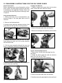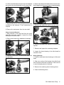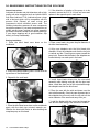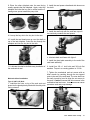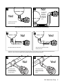
1
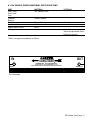
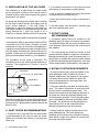
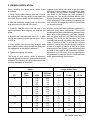
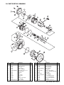
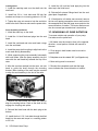
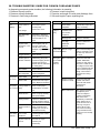
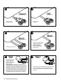
IP 300
IMPORTANT
INSTRUCTIONS
SSV MODEL
VANE PUMPS
SSV 2000
Warning: (1) Periodic inspection and maintenance of Corken products is essential. (2) Inspection, maintenance and installation of Corken products must be made
only by experienced, trained and qualified personnel. (3) Maintenance, use and installation of Corken products must comply with Corken instructions, applicable laws
and safety standards (such as NFPA Pamphlet 58 for LP-Gas and ANSI K61. 1-1972 for Anhydrous Ammonia). (4) Transfer of toxic, dangerous, flammable or explosive
substances using Corken products is at user’s risk and equipment should be operated only by qualified personnel according to applicable laws and safety standards.
The Model and Serial Numbers are shown on the nameplate of the unit. Record this information for future
reference.
Model No.
Serial No.
Date Purchased
Date Installed
Purchased From
Installed By
WARNING
Install, use and maintain this equipment according to Corken’s instructions and all applicable federal, state,
local laws and codes. Periodic inspection and maintenance is essential.
CONTACTING THE FACTORY
Before you contact the factory, note the Model Number and Serial Number of your pump. The Serial Number
directs us to a file containing all information on material specifications and test data applying to your specific
pump. When ordering parts, the Corken Service Manual should be consulted for the proper Part Numbers.
ALWAYS INCLUDE THE MODEL NUMBER AND SERIAL NUMBER WHEN ORDERING PARTS.
TABLE OF CONTENTS
1.
INTRODUCTION TO THE SSV MODEL VANE PUMP ....................................................... Page 4
2.
EXCLUSIVE FEATURES OF THE SSV MODEL VANE PUMP .......................................... Page 4
3.
MECHANICAL SPECIFICATIONS ....................................................................................... Page 4
4.
MATERIAL SPECIFICATIONS............................................................................................. Page 5
5.
INSTALLATION OF THE SSV MODEL VANE PUMP ......................................................... Page 6
6.
INLET PIPING RECOMMENDATIONS ................................................................................ Page 6
7.
OUTLET PIPING RECOMMENDATIONS ............................................................................ Page 6
8.
BY-PASS SYSTEM REQUIREMENTS................................................................................. Page 6
9.
DRIVER INSTALLATION ..................................................................................................... Page 7
10.
MECHANICAL SEAL INSTALLATION ................................................................................ Page 8
11.
PUMP START-UP CHECKLIST ........................................................................................... Page 8
12.
PREVENTATIVE MAINTENANCE ....................................................................................... Page 8
13.
STORAGE ............................................................................................................................ Page 8
14.
PARTS DETAIL DRAWING.................................................................................................. Page 9
15.
DISASSEMBLY OF THE SSV MODEL VANE PUMP ......................................................... Page 10
16.
REASSEMBLY OF THE SSV MODEL VANE PUMP .......................................................... Page 12
17.
REVERSING OF PUMP ROTATION .................................................................................... Page 14
18.
TROUBLESHOOTING ......................................................................................................... Page 15
19.
ILLUSTRATED INSTALLATION TIPS ................................................................................. Page 16
SSV Model Vane Pump 3
1. INTRODUCTION TO THE SSV
MODEL VANE PUMP
The Corken SSV Model Vane Pump is a special type
of rotary positive displacement pump, known as a
sliding vane pump.
The sliding vane pump has many of the advantages
of other rotary positive displacement pumps (i.e.,
gear pumps), plus the ability to compensate for wear
and operate at a lower noise level especially when
pumping light viscosity liquids and liquefied gases.
The sliding vane pump consists of a rotor turning in
a cam (or liner) machined eccentrically in relation to
the rotor; thereby displacing the liquid trapped
between the rotor, cam, and blades (or vanes). The
Corken SSV pumps are made with blades produced
from advanced polymers which exhibit extremely low
coefficients of friction. The blades are self-adjusting
for wear which extends the life of the pump while
maintaining its original efficiency.
• The SSV pump utilizes a mounting bracket so that
it can be direct driven. This bracket eliminates time
consuming alignment procedures and ensures
proper alignment which helps to extend pump and
seal life.
• The SSV incorporates a clean sweep design which
allows for a low residual of liquid to remain in the
pump between cycles. This reduces the potential for
cross contamination when pumping multiple
products.
• The SSV pump accepts most cartridge and
component mechanical seals, which offers sealing
flexibility when application requirements call for a
specific type.
• Replaceable cam (or liner) and sideplates absorb
wear and tear which saves potential costs of
replacing expensive pump components such as
casing.
2. EXCLUSIVE FEATURES OF THE SSV • Direct motor speed capabilities of 1750 and 1150
MODEL VANE PUMP
RPM eliminate the need for costly speed reduction.
In addition to being especially suited for handling
volatile liquids, the SSV pump has a number of
features to help make it more easily operated and
maintained.
• The SSV pump is primarily constructed of 316
stainless steel which enables it to be utilized in a wide
range of applications.
• The SSV's easy back pull-out design allows for
servicing of the entire pumping chamber through
removal of four bolts. This eliminates the need to
disturb piping and driver when maintenance is
required.
3. MECHANICAL SPECIFICATIONS
Specifications
Suction Flange
Discharge Flange
1750 RPM/Nominal Flow Rate/BHP*
1150 RPM/Nominal Flow Rate/BHP*
Minimum Temperature
Maximum Temperature
Maximum Working Pressure
Maximum Differential Pressure
Maximum Viscosity
SSV 2000
2" ANSI 150# FF
2" ANSI 150# FF
60 GPM/3.5 BHP
40 GPM/2.5 BHP
-20° F
225° F
400 psi
100 psi
100 SSU
*Flow and power at listed RPM is based on water at 50 psi differential.
4 SSV Model Vane Pump
SSV 1500
1.5" ANSI 150# FF
1.5" ANSI 150# FF
35 GPM/2.9 BHP
23 GPM/2.0 BHP
-20° F
225° F
400 psi
100 psi
100 SSU
4. SSV SERIES PUMPS MATERIAL SPECIFICATIONS
PART
Case, Head
Rotor Shaft
Cam
Sideplate,
Bearing
Seal Faces
Seal Metal Parts
Blades, Blade Drivers
O-Rings
MATERIAL
316 Stainless Steel
OPTIONAL
Carbon Graphite
Silicon Carbide/Carbon
316 Stainless Steel
PEEK
Viton®
Other Options Available
Aflas, Kalrez,
Teflon® Encapsulated Viton®,
Ethylene Propylene
*Teflon is a registered trademark of Dupont.
IN
CORO-VANE
OUT
CORKEN, INC. A Unit Of IDEX Corp.
OKLAHOMA CITY, OKLAHOMA MADE IN U.S.A.
READ CORKEN INSTRUCTION MANUAL BEFORE OPERATING
MODEL
SERIAL NO
SSV Nameplate
SSV Model Vane Pump 5
5. INSTALLATION OF THE SSV PUMP
The installation of a Vane Pump is a simple matter
but the principles outlined in this manual must be
followed exactly in order that the pump may give the
performance you expect.
No pump can discharge more liquid than it receives
so the pump location and the inlet piping must be
given careful attention. If the inlet piping is
inadequate to supply the demand of the pump you
may expect trouble! It is recommended that the inlet
piping diameter be 1 pipe size larger or at a
minimum, no smaller than the inlet size of the pump.
The pump must be located as near the tank as possible.
Care should be taken to ensure that sufficient NPSH
is provided to the SSV Pump. Although a Corken
vane pump is known for its suction lift capabilities it
is always recommended to provide a flooded suction
with the supply tank above the pump whenever it is
possible. Contact your local Corken representative for
piping recommendations specific to your installation.
The foundation for the pump is important. The
foundation must be firm and level and preferably of
concrete. The suggestions on Figure 1 must be
observed.
Pump Base
1/2” x 8” Anchor Bolt
Metal Shim
2. Use flexible connections in the pump inlet and
outlet piping to compensate for piping strains.
3. Use an eccentric swage at the pump inlet nozzle
to change the line size (flat side up).
4. Make the inlet line level or slope it downward to
the pump.
5. The tank shutoff valve should be a free flow type
and not a standard globe valve.
7. OUTLET PIPING
RECOMMENDATIONS
1. A pressure gauge should be installed in the
discharge piping as close to the pump as possible.
This pressure gauge will tell you the complete story
of the operation inside your pump. Be sure you have
one installed.
2. The outlet piping size should be chosen so that
pressure build up related to restrictions is minimized.
Although outlet piping is not as critical as the inlet, it is
always wise to consider the pressure losses created
by selecting certain piping and accessories. Your local
Corken representative will be helpful in this analysis.
8. BYPASS SYSTEM REQUIREMENTS
1. A pump by-pass system must be installed. If the
pump discharge is shut-off before the driver is
stopped, dangerously high pressures can develop.
A by-pass valve must be installed to permit the
pump to discharge back to the supply tank, at a
predetermined pressure.
Large Washer
Concrete
Figure 1.
After the concrete has set, check the pump base for
level. Drive metal shims under the base near anchor
bolts as shown. Tighten anchor bolts and recheck the
base for level.
6. INLET PIPING RECOMMENDATIONS
1. A strainer of the Y type with 30 to 40 mesh screen
is recommended for the inlet line near the pump.
(Mesh size indicates the number of openings per
lineal inch).
6 SSV Model Vane Pump
2. The pump assembly may have an internal relief
valve. This valve is intended to be used as a relief
device not as an operational bypass valve. The
internal relief valve limits the discharge pressure of
the pump and routes the discharge directly back
into the pumping chamber. During internal bypass
heat is generated as the liquid recirculates within
the pump. The pump can only be operated for a
short period of time in this mode before high
damaging temperatures are encountered.
3. Always install an external by-pass valve in the
pump discharge line. The return piping may
discharge into the tank at any convenient opening,
either liquid or vapor, but it should not connect into
the pump inlet piping system.
9. DRIVER INSTALLATION
When installing the pump driver follow these
procedures.
1. Using a nitrile spider coupling, slide the 1" end of
the coupling over the pump shaft. Do not tighten the
set screw. Place the spider into the coupling end.
2. Slide the remaining coupling end over the motor
shaft until flush with the end of the shaft.
3. Carefully slide the motor into the end of the
mounting bracket while aligning the coupling and
spider.
4. Align the bolt holes and install four 1/2” x 1” bolts
through the mounting bracket into the motor. Torque
to 25 ft. lb.
5. If the coupling ends are not fully engaged, slide
both coupling halves equally toward the spider until
full engagement of the spider is achieved.
6. Tighten the coupling set screws.
The wiring of your electric motor is extremely
important and must be done by a competent electrical
contractor. The following wire size chart indicates the
minimum standards for wire sizes.
Improper motor wiring will cause expensive motor
difficulties from low voltage. If you suspect you have
low voltage, call your Power Company. Connecting
your motor for the voltage you have available is
important too. The motors furnished with the SSV
Pumps are usually dual voltage, so you must be sure
of the voltage your Power Company is supplying you.
Your motor will be completely ruined if it is connected
for the wrong voltage.
A humid climate can cause problems, particularly in
explosion proof motor applications. The normal
breathing of the motor, and alternating between being
warm when running and being cool when stopped,
often will cause moist air to be drawn into the motor
housing. This moist air will condense, and may
eventually add enough free water to the inside of the
motor to cause it to fail. To prevent this, make a
practice of running the motor and pump at least once
a week on a bright, dry day for an hour or so (pump
through the By-Pass System). In this period the motor
will heat up and vaporize the condensed moisture,
and drive it out of the motor. No motor manufacturer
will guarantee an explosion proof or totally enclosed
motor against damage from moisture.
(a) Recommended Wire Size, AWG
Length of Run (Feet)
Motor
HP
3
Motor
Phase
1
3
5
1
3
7-1/2
1
3
10
3
15
3
Volts
115
230
230
460
115
230
230
460
230
230
460
230
460
230
460
Approx.
Full Load
Amperes
34.0
17.0
9.6
4.8
56.0
28.0
15.2
7.6
40.0
22.0
11.0
28.0
14.0
42.0
21.0
0-100
6
12
12
12
4
10
12
12
8
10
12
8
12
6
10
To 200
4
8
12
12
1
6
12
12
6
10
12
8
12
6
10
To 300
2
8
12
12
1/0
4
10
12
4
8
12
8
12
6
10
SSV Model Vane Pump 7
10. MECHANICAL SEAL INSTALLATION 11. If you have both an internal relief valve and an
To install a seal not provided by Corken, follow the
disassembly and reassembly instructions on the
pages 10-14 in conjunction with the seal
manufacturers instructions.
external by-pass valve in your discharge piping, the
internal valve must be set higher than the external by
pass setting.
12. After initial operation, recheck and clear the
strainer screen of any trapped debris.
11. PUMP STARTUP CHECKLIST
Important Note: When incorporating a new SSV
Pump into an application that does not have a
flooded suction and a dry prime must be pulled,
please note that the SSV pump is capable of running
dry for 45 seconds without experiencing damaging
wear (due to the light oil applied at the factory). If the
pump has not primed itself after 45 seconds, please
turn the unit off and prime the pump manually.
12. PREVENTATIVE MAINTENANCE
The following steps must be performed at the initial
operation of your pump.
Pump Maintenance Schedule
Daily
Inspect Drive Coupling
Clean Inlet Strainer
Check for Leaks
X
Inspect Fittings
X
1. Make sure that the proper mechanical seal
is installed.
Your SSV Pump requires regular maintenance and
care like all mechanical equipment. A neglected or
improperly repaired pump will result in premature
failure and/or create an unsafe condition.
Maintenance should only be performed by a properly
trained individual.
Monthly
3 Months
X
X
2. Verify the strainer screen is clean.
3. Check coupling to ensure proper installation.
4. Check motor for proper wiring and rotation.
5. Review the complete piping system to make
certain the function of every valve and piece of
equipment is clearly understood. Everyone operating
this system must be properly trained in normal
operating procedures and emergency procedures in
event of a malfunction.
6. Slowly open the storage tank bottom shut-off valve
(suction line to the pump). Immediately check the
system for leaks.
7. Open any shut-off valves between the by-pass
valve and the storage tank.
8. Make a note of all pressure gauge readings
especially the pressure gauge located at the
discharge of the pump. Start the pump and circulate
the liquid through the by-pass system back to the
storage tank.
9. Verify proper pump rotation direction.
10. Adjust by-pass valve to open at desired pressure
not to exceed the maximum allowable differential of
the SSV Pump.
8 SSV Model Vane Pump
Normal wear parts are the mechanical shaft seal,
bearings, blades, blade drivers and sideplates.
When it becomes necessary to repair your pump or
remove it from the system you must be absolutely
certain that all of the product being pumped is bled
from the pump and connecting piping. Special care
must be taken during the bleeddown process to
avoid danger to personnel and property in the area.
Bleeding a liquefied gas system too fast is a common
mistake and may result in 'refrigerated' liquid being
left in the pump and piping even though a pressure
gauge shows no pressure. As the 'refrigerated' liquid
begins to warm, more gas will escape causing a
dangerous condition. Take your time in bleeding your
system and make proper provisions to vent or
capture the gas in accordance with local regulations.
Only a properly trained individual should ever be
allowed to bleed a pumping system.
13. STORAGE OF SSV VANE PUMPS
If your SSV Pump is to be removed from service for
some time, it would be wise to plug the pump to
ensure that no foreign material enters the pump while
out of operation.
14. PARTS DETAIL DRAWING
13
15
2
14
6
12
9
7
11
10
8
5
4
26
29
3
7
8
2
16
27
19
18
23
20
24
21
25
22
17
15
1
30
28
No
Part No.
Description
1
2
3
4
5
6
7
8
9
10
11
12
13
14
15
4951
2-247
4959
4960
4984
7006-031NC025C
4957
4954
4952
4953
4956-X
4955
2-255
4958
7001-050NC100C
Case
O-ring - Seal Head
Seal Head
Seal Head Key
3/16 x 1/2 Roll Pin
SOC HD Set 5/16-28 x 1/4”
Sleeve Bushing
Sideplate
Cam
Rotor-shaft
Blade Driver
Blade
O-ring - Access Head
Access Head
Bolt - Hex Head
Qty
No
Part No.
Description
1
2
1
1
2
2
2
2
1
1
3
6
1
1
8
16
17
18
19
20
21
22
23
24
25
26
27
28
29
30
4973
2-126
4962
7001-037NC075C
4975
4971-1XDAS
2-226
4969
7201-037C
7001-037NC100C
4974
2-243
2-252
4244
4961
1/4” Pipe Plug
O-ring - RV Cover
Relief Valve Cover
Bolt - Hex Head
Seal Spacer
Type 8-1 Seal Assembly
O-Ring - Gland Plate (with Seal)
Gland Plate
3/8 Flat Washer
Bolt - Hex Head
1/4” Flush Seal Pipe Plug
O-ring - Outer Seal Head
O-ring - Mounting Bracket
Shaft Key
C-Face Mounting Bracket
Qty
3
2
1
4
1
1
1
1
4
4
2
1
1
1
1
SSV Model Vane Pump 9
15. DISASSEMBLY INSTRUCTIONS FOR THE SSV SERIES PUMPS
General Instructions:
Cartridge Seal Removal:
Before attempting any pump disassembly, relieve
pump, jacket, and seal system pressures and drain
in accordance with applicable Federal, State, and
local codes. Be certain all protective clothing is worn,
if required.
1. Replace original seal spacer tabs into the drive
collar. Loosen the drive collar set screws.
Pump Assembly Removal:
1. Before the pump can be disassembled, any
external fittings in the seal gland plate must be
removed.
2. Remove the blind head bolts.
3.Using a pry bar, gently pry between the face of the
gland plate and the top of the mounting bracket.
2. Remove the gland plate bolts and washers.
3. Remove the cartridge seal assembly over the shaft.
4. Support the blind head and cam with one hand
while guiding the shaft end of the pump assembly
with the other hand.
5. Pull the pump assembly through the case and
place on workbench with the blind head facing down.
Type 8-1 Seal Assembly Removal:
1. Remove the 1/4 inch flush seal plugs from the
seal head.
2. Rotate the shaft to align the seal set screws to
each of the 1/4 inch NPT ports.
3. Loosen all set screws in the seal body.
6. Mark the location of the pump shaft coupling and
remove with pump shaft key.
4. Remove the gland plate bolts and washers.
5. Carefully remove the gland plate from the seal head.
10 SSV Model Vane Pump
6. Lift the seal head away from the cam and sideplate
and remove the seal assembly from the seal head.
4. Remove and inspect the blade drivers from the rotorshaft. Inspect for mushroomed ends or external gouging.
7. Tap the seal seat out of the gland plate with a small
screwdriver and hammer if seal replacement is
required.
5. Remove and inspect the cam for uneven wear.
8. Remove the seal spacer from the rotor-shaft.
Pump Component Removal:
1. After removal of the seal head from the pump
assembly previously outlined, inspect the sleeve
bearing for excessive wear.
2. Remove and inspect the sideplate for damage.
6. Remove the blades and inspect for uneven blade
tip wear.
7. Remove and inspect the remaining sideplate.
8. Inspect the sleeve bearing in the blind head for
excessive wear.
3. Vertically remove the rotor-shaft and inspect for
unusual wear.
Bearing Removal:
1. Press the seal head sleeve bearing out of the seal
head.
2. Chip out a section of the bearing in the blind head
with a hammer and small screwdriver. Take care not
to scar the bearing bore in the head.
3. Remove the remaining sleeve bearing pieces.
4. Clean both bearing bores.
SSV Model Vane Pump 11
16. REASSEMBLY INSTRUCTIONS FOR THE SSV PUMP
General Instructions:
Lubricate all threads and pilot diameters with a high
quality anti-seize compound such as Locktite Nickel
Anti-Seize Lubricant 771®. Lubricate all new o-rings
with a lubricant which will be compatible with the
process fluid. Discard all used o-rings and
components which exhibited severe wear. The
following instructions assume all wear components
have been replaced. If your wear components do not
exhibit extreme wear, replace into pump assembly
per these instructions except for the sleeve bearings.
If your sleeve bearings are in good condition, skip
directly to Pump Reassembly.
2. If the direction of rotation of the pump is to be
reversed, remove the 5/16 X 1/4 inch set screw and
replace in the opposite port in each head.
Bearing Installation:
1. Place the blind head nose down on the
workbench.
3. Place a new head o-ring onto the pilot diameter of
the blind head assembly.
4. Align one sideplate onto the blind head pilot
diameter. Orient the sideplate such that the key slot
is vertical and the C faced groove opens toward the
pump inlet. Ensure that the holes in the sideplate are
located directly over each port in the head.
2. Press in the sleeve bearing until it is flush with the
top surface of the blind head.
3. Repeat for the seal head.
5. Install three blade drivers into the rotor-shaft
assembly while holding vertically with the short end
down. Install the short end of the rotor-shaft through
the sideplate and into the blind head.
6. Place the cam with the wide end down over the
rotor-shaft assembly. Orient the cam alignment pin to
the sideplate key slot notch with the key slot on the
outer diameter of the small end away from you.
Pump Reassembly:
1. Place the blind head nose down on the workbench
again with the drain tap oriented towards you.
Stabilize the head with blocks to allow building the
complete pump on this head.
12 SSV Model Vane Pump
7. Install the blades with the curved end toward the
cam and the slots facing in the direction of rotation.
8. Place the other sideplate onto the cam facing
exactly opposite the first sideplate. Again, orient the
sideplate such that the key slot is vertical and the C
faced groove opens toward the pump inlet.
2. Install the seal spacer chamfered side down over
the shaft.
3. Install the seal body with the seal face up until
the seal body contacts the seal spacer.
9. Line up the key slot to the key slot in the cam.
10. Install the seal head nose up over the shaft on
top of the last sideplate. Orient the key through the
sideplate and into the key slot in the cam.
4. Lubricate both seal faces with light oil.
5. Install the gland plate assembly to the end of the
seal head assembly.
11. Lubricate the shaft to facilitate easy installation of
the mechanical seal.
6. Install four 3/8 x 1 inch bolts and 3/8 inch flat
washers. Torque in a crossing pattern to 15 ft-lb.
Mechanical Seal Installation:
7. Tighten the mechanical seal set screws with an
Allen wrench by reaching through the two tapped
ports in the end of the seal head. The rotor-shaft can
be easily turned by hand to align the set screws to
the ports. Caution: Assume that all set screws in the
mechanical seal are loose. Loose screws can cause
premature seal and pump damage.
Type 8-l (4971-1X) Seal:
1. Lubricate the outer o-ring of the seal seat and
press into the gland plate by hand with the shiny side
facing outward.
SSV Model Vane Pump 13
Cartridge Seal:
1. Install the cartridge seal over the shaft onto the
seal head.
2. Install four 3/8 x 1 inch bolts and 3/8 inch flat
washers and torque in a crossing pattern to 15 ft-lb.
3. Tighten the outer set screws to lock the seal drive
collar to the shaft. Remove and save the spacer tabs.
11. Install the 1/4 inch hex head pipe plug into the
drain tap in the blind head.
12. Reinstall all external fittings back into the seal
gland plate if applicable.
13. If the direction of rotation was reversed, remove
the two self tapping nameplate screws and reorient
the nameplate such that the large arrow points in the
correct direction of rotation. The motor rotation must
also be reversed per manufacturer's instructions.
Pump Assembly Continued:
1. Install the shaft key on the shaft.
17. REVERSING OF PUMP ROTATION
2. Install the 1/4 inch flush-seal plugs into the seal
head.
To reverse rotation and operation of your pump,
five tasks must be performed.
3. Install the seal head and outer seal head o-rings
onto the seal head.
1. All blades must be turned to face in the opposite
direction, curved portion of blade still nearest to
the cam.
4. Install the pump shaft coupling to align back to the
mark made during disassembly.
5. While supporting the pump assembly horizontally
with both hands, slide the pump assembly into the
case with the seal head key towards the top of the
case.
6. After the cam has reached into the case, use one
hand to guide the shaft through the mounting
bracket. Minor twisting of the cam may be required
to align the seal head key to the slot in the case.
7. Remove the blind head and rotate the shaft to
align the coupling halves. Push on the shaft to fully
engage the coupling and spider.
9. Reinstall the blind head with the drain plug at the
bottom.
10. Install the four 1/2 X 1 inch bolts through the blind
head into the case and torque in a crossing pattern
to 25 ft.-lb.
14 SSV Model Vane Pump
2. Flush plugs in both heads must be moved to
opposite side.
3. Sideplates must be rotated 180° (not flipped over).
4. Motor wiring must be reversed.
5. Reorient the nameplate such that the large
arrow indicates the correct direction of rotation.
18. TROUBLESHOOTERS GUIDE FOR CORKEN CORO-VANE PUMPS
In
1.
2.
3.
diagnosing pump and system troubles, the following information is essential:
Pressure at pump suction.
4. Pressure in tank being filled.
Pressure at pump discharge.
5. Pipe size and length of suction and discharge lines.
Pressure in tank being evacuated.
6. Size and length of vapor equalizing line.
PROBLEM
CAUSE
WHAT TO DO
Low
capacity
Pump speed too
slow
Check motor speed.
Consult pump
performance curve.
Low voltage
High differential
pressure
By-pass valve
stuck open or set
too low
Pump runs
but no flow
Won’t build
pressure
Pump is
noisy
Restriction in discharge
piping or discharge piping
hose too small or not
used.
Check capacity with bypass line closed with
manual valve. Use care:
Readjust, repair or replace
valve.
Clogged strainer
Clean strainer.
Suction pipe too
small or restricted
Indicated by pump inlet
pressure dropping several
pounds when pump is
started. Remove restriction
or modify piping.
Worn blades
Replace blades.
Worn sideplates
Replace sideplates.
Valve closed
Open valve.
Broken shaft
Disassemble and inspect
pump. Repair if necessary.
Pump won’t Foreign matter in
turn—locked pump
PROBLEM
Clean out the pump—
install strainer on suction
line.
Blades broken
Clean out pump carefully
and replace blades.
Bearing seized
Inspect for additional
damage. Replace bearing
and other parts as needed.
Moisture frozen in
pump
Thaw and break loose
carefully. (Do not use an
open flame to thaw.)
Poor suction
conditions
Increase pipe size. Clean
inlet strainer.
By-pass valve set
too low
Set valve for higher
pressure (see
instructions).
CAUSE
WHAT TO DO
Worn blades,
sideplates
Disassemble, inspect and
repair if necessary.
Cavitation from
poor suction
conditions
As above.
Bearings bad
Replace if necessary.
Very high
differential
pressure
Check for restriction in
discharge line.
Pump leaks Seal or o-rings
around shaft failed
Inspect seal assembly and
replace if necessary. Keep
new seal very clean and
oil o-rings.
Motor overloaded
Motor gets
hot or switch
overload
kicks out
Check motor load with
ammeter. Differential
pressure too high. Set bypass lower—check for low
line voltage at motor while
pump is operating. Be sure
motor is wired for proper
voltage. Consult motor
name-plate and wiring
diagram.
Starter overload
heaters too small
Check motor load with
ammeter and confirm
heater size with starter
manufacturer’s
instructions.
Motor shorted out
TEFC (totally enclosed)
and explosion proof
motors are subject to
moisture condensation
inside when used
intermittently. To eliminate
trouble, allow motor to
operate at least once a
week long enough for
motor to get hot. This
would not be necessary
during off seasons when
equipment is not normally
operating.
SSV Model Vane Pump 15
19. ILLUSTRATED INSTALLATION TIPS
1
No!
2
Yes!
Use inlet line larger than pump
suction nozzle. Same size as
nozzle OK on short runs.
Don't use restricted inlet line!
Pressure drop caused by restriction in suction line will cause vaporization and cavitation.
3
No!
4
Yes!
Eccentric Reducer.
Concentric Reducer
An eccentric reducer should always be used when reducing into any pump inlet where vapor might be encountered in the pumpage. The flat
upper portion of the reducer prevents an accumulation of vapor that could interfere with pumping action.
5
No!
6
Yes!
10D
D
Don't locate restrictive fittings
or elbows close to pump inlet.
Best rule is 10 pipe diameters
straight pipe upstream from
pump! (not always possible)
Turbulence caused by flow interference close to the pump accentuates incipiant cavitation.
16 SSV Model Vane Pump
7
No!
8
Try not to locate
pump above
level of liquid
feeding pump.
Product must
be able to flow
by gravity into
pump.
Yes!
Locate pump close to tank!
Directly under is best.
When possible, it is best to allow the pump to be fed by gravity flow to give stable, trouble-free operation.
9
10
No!
Yes!
Don't slope liquid line up toward pump!
Slight slope down toward pump is best.
Perfectly level is OK.
Vaporization in the pump inlet line can displace liquid in the pump so that pump may start up in a dry condtition. A slope back toward the tank of
only an inch or two in a 10 foot run will allow vapor to gravitate back into the tank and be replaced with liquid.
11
12
ine
in L
a
M
No!
When feeding small
pump from large main
line, don't tee off the side.
Tee out the bottom!
e
Lin
n
i
Ma
Yes!
When feeding a small
pump from a tee off of a
large pipe, come out the
bottom.
SSV Model Vane Pump 17
13
14
Good...
Multiple pumps fed
from same main line.
15
OK...
Pumps operating
in parallel.
No!
16
Yes!
Best...
Parallel piping of SSV pumps.
17
No!
Don't pipe bypass line back
into suction piping! Heat
buildup in recirculated
products causes flashing of
liquid to vapor with
immediate cavitation and ultimate dry-running. This is why the
bypass relief valves which are built into many positive displacement
pumps should not be used for normal bypass action when handling
liquefied gases. The internal valve should be considered to be a
back-up safety relief in addition to a back-to-tank bypass valve and
should be set to relieve at a pressure 10 to 20 psi higher than the
working bypass. Some built-in bypass valves have the capability of
being piped back-to-tank so check with the pump manufacturer.
18 SSV Model Vane Pump
Bad...
Pump No. 1 is starved because
of venturi action at tee. This
would be acceptable for
installations where both
pumps would never operate
at the same time.
18
Yes!
Always pipe bypass back to tank! Make sure bypass line is large
enough to handle full pump flow without excessive pressure
build-up. High pressure rise can cause bypass valve to chatter
and vibrate.
SSV Model Vane Pump 19
P.O. Box 12338, Oklahoma City, OK 73157
3805 N.W. 36th St., Oklahoma City, OK 73112
Phone (405) 946-5576 • Fax (405) 948-7343
E-mail [email protected]
Web address www.corken.com
Printed in U.S.A.
May 1998