1
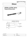
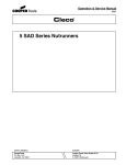
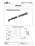
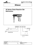
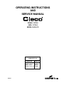
OPERATING INSTRUCTIONS
AND
SERVICE MANUAL
55NAL-1-270-4
55NL-1-724-4
55RNL-2-LS-4-13
COMPLETE TOOL
MODEL NO.
READ SAFETY
823231
CODE NO.
55NAL-1-270-4
230270
55NL-1-724-4
220724
RECOMMENDATIONS
BEFORE
55RNL-2-LS-4-13 240389
OPERATING TOOL
OPERATING INSTRUCTIONS
55 CLECOMATIC NUTRUNNERS
The 55 Clecomatic nutrunner is designed to operate on 90
psig maximum air pressure but does not depend on
controlled air pressure to maintain accurate torque. Accurate torque is achieved by setting the Clecomatic clutch to
the desired torque on the application. The tool will shut off
automatically at this torque. Releasing the throttle will
allow the tool to reset for the next cycle.
If the clutch is adjusted over the maximum power output of the tool, the clutch
will not function and the tool will operate like a stall-type
tool. Also, if the tool is being operated at its upper torque
limits, a drop in air pressure could cause the clutch not to
function due to a loss of motor power and the tool will
function like a stall-type tool. If the tool stalls the operator
must resist the stall torque until he releases the throttle.
!
CAUTION
Operational check: Grip tool securely and be prepared to
counteract stall torque in case clutch is improperly adjusted. THIS IS A HIGH TORQUE TOOL.
CLECOMATIC CLUTCH ADJUSTMENT
Depress the pin, No. 864711, and rotate the adjustment
cover, No. 867677, 180 degrees so it lines up with the
adjustment slot. With the angle head end of the tool facing
outward, away from the operator, use a 1/8" diameter pin
to rotate the adjustment nut, No. 867678, clockwise to
increase the torque and counterclockwise to decrease the
torque. Note: The steel ball, No. 844077, is a positive lock
for the adjustment nut and must be in place in a locking slot
before the adjusting cover is rotated to the locked position
after each clutch adjustment is completed.
METERING VALVE
The metering nut No. 203203, can be adjusted with a hex
wrench clockwise to lower the RPM of the tool or counterclockwise to raise the RPM of the tool.
THROTTLE POSITION
The throttle lever or button may be repositioned to
accomodate proper location for task and to avoid entrapment. Repositioning of the angle head is done by loosening housing lock nut No. 867521, and lifting the angle head
until the spline on the angle head clears the gear case and
can be rotated to the position desired. Lower the angle
head back into place and tighten housing lock nut.
AIR SUPPLY
For maximum performance, use a 1/2" I.D. air hose no
longer than 8' in length. If additional length is required, a 5/
8" or larger hose should be connected to the 1/2" hose.
The air hose should be cleared of accumulated dirt and
moisture, then one (1) teaspoon of 10W machine oil
should be poured into the tool's air inlet before connecting
the hose to the tool.
LUBRICATION
An automatic in-line filter-lubricator is recommended as it
increases tool life and keeps the tool in sustained operation. The in-line lubricator should be regularly checked and
filled with a good grade of 10W machine oil. Proper
adjustment of the in-line lubricator is performed by placing
a sheet of paper next to the exhaust ports and holding the
throttle open approximately 30 seconds. The lubricator is
properly set when a light stain of oil collects on the paper.
Excessive amounts of oil should be avoided.
Application of the tool should govern how frequently it is
greased. It is recommended that the idler gears receive a
generous amount of No. 2 Moly grease when tool is
disassembled.
STORAGE
In the event that it becomes necessary to store the tool for
an extended period of time (overnight, weekend, etc.), it
should receive a generous amount of lubrication at that
time and again when returned to service. The tool should
be stored in a clean and dry environment.
SERVICE INSTRUCTIONS
DISASSEMBLY — GENERAL—Stall Tools
To disassemble the tool, clamp the spindle housing adaptor lightly in a soft-jawed vise with the tool in a horizontal
position. Using a suitable wrench, unscrew the motor
housing. Using a suitable wrench, unscrew the spindle
housing (left hand threads). Be careful not to lose any gear
train components. Using a soft-faced mallet, tap the front
of the motor housing to remove the motor unit.
Automatic Shut-Off Tools
To disassemble the tool, clamp the flats of the clutch
housing in a soft-jawed vise and unscrew the motor
housing. Clamp the spindle housing adaptor in the vise
and unscrew the spindle housing (left hand threads).
Using a suitable wrench, unscrew the clutch housing from
the spindle housing adaptor. Be careful not to lose any
gear train components. Tap the front of the motor housing
with a soft-faced mallet to remove the motor unit.
2
SUBASSEMBLY DISASSEMBLY
Gear Train
Clamp spindle housing adaptor, in vise and uncrew spindle
housing (left hand threads). Remove spider 869905, out
rear of spindle housing. Remove bearing retainer 869877
and bearing retainer ring 882115, to release spindle.
Clamp clutch housing in vise (if tool is equipped with
clutch) and unscrew spindle housing adaptor 203696. 1st
reduction spider 861485, will fall out rear. The 2nd reduction spider 203698, can now be removed from bearing
865198. The bearing can also be removed for inspection.
By driving the idler gear pins out of the rear of the spiders,
the idler gears can be removed from the spider pockets.
Clecomatic Clutch
Remove the adjustment cover by sliding it off the back of
the clutch housing. Be careful not to lose the steel ball, No.
844077, that will drop out at this time. Using the slots
provided on the rear face of the adjusting nut, No. 867678,
unscrew it from the clutch housing. The torque spring
bearing, No. 867683, spring plate, No. 867669, and torque
spring, No. 869626, will come out through the rear of the
clutch housing. With a soft mallet, tap on the gear end of
the clutch to remove it from the clutch housing. By removing the retainer ring, No. 847022, the drive shaft washer,
No. 867666, trip sleeve spring, No. 202056, trip sleeve,
No. 867670 and two (2) steel balls, No. 842161, can be
removed from the drive shaft. Remove the clutch cam
bearing, No. 619377, with a suitable puller. Using a sharp
instrument, remove the spiral ring, No. 865436. This will
allow the clutch cam, No. 867676, three (3) steel balls, No.
842161, trip plunger spring, No. 867671 and trip plunger,
No. 867668, to be removed through the front of the drive
shaft. To remove the six (6) steel balls, No. 844265, slide
the ball retainer, No. 867673, off over the rear of the drive
shaft.
Motor Unit
Remove bearing cap. Clamp the cylinder lightly in the vise
with the gear end of the rotor up. Note: The rotor pinion, No.
867524, used on the -4 and -6 models should be removed
at this time. Drive the rotor out of the front rotor bearing, No.
619377. Be careful not to damage the rotor. The front
bearing plate, No. 867536, cylinder, and rotor blades, can
now be removed from the rotor. Clamp the body of the rotor
in the vise with the rear bearing plate up. After unscrewing
the bearing lock nut, No. 865352, the rotor can be driven
out of the rear rotor bearing.
would indicate a brinelled condition. The rotor blades
should be replaced at every repair cycle or if they measure
less than 1/4" at either end. All gear teeth, bearings, and
pins should receive a close inspection and be replaced if
necessary.
Motor Reassembly
To assemble the motor, install the rear rotor bearing into
the rear bearing plate. Make sure the outer bearing race is
firmly seated in the bearing plate. Clamp the rotor body
lightly in the vise with the threaded end up and slip the rear
bearing plate assembly onto the rotor shaft far enough for
the bearing lock nut to start. Tighten the lock nut until there
is approximately .0015" clearance between the rotor and
bearing plate. The outer bearing race should be firmly
seated and the rotor bumped forward when checking this
clearance. Pack both rotor bearings with a good grade of
No. 2 Moly grease after assembly of the motor unit. Note:
During reassembly of the complete tool, it is important that
the motor be free. After the tool is completely assembled,
the right angle square drive spindle should turn freely
using a small hand wrench. If the spindle does not turn
freely, the motor should be checked for proper spacing. Do
not run the tool until the spindle turns freely. Failure to do
this could result in damage to motor components.
During reassembly of the gear train and head, all of the
various gears and bearings should receive a generous
amount of No. 2 Moly grease.
The Clecomatic clutch is assembled in the reverse order
of disassembly. The torque spring bearing, No. 867683,
must be assembled so the solid side of the ball separator
is facing toward the torque spring.
During reassembly on the automatic shut-off tools, the tip
rod must be ground flush (+0 to -1/32) with the hex end of
the rotor. Hold the motor firmly in the housing at the time
the trip rod is being sized to length.
Pour a few drops of 10W machine oil into the air inlet after
complete assembly to insure immediate lubrication of all
motor parts when air is applied.
SAFETY CHECK
After repair or replacement of parts, tools equipped with an
automatic shut-off device should be tested to verify that
they are functioning properly.
REASSEMBLY
The tool is reassembled in the reverse order of disassembly. Clean all parts thoroughly in a solvent and inspect for
damage or wear. Check all bearings for wear which can be
detected by excessive end play and/or roughness which
3
NO. 55NAL-1 & 55NL-1 NUTRUNNER GEAR TRAINS
203062-5
869907-9 (13 PER GEAR)
864671-3
869908-4
869903-5
203107-8
832125-9
203696-4
844774-0
867526-6
203699-4
865198-6
869905-0
203698-9
861485-1
869877-1
203137-5 - 1/2" SQ. DR.
NO RETAINER
844011-7
844014-1
844010-9
202533-6
882115-9
202536-9
203697-8
619466-6
PARTS LIST — GEAR TRAIN
PART NO.
NAME OF PART
202533
202536
203062
203107
203137
203696
203697
203698
203699
619466
832125
844010
844011
Spindle (incl. 844010, 844011 & 844014)
Spindle Needle Bearing
2nd Red. Idler Gear Bearing
2nd Red. Idler Gear-15T (incl. 203062)
Spindle
Spindle Housing Adaptor
Spindle Housing
2nd Red. Spider-19T
Retainer Ring
Spindle Ball Bearing
1st Red. Gear Pin
Spring Retainer
Socket Lock Pin
QTY. PART NO.
1
1
6
3
1
1
1
1
1
1
3
1
1
844014
844774
861485
864671
865198
867526
869877
869903
869905
869907
869908
882115
NAME OF PART
Lock Pin Spring
1st Red. Idler Gear Bearing
1st Red. Spider-19T (incl. 832125)
2nd Red. Idler Gear Pin
2nd Red. Spider Ball Bearing
1st Red. Idler Gear Bearing-21T
(incl. 844774)
Spindle Ball Bearing Retainer Ring
3rd Red. Idler Gear-15T
3rd Red. Spider
3rd Red. Needle Roller
3rd Red. Idler Gear Pin
Spindle Retainer Ring
QTY.
1
3
1
3
1
3
1
3
1
39
3
1
4
NO. 55 NAL-1 CLECOMATIC CLUTCH
869263
867681
864711
867677
844077
864712
619377
867676
867671
867668
842161
844265
847022
865436
867674
842161
869626
867670
867673
867669
867683
202056
867666
867678
PARTS LIST — CLECOMATIC CLUTCH
PART NO.
202056
619377
842161
844077
844265
847022
864711
864712
865436
867666
867668
867669
NAME OF PART
TRIP SLEEVE SPRING
CLUTCH CAM BEARING
STEEL BALL 3/16" DIA.
STEEL BALL 5/16" DIA.
STEEL BALL 1/8" DIA.
WASHER RETAINER RING
PIN
PIN SPRING
SPIRAL RING
DRIVE SHAFT WASHER
TRIP PLUNGER
TORQUE SPRING PLATE
QTY. PART NO.
1
1
5
1
6
1
1
1
1
1
1
1
867670
867671
867673
867674
867676
867677
867678
867681
867683
869263
869626
NAME OF PART
TRIP SLEEVE
TRIP PLUNGER SPRING
BALL RETAINER
DRIVE SHAFT
CLUTCH CAM
ADJUSTMENT HOLE COVER
ADJUSTMENT NUT
CLUTCH HOUSING (INCL. 864711,
864712, 869263)
TORQUE SPRING BEARING
PIN SLEEVE
TORQUE SPRING
QTY.
1
1
1
1
1
1
1
1
1
1
1
The complete clutch with housing can be purchased as a sub-assembly using Part No. 861847.
5
NO. 55NAL-1 & 55NL-1 MOTOR
Non-Reversible Tools (Round Rotor)
203102-9 Stall Tools
203100-3 Automatic Shut-off Tools
812165-9 Rev.
863887-6 Non-Rev.
Reversible Tools (Star Rotor)
869573-6 Stall Tools
869570-2 Automatic Shut-off Tools
867536-5
843444-1 Non-Rev.
847096-5
Rev.
847603-8
Rev. Models Only
865352-9
619377-5
869569-4
203101-1 Non-Rev.
203103-7
Rev.
869572-8 Non-Rev.
869660-1
Rev.
869059-6
Stall Tools
Only
203989-9
Stall Tools
Only
863468-5
Automatic Shut-off
Tools Only
PARTS LIST — MOTOR
PART NO.
203100
203101
203102
203103
203989
619377
812165
843444
847096
847603
863468
863887
865352
867536
869059
869569
869660
869570
869572
869573
NAME OF PART
ROTOR-HEX (NON-REV. AUTOMATIC SHUT-OFF)
CYLINDER (NON-REVERSIBLE) - INCL. 8863887
ROTOR-7T (NON-REVERSIBLE STALL)
CYLINDER (REVERSIBLE) - INCL. 812164
BEARING CAP (STALL TOOL ONLY)
FRONT ROTOR BEARING
REVERSIBLE CYLINDER PIN
REAR ROTOR BEARING (NON-REVERSIBLE)
REAR ROTOR BEARING (REVERSIBLE)
ALIGNMENT PIN (REVERSIBLE)
TRIP ROD (AUTOMATIC SHUT-OFF)
NON-REVERSIBLE CYLINDER PIN
ROTOR LOCK NUT
FRONT BEARING PLATE
MOTOR SPACER (STALL ONLY)
ROTOR BLADE
REAR BEARING PLATE (REVERSIBLE)
ROTOR-HEX (REVERSIBLE AUTOMATIC SHUT-OFF)
REAR BEARING PLATE (NON-REVERSIBLE)
ROTOR-7T (REVERSIBLE STALL)
QTY.
1
1
1
1
1
1
1
1
1
1
1
1
1
1
1
5
1
1
1
1
6
NO. 55 NAL-1 & NL-1 HANDLE
LOCK-OFF-201638
LEVER
202105
845409
204178
203110
203111
869855
Non-Reversible
Reversible
863468
864195
865063
Automatic Shut-off Tools Only
202481
867554
867682
Reversible Only
Non-reversible
Automatic
Shut-off
Tools Only
847275
867667
869659
869655
619164
867667
Clecomatic Only
202011
Reversible Tools Only
622062
202055
869931
617754
203109
202632
843656
864973
202626
622881
202508
202628
Reversible Only
832079
203202
203203
PARTS LIST — HANDLE
PART NO.
202011
202055
202105
202481
202508
202626
202628
202632
203109
203110
203111
203202
203203
204178
617754
619164
622062
NAME OF PART
SEAL RING
THROTTLE VALVE
LOCK-OFF LEVER PAWL
THROTTLE VALVE PIN
INLET SPACER
EXHAUST DEFLECTOR
REVERSING VALVE SLEEVE
MUFFLER
MUFFLER
MOTOR HOUSING (NON-REV.)
MOTOR HOUSING (REV.)
INLET BUSHING
METERING NUT
LOCK-OFF LEVER
"O"-RING 2" X 2-1/8"
"O"-RING 1-9/16" X 1-3/4"
"O"-RING 7/8" X 1-1/16"
QTY.
PART NO.
NAME OF PART
QTY.
1
1
1
1
1
1
1
1
1
1
1
1
1
1
2
1
1
622881
832079
843656
845409
847275*
863468*
864195
864973
865063
867554
867667*
867682*
869655
869659
869855
869931
"O"-RING 7/8" X 1-1/8"
SPRlNG
AIR INLET SCREEN
LOCK-OFF LEVER PAWL RETAINER PIN
"O"-RING 1-1/16" X 1-3/16"
TRIP ROD
LEVER PIN
THROTTLE VALVE SPRING
THROTTLE LEVER
REVERSING VALVE SCREW
SHUT-OFF VALVE
VALVE BLOCK
MOTOR SPACER
REVERSING VALVE
LOCK-OFF LEVER SPRING
THROTTLE VALVE SEAT
1
1
1
1
1
1
1
1
1
1
1
1
1
1
1
1
* Denotes parts not included in subassemblies listed below.
7
55NL-1-724
PART NO.
202011
202055
202105
202481
202508
202536
202626
202632
203101
203102
203107
203109
203110
203137
203696
203697
203698
203699
203989
204178
617754
619377
619466
622062
622881
843444
843656
845409
861485
864195
864671
864973
865198
865352
867526
867536
869059
869569
869572
869855
869877
869903
869905
869907
869908
869931
869933
882115
NAME OF PART
SEAL RING
VALVE, THROTTLE
TOGGLE
T.V. PIN
INLET SPACER
SPINDLE BEARING
DEFLECTOR, EXHAUST
MUFFLER
CYLINDER
ROTOR
IDLER GEAR, 2ND RED.
MUFFLER
HANDLE
SPINDLE
GEAR CASE
GEAR CASE
2ND. RED. SPIDER
RETAINING RING
BEARING CAP
LOCK-OFF LEVER
RING, O
BEARING, BALL
BEARING, BALL
RING, O
RING, O
BEARING, BALL
SCREEN
PIN, SPRING
SPIDER, OPEN
PIN, SLOTTED SPRING
PIN, DOWEL
SPRING
BEARING, BALL
NUT, LOCK
IDLER GEAR 121T)
PLATE, FRONT BEARING
MOTOR SPACER
BLADE, ROTOR
PLATE, REAR BEARING
TOGGLE SPRING
BEARING RETAINER
GEAR, IDLER
SPIDER, CAGE
ROLLER, NEEDLE
SHAFT, GEAR
THROTTLE VALVE SEAT
INLET BUSHING
RETAINER RING
QTY.
1
1
1
1
1
1
1
1
1
1
3
1
1
1
1
1
1
1
1
1
2
1
1
1
1
1
1
1
1
1
3
1
1
1
3
1
1
5
1
1
1
3
1
39
3
1
1
1