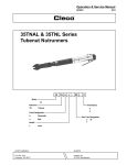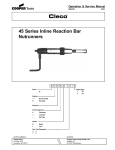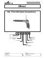
1
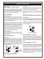
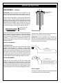
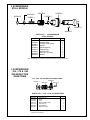
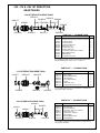
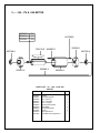
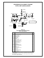
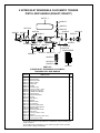
Operation & Service Manual
823197
2/01
104, 174 & 254 Series Screwdrivers
5
XX
A X TP - XXX B - Q
Tool Type:
RS
Rev. Slide Screwdriver
Torque Control Mechanism:
A
Clecomatic
U Top Air Inlet
B
Output Drive:
Quick Change
Q
Generation:
Second
Gear Train Designation:
104 174 254
Handle:
TP
Pistol (Trigger Start)
NORTH AMERICA
EUROPE
CooperTools
P.O. Box 1410
Lexington, SC 29071
Cooper Power Tools GmbH & Co.
Postfach 30
D-73461 Westhausen
1
OPERATING INSTRUCTIONS
READ SAFETY RECOMMENDATIONS BEFORE
CONNECTING TOOL.
The tool is designed to operate at 90 psig (6.2 bar) air
pressure. The air pressure should be checked at the tool's
air inlet while the tool is running.
OPERATION
CLECOMATIC Models
No. 5 Series CLECOMATIC screwdrivers are automatic
shut-off tools. Accurate torque is achieved by setting the
CLECOMATIC clutch to the desired torque. The tool will
automatically shut off at this preset torque.
The use of an automatic in-line filter-regulator-lubricator is
highly recommended. This will supply the tool with clean,
lubricated air, keep it in sustained operation, and increase
tool life.
The RSATP model is designed to start when the trigger is
pulled and stops when the clutch reaches the set torque or
the trigger is released. Releasing the trigger will reset the tool
for the next cycle.
For maximum performance, use a 1/4" (6.5mm) I.D. air hose
up to 8 feet in length. If additional length is required, a 3/8"
(9.5mm) I.D. or larger hose should be connected to the
1/
4" (6.5mm) I.D. hose.
CLUTCH ADJUSTMENT
The air hose should be cleared of accumulated dirt and
moisture, then one-quarter (1/4) teaspoon (6.5cc) of 10W
machine oil should be poured into the tool's air inlet before
connecting the hose to the tool.
The clutch is adjusted through the slot provided in the clutch
housing. The slot cover will have to be rotated to expose the
adjustment slot. Rotate the clutch until the hole in the
adjustment lock plate is visible. Insert a No. 1 Phillips
screwdriver and rotate in a clockwise direction to increase
the torque setting or a counterclockwise direction to decrease the setting.
!
If the clutch is adjusted over the maxi-
CAUTION mum power output of the tool, the clutch
will not function and the tool will operate like a stall-type tool.
Also, if the tool is being operated at its upper torque limits, a
drop in air pressure could cause the clutch not to function
due to a loss of motor power and the tool will function like a
stall-type tool. If tool stalls, operator must resist stall torque
until throttle is released.
Operational check: Grip tool securely and be prepared to
counteract stall torque in case clutch is improperly adjusted.
2
AIR SUPPLY
LUBRICATION
The in-line lubricator should be checked regularly and filled
with a good grade of 10W machine oil. In the event a line
lubricator is not used, tools should be disconnected from the
air supply several times daily and several drops of oil poured
into the tool's inlet bushing.
Application of the tool should govern how frequently it is
greased. It is recommended that the idler gears receive a
generous amount of NLGI 2-EP grease after every 40 hours
of operation. The clutch housing (left hand threads) and
clutch must be removed and the grease applied through the
hex in the spider.
SERVICE INSTRUCTIONS
DISASSEMBLY - GENERAL (All Models)
Clamp the handle in a soft-jawed vise and using a wrench
unscrew the quick change chuck (left hand threads). Unscrew the clutch housing from gear case. Unscrew and
remove the gear case assembly from the handle. The motor
unit may now be removed from the backhead.
CLUTCH DISASSEMBLY
Clecomatic Clutch:
Unscrew (left hand threads) the adjustment nut 869123, and
remove the adjustment lock ring 869140. The torque spring,
bearing races 863455, thrust bearing 847104, ball retainer,
203573, and four (4) steel balls 842161, may now be
removed from the clutch spindle.
Washing the remaining spindle asembly in a solvent will aid
disassembly. Remove the ball retainer ring 203574, and ball
retainer plug 869149, from the clutch cam 203572. Rotate
the clutch spindle, to allow the thirteen (13) steel balls
842980, to drop out of the ball loading hole located in the
clutch cam. Separate the clutch spindle and clutch cam,
being careful not to lose the reset pin 869112, reset spring
203585, reset pin stop 869424, trip slide 203612, trip slide
reset spring 203613, and dowel pin 617226.
Quick Change Chuck
Removing retainer ring 833688, will release all parts in the
quick change chuck. The rest of the clutch disassembles the
same as finder clutch.
GEAR TRAIN DISASSEMBLY
-104 Gear Train
Spiders should be removed from the rear of the gear case.
Remove the bearing retainer ring 619017 and press the
spider bearing 847595, out the front of the gear case. If
replacement of the idler gear pins is necessary, they should
be pressed out the rear of the spider. If replacement of the
first reduction spider pinion 869132 is necessary, if should
be pressed out the front of the spider. See Figure 1 for
replacement dimensions.
.222
(5.64mm)
.218
(5.54mm)
.225
(5.72mm)
.220
(5.59mm)
Front
Front
Rear
Rear
Pinion should be
pressed in flush
to .005 (1.27mm)
below surface.
2nd Red. Spider
1st Red. Spider
Fig. 1: -104 Gear Spider Gear Train:
-174 Gear Train
When pressing the spider assembly out of the rear of the
gear case 869162, be sure the idler gears 869163, are in line
with the pockets machined in the gear case.
Press the idler gear pins 833862, out the rear of the spider
869155, for inspection of the idler gear pins and idler gears
869163.
Remove the bearing retainer ring 619017, and press the
front spider bearing 847595, out the front of the gear case.
-254 Gear Train:
Press the spider assembly out the rear of the gear case.
Remove the bearing retainer ring 619017, and press the
front spider bearing 847595, out the front of the gear case.
If replacement of the idler gear pins, is necessary, they
should be pressed out the rear of the spider. See Figure 2 for
replacement pin height.
.225
(5.72mm)
.220
(5.59mm)
Front
Rear
Fig. 2: -254 Gear Spider
MOTOR DISASSEMBLY — (All Models)
Slip the front bearing 842768, and front bearing plate 203641,
off the front of the rotor and remove the cylinder 203504, and
four (4) rotor blades 203615. Set the rear bearing plate on
the vise jaws with the rotor hanging down. Use a 3/16"
(4.8mm) punch to drive the rotor out of the rear rotor bearing
842768.
HANDLE DISASSEMBLY — (All Models)
For inspection or replacement of the throttle valve or related
parts, rol down the grip sleeve and drive trigger bushing
retainer pin out and removing bushing. Shut off valve and
seal can be removed by removing 203559 valve cap.
The reversing valve may be removed by first unscrewing the
reversing valve screw out of the reversing valve knob. Then
reversing valve may be removed from the handle. On
reassembly make sure the reversing valve screw aligns with
the threaded hole in reversing valve.
3
SERVICE INSTRUCTIONS
REASSEMBLY — GENERAL
.0015" (.038mm)
Clearance
IMPORTANT: During reassembly of the complete tool, the
gear case should be tightened to the handle to 20 ft. lbs.
(27Nm). Wrenches can be ordered for performing this task.
All parts should be washed in a solvent and inspected for
damage or wear. Particular attention should be given to all
bearings, gears, gear pins, and rotor blades as failure of these
parts could cause damage to more expensive parts. Rotor
blades should be replaced if they measure less than 1/8"
(3.2mm) on either end. Rotor blades should be sized in length
to .003"/.004" (.08mm/.10mm) shorter than the cylinder.
Replace blade if less
than 1/8"(3.2mm)
on either end.
TRIP ROD SIZING
Inspect and replace any "O"-rings or seals that show signs of
wear of deterioration. All gears, gear pins, and open bearings
should receive a generous amount of NLGI 2-EP grease
during reassembly. Reassembly of all of the various subassemblies is in reverse order of disassembly: however, the
following paragraphs list some of the more important reassembly procedures.
The trip rod No. 203586, should be sized to allow approximately 1/8" (3.2mm) throttle valve opening.
IMPORTANT: During reassembly of the complete tool,
gear case should be tightened to handle to 20 ft. lbs.
(27Nm). Wrenches shown below can be ordered to tighten
the gear case and clutch housing.
CLUTCH REASSEMBLY
Clecomatic Clutch:
During reassembly of the clutch, all parts should receive a thin
coating of 10W machine oil. In addition, the ball retainer
203573, should receive a generous amount of NLGI 2-EP
grease. When installing the dowl pin 617226, the tapered end
goes into the clutch cam first. The trip slide 203612, goes into
the clutch cam cupped-end first. All parts installed into the
clutch spindle and clutch cam 203572, should be checked for
smooth operation before complete assembly of the clutch.
203803-2
GEAR CASE WRENCH
34 204 - ARMSTRONG U.S.A.
MOTOR REASSEMBLY
203804-0
CLUTCH HOUSING WRENCH
Install the rear rotor bearing, into the rear bearing plate
203506. If using new parts, check for burrs or nicks. After
installing new cylinder pins, check for burrs around pins. Press
the bearing plate assembly (press on the bearing's inner race)
onto the rear rotor shaft until there is approximately .0015"
(.04mm) clearance between the rear bearing plate and rotor.
C
471
3/4 - 2
SAFETY CHECK
After repair or replacement of parts, tools should be tested
to verify that they are functioning properly.
4
5 SCREWDRIVER
STALL SPINDLE
202833-0
864249-8
833688-5
203622-6
619524-2
202842-1
202847-0
844265-9
PARTS LIST — 5 SCREWDRIVER
STALL SPINDLE
Name of Part
Part No.
202833-0
202842-1
202847-0
203622-6
619524-2
833688-5
844265-9
864249-8
Release Collar
Release Collar Spring
Spindle
Spindle Housing
Retainer Ring
Retainer Ring
Ball (1/8"/ 3.175mm)
Washer
Qty.
1
1
1
1
1
1
1
1
The complete clutch can be purchased using this number: 201219-3
5 SCREWDRIVER
-104, -174 & -254
2ND REDUCTION
GEAR TRAIN
-104, -174 & -254 2ND REDUCTION GEAR TRAIN
203623-4
619017-7
844111-5
869135-4
847595-6
204282-8
PARTS LIST — -104, -174 & -254 GEAR TRAIN
PART NO.
203623-4
203978-2
204282-8
619017-7
844111-5
847595-6
869135-4
NAME OF PART
Idler Gear (14T)
Spider
Cage
Bearing Retainer Ring
Idler Gear Pin
Spider Bearing
Gear Case (41T)
QTY.
3
1
1
1
3
1
1
The complete gear train can be purchased as a subassembly
using part no. 201659-0.
5
5 CLECOMATIC CLUTCH
FOR -104, -174 & -254
619017-7* 847095-7*
203584-8*
203626-7*
863455-2
863455-2
869140-4
847104-7
869123-0
203580-6
203579-8
203575-6
203578-0
Blue
Green
White
Yellow
203625-9
203589-7
842161-2
203573-1
617226-6 869112-3
869424-2
203572-3
203585-5
203612-7
203613-5
869149-5
203574-9
842980-5
Part No.
203572-3
203573-1
203574-9
203575-6
203578-0
203579-8
203580-6
203584-8
203585-5
203589-7
203612-7
203613-5
203625-9
203626-7
617226-6
PARTS LIST — 5 CLECOMATIC CLUTCH FOR -104, -174 & -254
Qty. Part No.
Name of Part
Name of Part
Clutch Cam
Ball Retainer
Retainer Ring
Torque Spring - White
Torque Spring - Yellow
Torque Spring - Green
Torque Spring - Blue
Adj. Cover (incl. in 203626)*
Clutch Reset Spring
Spring Spacer
Trip Slide
Slide Reset Spring
Clutch Spindle
Clutch Housing (incls. 203584)*
Dowel Pin
1
1
1
1
1
1
1
1
1
1
1
1
1
1
1
619017-7
842161-2
842980-5
844305-3
847095-7
847104-7
863455-2
869112-3
869123-0
869140-4
869149-5
869424-2
Retainer Ring*
Ball (3/16")
Ball (3/32")
"O"-ring (3/8" x 5/16")*
Ball Bearing*
Needle Bearing
Thrust Race
Reset Pin
Adjustment Nut
Adjustment Lock Ring
Ball Retainer Plug
Reset Pin Stop
The complete clutch can be purchased using these part numbers: 201461-1
* Not included in subassembly.
6
Qty.
1
4
13
1
1
1
2
1
1
1
1
1
-104, -174 & -254 1ST REDUCTION
GEAR TRAINS
-104 1ST REDUCTION GEAR TRAIN
203916-2
203920-4 203916-2 203920-4
619017-7
203917-0 201550-1 203917-0
203928-7
847595-6
203976-6
869132-1
203644-0
203919-6
PART LIST — -104 GEAR TRAIN
PART NO.
NAME OF PART
201550-1
203644-0
203916-2
203917-0
203919-6
203920-4
203928-7
203976-6
619017-7
847595-6
869132-1
QTY.
-10 Reduction Spider (incls. 869132, 203916)
-10 Motor Spacer
-10 Idler Gear Pin
-10 Idler Gear Bushing
Rotor Pinion (13T)
-10 Idler Gear (14T)
-10 Gear Case (41T)
-10 2nd. Red. Spider (incls. 203916)
Bearing Retainer Ring
Spider Bearing
-10 Spider Pinion (13T)
1
1
6
6
1
6
1
1
1
1
1
The complete gear train can be purchased as a subassembly
using the following part number: -104 — 201587-3
PARTS LIST — -174 GEAR TRAIN
-174 1ST REDUCTION GEAR TRAIN
619017-7
869162-8
869155-2
203646-5
619017-7
833862-6
847595-6
869155-2
869162-8
869163-6
833862-6
847595-6
869163-6
PART NO.
203646-5
NAME OF PART
Motor Spacer
Bearing Retainer Ring
Idler Gear Pin
Front Spider Bearing
Spider
Gear Case (27T)
Stepped ldler Gear (9T & 18T)
QTY.
1
1
3
1
1
1
3
The complete gear train can be purchased as a subassernbly
using part number: 201474-4.
PARTS LIST — -254 GEAR TRAIN
-254 1ST REDUCTION GEAR TRAIN
203916-2
203925-3
619017-7
203917-0
203928-7
847595-6
203978-2
204136-6
PART NO.
203916-2
203917-0
203925-3
203928-7
203978-2
204136-6
619017-7
847595-6
NAME OF PART
Idler Gear Pin
Idler Gear Bushing
Idler Gear ( 16T) (incls. 203917)
Gear Case (41T)
Spider (incls. 203916)
Motor Spacer
Bearing Retainer Ring
Spider Bearing
QTY.
3
3
3
1
1
1
1
1
The complete gear train can be purchased as a subassembly
using part no. 201588-1.
7
5 — -104, -174 & -254 MOTOR
203545-9 -254
203547-5 -174
203546-7 -104
847548-5
203506-1
203615-0 844897-9
842768-4
203586-3
203641-6
842768-4
203504-6
PARTS LIST — 5— -104, -174 & -254
MOTOR
Part No.
203504-6
203506-1
203545-9
203546-7
203547-5
203586-3
203615-0
203641-6
842768-4
844897-9
847548-5
8
Name of Part
Cylinder
Rear Bearing Plate
Rotor -254 (7T)
Rotor -104 (Hex)
Rotor -174 (6T)
Trip Rod (Clecomatic)
Rotor Blade
Front Bearing Plate
Bearing
Front Cylinder Pin
Reversible Rear Cylinder Pin
Qty.
1
1
1
1
1
1
4
1
2
1
1
5 REVERSIBLE CLECOMATIC TRIGGER
PISTOL GRIP HANDLE (RSATP)
812963-7
204275-2
204274-5
203559-0
203529-3
847272-2
203673-9
203532-7 847710-1
203531-9
813315-9
203614-3
203525-1
847031-2
203568-1
412603-3
203502-0
847710-1
203570-7 203567-3
203569-9
GRIP SLEEVE
203762-0
881276-0
203563-2
203739-8
619016-9
PART LIST
REVERSIBLE CLECOMATIC TRIGGER
PISTOL GRIP HANDLE
PART NO.
203502-0
203525-1
203529-3
203531-9
203532-7
203559-0
203563-2
203567-3
203568-1
203569-9
203570-7
203614-3
203673-9
203739-8
203762-0
204274-5
204275-2
412603-3
619016-9
812963-7
813315-9
847031-2
847272-2
847710-1
881276-0
NAME OF PART
Handle
Shut-off Valve Spring
Shut-off Valve
Reversing Valve
Motor Spacer
Valve Cap
Muffler
Throttle Valve*
"O"-ring (11/64" x 3/8")*
Trigger (incl. 813315)*
Throttle Valve Bushing*
Trigger Spring*
Shut-off Valve Seat
Screen
Grip Sleeve
Reversing Valve Knob
Reversing Knob Spacer
Bail
Retainer Ring
Reversing Valve Screw
Set Screw*
Roll Pin
"O"-ring (5/8" x 3/4")
"O"-ring (1/2" x 5/8")*
Inlet Bushing
QTY.
1
1
1
1
1
1
1
1
1
1
1
1
1
1
1
1
1
1
1
1
1
1
1
4
1
The complete Handle can be purchased as a subassembly using the following part
number: 201433-0
The complete Trigger subassembly can be ordered using part number: 201435-5
*Part included in Trigger subassembly.
9
5 UPPER INLET REVERSIBLE CLECOMATIC TRIGGER
PISTOL GRIP HANDLE (RSAUPT, RSAUTP)
865777-7
812963-7
204275-2
203778-6
204274-5
203559-0
203529-3
847272-2
203673-9
203779-4
833954-1
203532-7 847710-1
203531-9
R
813315-9
203614-3
203568-1
847710-1
203570-7 203567-3
203569-9
203525-1
847031-2
203777-8
GRIP SLEEVE
203563-2
203739-8
619016-9
203762-0
PART LIST
5 UPPER INLET REVERSIBLE CLECOMATIC
TRIGGER PISTOL GRIP HANDLE
PART NO.
203525-1
203529-3
203531-9
203532-7
203559-0
203563-2
203567-3
203568-1
203569-9
203570-7
203614-3
203673-9
203739-8
203762-0
203777-8
203778-6
203779-4
204274-5
204275-2
619016-9
812963-7
813315-9
833954-1
847031-2
847272-2
847710-1
NAME OF PART
Shut-off Valve Spring
Shut-off Valve
Reversing Valve
Motor Spacer
Valve Cap
Muffler
Throttle Valve*
"O"-ring (11/64" x 3/8")*
Trigger (incl. 813315)*
Throttle Valve Bushing*
Trigger Spring*
Shut-off Valve Seat
Screen
Grip Sleeve
Handle
Retainer Ring
Air Inlet Ring
Reversing Valve Knob
Reversing Knob Spacer
Retainer Ring
Reversing Valve Screw
Set Screw*
"O"-ring (1-5/8" x 1-3/4")
Roll Pin
Valve Cap "O"-ring (5/8" x 3/4")
"O"-ring (1/2" x 5/8")*
QTY.
1
1
1
1
1
1
1
1
1
1
1
1
1
1
1
1
1
1
1
1
1
1
2
1
1
4
The complete handle can be purchased as a subassembly using the following part
number: 201519-6.
The complete Trigger subassembly can be ordered using part number: 201435-5
*Part included in Trigger subassembly.
10