1
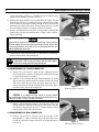
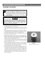
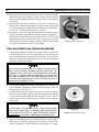
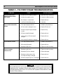
Apeks T20
First St age
Service & Repair Manual
for Authorized Sea Quest Service Centers
©2000 Sea Quest, Inc.
Contents
Introduction .................................................................................................................................................... 3
Safety Precautions .......................................................................................................................................... 3
General Procedures ........................................................................................................................................ 3
Maintenance Schedules ............................................................................................................................ 3
Initial Inspection and Pre-Test ................................................................................................................. 3
Infrequently Used Regulators .................................................................................................................. 4
Work Area & Required Tools ................................................................................................................... 4
O-ring Removal ........................................................................................................................................ 4
Lubrication ............................................................................................................................................... 4
Table 1 – Recommended Tools....................................................................................................................... 5
Table 2 – Lubricant and Cleaner .................................................................................................................. 6
Disassembly Procedures ................................................................................................................................. 7
Disassembly of Yoke Connector .............................................................................................................. 8
Disassembly of DIN Connector ............................................................................................................... 8
Cleaning & Inspection .................................................................................................................................. 10
Reassembly Procedures ................................................................................................................................ 12
Reassembly of Yoke Connector ............................................................................................................. 13
Reassembly of DIN Connector .............................................................................................................. 13
Final Adjustment and Testing Procedures ................................................................................................. 14
Table 3 – Troubleshooting ............................................................................................................................ 16
Repair and Replacement Parts .................................................................................................................... 17
Schematic Drawing ....................................................................................................................................... 18
Apeks Regulator Service and Repair Manual
INTRODUCTION
Apeks regulators are the product of many years of research
and development. Apeks has utilized proven materials
and design to maximize reliability and performance.
This manual is intended only as a guide for the experienced repair person that has completed a Sea Quest/ Apeks
service and repair seminar. It is not intended to educate
inexperienced repair personnel or the consumer in all aspects of Apeks regulator repair. Sea Quest/Apeks repair
seminars are available periodically to Authorized Sea Quest
Dealers. Servicing and repair at the repair shop level
mainly involves cleaning, inspection, adjustment, and replacement of worn parts.
If you have any questions on any of the procedures, inspections, or tests, please contact Sea Quest at:
(877) 253-3483.
SAFETY PRECAUTIONS
This manual provides step by step instructions for the disassembly, inspection, cleaning, reassembly, and testing of
the Apeks T20 first stage regulator. It is recommended
that all steps are followed in the order given. Read each
section completely PRIOR to beginning work described
in that section. This will familiarize the repair technician
with important precautions to take during each service procedure.
Pay close attention to all WARNINGS, CAUTIONS, and
NOTES that are intended to draw your attention to items
of importance.
Definition of Warnings, Cautions, and Notes:
3
GENERAL PROCEDURES
MAINTENANCE SCHEDULES
Regulators are subjected to a variety of environmental elements that over time can affect the performance of the
product. As an Authorized Sea Quest/Apeks Dealer you
are advised to inform your staff and customer that Sea
Quest/Apeks regulator require complete servicing at least
once a year. Under certain circumstances a complete servicing is required every 3-6 months. Some of these circumstances are:
Frequent or improper use
● Inadequate routine freshwater rinsing
● Regulator use in dirty or polluted waters
● Rental use
● Regular use in chlorinated (pool) water
●
Recommended maintenance schedules are based on average use under normal conditions and assume that recommended preventative maintenance and storage procedures
have been followed as outlined in the Sea Quest/Apeks
owner’s manuals.
Advise the customer that any adjustments or servicing on
Sea Quest/Apeks regulators must be performed by Sea
Quest, or by an Authorized Sea Quest/Apeks Dealer that
has attended a Sea Quest authorized service seminar.
INITIAL INSPECTION AND PRE-TEST
Prior to beginning the servicing of the regulator, a preliminary inspection and pre-test of the entire breathing system is recommended. This will help the repair technician
identify any problems that may affect the first stage.
Preliminary inspection should include:
Indicates a procedure or situation that may result in
serious injury or death for either the technician or
the user if instructions are not followed correctly.
Indicates any situation or technique that may result
in potential damage to the product, or render the
product unsafe if instructions are not followed correctly.
NOTE
Is used to emphasize important points and
tips.
● First stage inlet filter - If the first stage inlet filter is
discolored, the entire regulator should be completely serviced. Deposits of rust (red powder) or aluminum oxide
(gray powder) on the filter may indicate that water has
entered the SCUBA cylinder and caused internal cylinder
corrosion. The customer should be notified that their
SCUBA cylinder(s) may be in need of visual inspection,
cleaning and testing. Advise your customers to regularly
inspect the inlet filter for any discoloration or corrosion.
● High pressure (HP) and low pressure (LP) hoses Inspect the hoses carefully for any evidence of cracking,
tearing, or excessive abrasion of the outer rubber covering. Remove all of the hose protectors and examine the
area around the metal fittings for any damage to the hose.
Inspect the fittings for signs of excessive corrosion.
4
All chrome plated parts - Inspect for any excessive corrosion indicating weak or absent chrome plating. Also look
for any signs of peeling or flaking of the chrome plating.
● Regulator pre-test - A regulator pre-test should include
all tests outlined in the test section for each regulator. A
pre-test will assist the technician in determining if there are
any specific performance deficiencies not mentioned by the
customer.
Apeks Regulator Service and Repair Manual
●
Do not use any petroleum based lubricants or products,
or any aerosol sprays to lubricate or clean any part or
component of Apeks regulators. The petroleum base
or propellant gas may attack or weaken the plastic or
rubber parts. Refer to Table 2 for approved lubricants.
INFREQUENTLY USED REGULATORS
Do not assume that the regulator is in good condition because of infrequent use or because it has been in storage.
Deterioration of the O-rings and corrosion can still occur
under these circumstances.
WORK AREA & REQUIRED TOOLS
Servicing and repair of the regulator should be carried out
in a clean well lighted work area. As each regulator is disassembled all parts should be kept separate from parts of
other regulators. Some special tools are required for proper
disassembly and reassembly. Please see Table 1 (page 5)
for a list of these tools.
O-RING REMOVAL
When removing O-rings, care must be taken to not damage
the regulator surfaces in contact with the O-rings. Tools
used to remove O-rings must not have any sharp edges or
points that could scratch metal sealing surfaces. Sea Quest
strongly recommends that all O-ring removal tools should
be made of either brass or plastic.
LUBRICATION
O-rings should be lubricated with an approved compound
(please refer to Table 2 for proper lubricants). O-rings should
be lubricated only with a very light film of grease. Do not
use spray (aerosol) lubricants under any circumstances. The
aerosol propellant may damage the plastic and rubber components of the regulator, and the lubricant will quickly
evaporate, providing little or no lasting benefit.
Apeks regulators are intended for use in water temperatures warmer than 45ºF (7ºC). Colder water may cause
regulators to be more sensitive to a freeflow condition
and can lead to a situation that requires an appropriate
response to prevent serious injury or death. Users of
Sea Quest regulators are advised to ensure that they are
adequately trained to deal with a regulator in a freeflow
condition or an out-of-air emergency before attempting
to dive in a cold water environment.
Apeks Regulator Service and Repair Manual
5
TABLE 1
RECOMMENDED TOOLS
Sea Quest Part No.
Description
Application
N/A
Padded bench vise
Assembly and disassembly of first stage
1003-95
Vise mounting tool
Assembly and disassembly of first stage
AT30
Pin Spanner Wrench
Removal/installation of diaphragm cap
N/A
1/4" wood or plastic dowel
Removal of disc filter
N/A
1/2" wood or plastic dowel
Installation of disc filter
N/A
5mm hex key & hex key socket
Removal/installation of blanking plugs
N/A
6mm hex key & hex key socket
Removal/installation of spring adjuster
N/A
3/4" box wrench torque adapter
Installation of yoke clamp connector
N/A
0-120 inch-lbs torque wrench
Small fittings
N/A
10-50 foot-lbs torque wrench
Large fittings
1116-10
I.P. test gauge
Intermediate pressure testing
9440-22
O-ring tools
O-ring removal & installation
41532
LP air nozzle
Parts drying
N/A
Magnifier w/ illumination
Sealing surface inspection
N/A
Ultrasonic cleaner - 60HZ, 1.3 amp
Brass & stainless steel parts cleaning
Apeks Regulator Service and Repair Manual
6
TABLE 2
LUBRICANT AND CLEANER
Lubricant / Cleaner
Recommended Type
Application
Source
Christo-Lube
MCG-111
All O-rings,
threaded metal parts
as indicated
Lubrication Technologies
310 Morton Street
Jackson, OH 45640
800-477-8704
Chemical Bath Solution
Chromesafe
Chrome-plated brass,
brass, and stainless
steel parts
Sea Quest/ Aqua Lung America
P/N 0201-05
50/50 mix distilled
white vinegar and water
Chrome-plated brass,
brass, and stainless
steel parts
Local grocery stores
General cleaning solution,
degreaser for plastic
and rubber parts,
leak detection
Local grocery stores
Liquid dishwashing detergent Joy®
(diluted with warm water)
DO NOT use muriatic acid for the cleaning of any parts. Muriatic acid, even when strongly diluted, can
harm chrome plating, and may leave a residue that is harmful to O-ring seals and other parts.
Aerosol spray silicone should be avoided because (1) common aerosol propellants may attack plastic
and rubber parts, and (2) because only a slight amount of silicone remains after the solvent evaporates, and provides no lasting benefit.
Silicone rubber requires no lubrication or preservative treatment. DO NOT apply silicone grease or
spray to silicone rubber parts. Doing so will cause a chemical breakdown and premature deterioration of the material.
Apeks Regulator Service and Repair Manual
DISASSEMBLY PROCEDURES
1. Before disassembling the first stage, remove the low pressure second
stage hoses with a b” open-end wrench, and the low pressure inflator hose with a b” or 2" open-end wrench. Remove the high pressure hose with a s” open-end wrench, or the high pressure port plug
with a 5mm hex key. Remove and discard the O-rings from the male
fittings of each hose.
2. Install a vise mounting tool (P/N 1003-95) or a discharged C02 cartridge (P/N 7039-09) connected to a HP port adapter (P/N 1020-85)
into the HP port of the valve body(7) which is located near the serial
number.
DO NOT use a C02 cartridge that has not been discharged. Doing so
may cause the cartridge to rupture, possibly resulting in serious injury.
Figure 1
Removing Spring Adjuster
Figure 2
Removing Diaphragm Cap
3. Secure the vise mounting tool inside a bench vise so that the first
stage is positioned standing vertical outside the vice with the diaphragm cap(2) facing up.
4. Apply a 6mm hex key to the spring adjuster(1) in the center of the
diaphragm cap, and turn the spring adjuster counter-clockwise to
loosen and remove (see Fig. 1). Lift out the spring(3) and examine it
closely with the use of a magnifier to check for any signs of pitting,
rusting, or other corrosion that permeates the surface of the metal.
Set the spring aside if it is found to be in reusable condition, or replace with new as needed.
5. Mate the pin of the spanner tool (P/N AT30) into the bore hole of the
diaphragm cap. While holding the spanner tool securely engaged to
prevent it from slipping, turn the diaphragm cap counter-clockwise to
loosen and remove from the valve body(7), along with the spring carrier(4). (See Fig. 2.)
6. Using a 5mm hex key, install spare blanking plugs(8) into three of the
four LP ports, leaving the primary LP port open while the other ports
are sealed.
7. Direct a short burst of low pressure (50 psi) air through the primary
LP port to partially dislodge the diaphragm(5) from the valve body
(see Fig. 3). Lift out the diaphragm and discard. Remove the blanking plugs that were installed in the previous step.
DO NOT attempt to pry the diaphragm out of the valve body with a
metal instrument. Doing so will permanently damage the seating shoulder, requiring replacement of the valve body.
Figure 3
Removing Diaphragm
8. Remove the valve lifter(6) from the body and set aside. Loosen the
vise to turn the first stage over, and re-secure it so that the HP balance
plug(16) faces straight up.
9. Apply a 6mm hex key to the HP balance plug, and turn it counterclockwise to loosen until it has completely disengaged from the threads
7
Apeks Regulator Service and Repair Manual
8
of the valve body (see Fig. 4). Carefully lift out the balance plug,
along with the spring(12) and HP valve(11).
10. Separate the spring and HP valve from the HP balance plug. Discard
the HP valve, and closely examine the spring with the use of a magnifier to check for any signs of pitting, rusting, or other corrosion that
permeates the surface of the metal. Set the spring aside if it is found
to be in reusable condition, or replace with new as needed.
11. Remove and discard both of the static O-rings(14&15) from the HP
balance plug, and also the small dynamic O-ring(13) that is held inside the opening.
Figure 4
Removing HP Balance Plug
Use only a brass or plastic O-ring tool when removing O-rings from the
HP balance plug. Use of a sharp steel instrument can easily scratch the
O-ring sealing surface, which will result in a permanent leak that will
require replacement of the part.
12. Reposition the valve body inside the vice and secure it with the connector (Yoke or DIN) facing straight up.
Before proceeding, determine whether the first stage is con-
NOTE figured with a DIN or yoke connection, and refer to the appropriate disassembly procedure provided below.
13. DISASSEMBLY OF YOKE CONNECTOR
A. Remove the yoke screw(37) from the yoke clamp(34) and remove the protective cap(35). Examine the condition of the spare
O-ring(36) and replace as needed.
B. Apply a w" box wrench to the yoke clamp connector(32). Using
firm, steady force, turn the connector counter-clockwise to loosen
and remove from the valve body and yoke clamp (see Fig. 5).
Lift the connector and clamp straight off the valve body. Separate these items, and set the clamp aside.
Figure 5
Removing Yoke Connector
CAUTION: It is important that the wrench is securely seated
over the entire hex surface of the yoke clamp connector to prevent any
damage to the part. Do not use impact to loosen.
C. Remove and discard the O-ring(33) from the base of the yoke
clamp connector. Stand the connector on a flat surface with the
disc filter(31) facing down. Insert a 4" wooden or plastic dowel,
and tap out the filter with a small mallet.
14. DISASSEMBLY OF DIN CONNECTOR
A. Remove the protective cap(30) from the threads of the
handwheel(27). Apply a 6mm hex key to the hand wheel connector(28), and turn it counter-clockwise to loosen and remove
(see Fig. 6).
Figure 6
Removing DIN Connector
Apeks Regulator Service and Repair Manual
9
B. Remove both O-rings(25&29) and the conical filter(26) from the
handwheel connector. Discard these items and do not reuse.
Closely inspect the condition of the handwheel connector, including the thread and the sealing areas of both O-rings. Replace the
part if any damage is found, or set it aside to be reused.
C. Closely inspect the threads of the handwheel to ensure they are
free of any burrs or other damage that could prevent proper threading. Replace the part if damage is found, or set it aside to be
reused.
15. Loosen the vice to remove the valve body, and remove the vise mounting tool. Remove all remaining blanking plugs, and remove and discard their O-rings.
16. Under adequate lighting and magnification, closely inspect the condition of the sealing crown inside the valve body to check for any
scratches, corrosion, or other signs of damage.
NOTE: If the sealing crown of the valve body appears to be
NOTE damaged and a persistent intermediate pressure leak was detected prior to disassembly, it may be necessary to replace the
valve body with new.
This concludes the disassembly procedures.
Apeks Regulator Service and Repair Manual
10
CLEANING & INSPECTION
1. All parts should be cleaned first in a warm (not over 120°F) mild soap
and water solution. Use a soft nylon bristle brush to help remove any
excess or loose contamination. After an initial warm water and soap
cleaning all parts should be thoroughly rinsed in clean fresh water
and dried with filtered low pressure (30 psig) air. After an initial
cleaning in warm soap and water solution, metal parts should be
cleaned in an ultrasonic cleaner using the appropriate ultrasonic cleaning solution (see Lubricant and Cleaner Table 2).
Be sure all O-rings and other rubber or plastic parts are re-
NOTE moved before cleaning in an ultrasonic cleaner or chemical bath.
Cleaning solutions may damage these components.
2. If an ultrasonic cleaner is not available, metal parts can be cleaned by
soaking the metal parts in a chemical bath solution of Chromesafe
(see Lubricant and Cleaner Table 2) and agitating gently for 3-4 minutes. Cleaning of metal parts can also be done by soaking in a mild
acetic solution (distilled white household vinegar) for 10-15 minutes.
Cleaning times in excess of those recommended may damage
NOTE plated parts. Never clean parts for longer than specified by the
manufacturer of the solution used. After completion of cleaning in any solution, thoroughly rinse parts with clean fresh water
and blow dry with low pressure (30 psig) air. Only brass, plated
brass, and stainless steel parts should be immersed in chemical cleaning solutions.
Use hand and eye protection when handling chemical cleaning solutions.
3. After cleaning, all parts should be thoroughly rinsed in fresh water
and dried with filtered low pressure (30 psig) air.
Before performing any reassembly, it is important to inspect all
NOTE parts, both new and those that are being reused, to ensure that
each part is clean and free of any contamination, corrosion, or
blemish.
4. All O-rings should be replaced at every servicing. New O-rings should
be inspected for contamination and/or imperfections, and lightly
dressed with a thin film of approved lubricant prior to installation.
(See Lubricant and Cleaner Table 2.)
Do not use any petroleum based lubricants or products, or any aerosol
silicone sprays on any part of Sea Quest regulators. The petroleum
base or propellant gas may attack or weaken plastic or rubber parts.
Refer to Table 2 for a list of approved lubricants.
Apeks Regulator Service and Repair Manual
11
5. In addition to the O-rings, the following parts should be routinely
replaced at the time of servicing:
● Diaphragm (5)
● HP Valve Seat (11)
● Disc Filter - Yoke Clamp Connector (31)
● Conical Filter - DIN Connector (26)
All O-rings and the above mentioned routine replacement parts are
included in the Overhaul Service Kit (P/N APO227).
6. The following parts should be closely inspected for the damage listed
below. Close inspection is best accomplished by using strong magnification under bright lighting.
● Valve Body (7) Inspect all cavities for any nicks, scratches, pitting,
or any defects in the plating. Pay particular attention to the sealing
edge of the valve cone and the diaphragm seating shoulder.
● Springs (3&12) Inspect for signs of permanent corrosion, including
pitting or cracks in the surface of the metal.
● HP Balance Plug (16) Inspect the interior cavity for any nicks,
scratches, pitting, or any defects in the plating.
● DIN or Yoke Connector (28 or 32) Examine the condition of the
threads and the O-ring sealing groove at the base for any signs of
damage.
● DIN Handwheel (27) Examine the condition of the threads for any
signs of damage.
7. If any of the listed parts show any damage, they must be replaced
with new.
8. Check all metal parts for excessive wear or corrosion. Check all metal
sealing surfaces which make contact with O-rings for any signs of
contamination and/or imperfections that may cause leakage past the
O-ring seal. Examine all chrome plated surfaces for any evidence of
peeling or flaking of the chrome plating. Inspect all threads for galling, cross threading, or damage to the chrome plating. If any parts
show damage or excessive wear, they must be replaced with new.
Apeks Regulator Service and Repair Manual
12
REASSEMBLY PROCEDURES
Before performing any reassembly, it is important to inspect all
NOTE parts, both new and those that are being reused, to ensure that
every part and component is perfectly clean and free of any
dust, corrosion, or blemishes. Before dressing each O-ring
with Christo-Lube®, check to ensure it is clean, supple, and
free of any blemish.
Use only genuine Apeks parts, subassemblies, and components whenever assembling any Apeks product. DO NOT attempt to substitute an
Apeks part with another manufacturer’s, regardless of any similarity in
shape, size, or appearance. Doing so may render the product unsafe,
and could result in serious injury or death.
1. Insert the stem of the valve lifter(6) into the center bore hole inside
the low pressure side of the valve body(7).
2. Lay the diaphragm(5) over the valve lifter inside the valve body, and
gently tamp it down below the threads until it is seated evenly on all
sides.
3. Place the spring carrier(4) in the center of the diaphragm. Mate the
larger diameter threads of the diaphragm cap (6) onto the valve body,
and tighten the diaphragm cap clockwise by hand until snug.
4. Place the spring(3) inside the center of the diaphragm cap so that it
rests directly over the spring carrier.
5. Mate the spring adjuster(1) into the center of the diaphragm cap ,
directly over the spring. Apply a 6mm hex key to turn the spring
adjuster clockwise to its correct preliminary setting until it is set flush
with the top of the diaphragm cap (see Fig. 7).
6. Turn the first stage over and carefully lower the sealing end of the HP
valve(11) straight down over the pin of the valve lifter, inside the high
pressure side of the valve body.
7. Install the small dynamic O-ring(13) into the recess inside the small
end of the HP balance plug, and tamp it down with a non-metallic
instrument to ensure it is seated evenly on all sides. Next, install the
static O-rings(14&15) onto their respective grooves.
8. Fit the spring(12) over the small end of the HP balance plug. Then,
carefully mate the balance plug with spring straight down into the
valve body, over the stem of the HP valve. Press down with the palm
of one hand to compress the spring over the HP valve. While maintaining downward pressure, turn the balance plug clockwise to engage the threads of the valve body, and then continue turning by hand
until it is lightly snug.
Figure 7
Adjustment Screw Pre-setting
Apeks Regulator Service and Repair Manual
13
9. REASSEMBLY OF YOKE CONNECTOR
A. Lay a new disc filter(31) inside the yoke clamp connector(32),
and press it firmly into place with the use of a wooden or plastic
dowel, so that it is seated evenly on all sides.
B. Install the O-ring(33) into the recess at the base of the yoke clamp
connector.
C. Insert the yoke clamp connector through the bottom of the yoke
clamp(34), and place the distance piece(10) over the end of the
connector, with the flat surface held flush against the flat bottom
of the yoke clamp (see Fig. 8).
D. While holding the yoke clamp, connector, and distance piece together so that the curvature of the distance piece fits against the
valve body, mate the connector into the valve body and turn it
clockwise by hand until snug.
E. Install a new spare O-ring(36) onto the protective cap(35), and fit
the loop end onto the groove at the top of the yoke clamp. Install
the yoke clamp screw(37) into the yoke clamp, but do not seal the
protective cap at this time.
10. REASSEMBLY OF DIN CONNECTOR
Figure 8
Installing Yoke Clamp Assembly
Figure 9
Installing DIN Connector Assembly
A. Install both O-rings(25&29) onto the handwheel connector(28).
B. Insert the small end of the conical filter(26) through the small Oring and into the threaded end of the handwheel connector, being
careful to avoid pressing the filter too far past the O-ring, which
will cause it to become unseated.
C. Mate the handwheel connector through the threaded end of the
handwheel(27), and place the distance piece(10) over the end of
the connector, with the flat surface held flush against the flat bottom of the handwheel (see Fig. 9).
D. While holding the handwheel, connector, and distance piece together so that the curvature of the distance piece fits against the
valve body, mate the connector into the valve body and turn it
clockwise by hand until snug.
11. Install a vise mounting tool (P/N 1003-95) or a discharged C02 cartridge (P/N 7039-09) connected to a HP port adapter (P/N 1020-85)
into the HP port of the valve body(7) which is located near the serial
number.
DO NOT use a C02 cartridge that has not been discharged. Doing so
may cause the cartridge to rupture, possibly resulting in serious injury.
Figure 10
Tightening Diaphragm Cap
12. Secure the vise mounting tool inside a bench vise so that the first
stage is positioned standing vertical outside the vice with the diaphragm cap facing up.
13. Mate the pin of the spanner tool into the bore hole of the diaphragm
cap . While holding the spanner tool securely engaged to prevent it
from slipping, turn the diaphragm cap clockwise to tighten until it is
completely snug and flush (metal against metal) with the valve body
(see Fig. 10).
Apeks Regulator Service and Repair Manual
14
14. Loosen the vise to turn the first stage over, and re-secure it so that the
HP balance plug faces straight up. Apply a torque wrench with 6mm
hex key socket to tighten the balance plug to a torque measurement of
12 foot-lbs.
15. Reposition the first stage inside the vice and secure it with the connector (Yoke or DIN) facing straight up. Apply a torque wrench with
a w" box wrench torque adapter (Yoke) or 6mm hex key socket (DIN).
(see Fig. 11.) Tighten the connector to 12 foot-lbs.
16. Loosen the vice to remove the first stage, and remove the vise mounting tool. Install all O-rings(9&18) onto all hoses and port plugs(8&17).
Install all LP and HP hoses and port plugs into the valve body, and
tighten the port plugs clockwise until snug. Apply a torque wrench
with respective crow foot to tighten each hose at the first stage fitting
to a torque measurement of 40 (±5) inch-pounds.
Figure 11
Torqueing Yoke Connector
FINAL ADJUSTMENT AND TESTING PROCEDURES
1. Connect the intermediate pressure test gauge either to a quick-disconnect inflator hose, or to the female fitting of a second stage LP
hose, depending on the connection of the test gauge. Check to ensure
there are no open ports and that all hoses are securely connected at
both ends, with no open fittings.
Before testing intermediate pressure, it is important to connect the first
stage to a fully assembled and properly adjusted second stage. This
will provide a safety relief valve if the intermediate pressure exceeds
155-170 psi. If a properly adjusted second stage is not available, be
sure to open the bleed valve of the test gauge before pressurizing. Failure to relieve intermediate pressure in excess of 400 psi may result in
damage to the test gauge or LP hose.
2. Check to ensure that the first stage spring adjuster(1) is correctly set
to its preliminary adjustment; exactly flush with the top of the diaphragm cap(2). (See Fig. 12.)
3. Connect the first stage to a filtered air source of 500 psi, and slowly
pressurize the first stage. While closely monitoring the IP test gauge
to ensure that the intermediate pressure does not rise above 120 psi,
slowly turn the knob of the bleed valve clockwise until it is completely shut.
If a second stage is not connected to the first stage and the intermediate pressure rises above 200 psi, immediately reopen the bleed valve of
the test gauge and shut off the air supply. Refer directly to Table 3 Troubleshooting, and remedy as needed before proceeding further.
4. When the intermediate pressure has stabilized below 120 psi, apply a
6mm hex key to turn the spring adjuster clockwise in small increments of adjustment. While turning the spring adjuster, it is impor-
Figure 12
Adjustment Screw Pre-setting
Apeks Regulator Service and Repair Manual
15
tant to simultaneously purge the second stage or briefly turn the test
gauge bleed valve open and shut. Monitor the test gauge while adjusting in this manner until the intermediate pressure locks up between 115-120 psi.
Failure to cycle the regulator during adjustment can result in a false
reading of the intermediate-pressure.
5. When the intermediate pressure has been determined to be stable at
120 psi or less, increase the inlet pressure to between 2,500 – 3,000
psi while checking the IP test gauge once again to ensure that the
intermediate pressure does not rise above 135 psi. If the intermediate
pressure rises above 135 psi, immediately purge the second stage, or
re-open the bleed valve of the test gauge, and shut off the air supply.
Refer directly to Table 3 - Troubleshooting, and remedy as needed.
6. Repeat the adjustment procedure in step 4 to adjust the first stage
intermediate pressure to exactly 135 psi. Repeatedly purge the second stage or open and shut the test gauge bleed valve at least 15 times
to ensure that the intermediate pressure locks up consistently and remains stable at 135 (±5) psi, with no signs of creeping or fluctuation.
7. After performing the overhaul and adjustment procedures outlined in
the Apeks Second Stage Service & Repair Manual, connect the first
and second stage regulators to perform the following tests:
8. External Leak Test – Connect the regulator to a cylinder which contains 2,500 - 3,000 psi, and open the cylinder valve to pressurize the
system. Submerge the cylinder and regulator in a test tank of fresh
water, and observe closely for up to one minute to check for the formation of bubbles. If a steady stream of bubbles is present, the system must be disassembled at the source to check sealing surfaces,
assembly sequence, and component positioning in order to correct
the problem(s).
Before disassembling to correct any leaks, rinse the entire regu-
NOTE lator thoroughly with fresh water and blow out all residual moisture with filtered, low-pressure (30 psi) air. Disassemble and
remedy the problem, referring to Table 3 – Troubleshooting.
9. Subjective Breathing Test – Depress the second stage purge to ensure
that the volume of airflow is adequate to clear the second stage. Then,
breathe deeply from the mouthpiece. A properly serviced and adjusted regulator should deliver a smooth, uninterrupted airflow upon
deep inhalation; without excessive effort, hesitation, or freeflow. If
any problems occur, refer to Table 3 – Troubleshooting.
This concludes the annual service procedures for
The Apeks T20 First Stage Regulator.
Figure 14
Tightening Environmental End Cap
Apeks Regulator Service and Repair Manual
16
TABLE 3 – T20 FIRST STAGE TROUBLESHOOTING
SYMPTOM
Restricted airflow/ high inhalation resistance through
entire system.
High or unstable intermediate
pressure
Low intermediate pressure
External air leakage
(Immersion Test)
CAUSE
ACTION REQUIRED
1. Cylinder valve not completely opened.
1. Open valve, check fill pressure.
2. Cylinder valve requires service.
2. Connect to a different cylinder.
3. Disc filter(31) is contaminated.
3. Replace with new.
4. Insufficient intermediate pressure.
4. See below.
1. First-stage improperly adjusted.
1. Readjust spring adjuster(1).
2. HP valve seat(11) damaged or worn.
2. Replace HP valve seat.
3. HP balance plug O-ring(16) damaged
or worn.
3. Replace O-ring.
4. HP balance plug(16) damaged.
4. Replace with new.
5. Sealing surface of HP valve body(7)
damaged.
5. Replace with new.
6. Valve spring(12) weakened or damaged.
6. Replace with new.
1. First-stage improperly adjusted.
1. Readjust spring adjuster(1).
2. Main spring(3) damaged.
2. Replace with new.
3. Diaphragm cap(2) loose.
3. Tighten flush with valve body.
1. Diaphragm cap(2) loose.
1. Tighten flush with valve body.
2. Diaphragm(5) worn or damaged.
2. Replace diaphragm.
3. Diaphragm seating surface inside
first stage valve body(7) damaged.
3. Replace with new.
4. HP balance plug O-ring(14 or 15) damaged. 4. Replace with new.
Recommended treatments which require disassembly of the regulator must be performed during
a complete overhaul, according to the prescribed procedures for scheduled, annual service. Do
not attempt to perform partial service. For assistance with a problem not described here, contact
a Sea Quest Technical Advisor.
Apeks Regulator Service and Repair Manual
17
REGULATOR REPAIR AND REPLACEMENT PARTS
APEKS T20 FIRST STAGE
Item
Description
Part #
Item
Description
Part #
1
Spring Adjuster
AP1474
21
Hydrostatic Transmitter
AP1483
2
Diaphragm Cap
AP1485
22
1st Stage Decal
AP1477
3
Spring
AP1475
23
Hydrostatic Diaphragm
AP1482
4
Spring Carrier
AP1476
24
Environmental Cap
AP1484
5
Diaphragm
AP1478
25
O-ring
AP1409
6
Valve Lifter
AP1479
26
Conical Filter
AP1472
7
Valve Body (US1 & DS1)
AP5200
27
Handwheel
AP1470
Valve Body (DS1 & DS4)
AP5201
28
Connector
AP1471
8
7/16" Blanking Plug
AP1413
29
O-ring
AP1166
9
O-ring
AP1445
30
Protective Cap
AP1264
10
Distance Piece
AP1446
31
Disc Filter
AP1406
11
HP Valve
AP1419
32
Yoke Clamp Connector
AP1407
12
Spring
AP1415
33
O-ring
AP1409
13
O-ring
AP1299
34
Yoke Clamp
AP1403
14
O-ring
AP1410
35
Protective Cap
AP1404
15
O-ring
AP1300
36
O-ring
AP1166
16
HP Balance Plug
AP5202
37
Yoke Clamp Screw
AP1400
17
Blanking Plugs (US4 & DS4)
AP1408
38
Decal
AP5015
18
O-rings (US4 & DS4)
AP1409
19
Diaphragm Clamp
AP1473
n/s
Overhaul Service Kit (Yoke)
APO227
20
Spring Adjuster
AP1474
n/s
Overhaul Service Kit (DIN)
NOTE: Items in bold are included in the Overhaul Service Kit
APO227/1
Apeks Regulator Service and Repair Manual
18
Apeks T20 First Stage
Schematic Drawing
38
31
37
30
36
32
35
29
33
28
34
16
14
10
27
13
12
11
26
7
25
6
3
4
5
2
1
18
9
8
17
15